 ParedesParedes
Os produtos da Vectorworks Design Series possuem uma variedade de ferramentas e comandos para projetar paredes retas e curvas. Desenhe paredes usando a ferramenta Parede e a ferramenta Parede Curva ou crie-as automaticamente a partir de objetos existentes no desenho, incluindo espaços, polígonos e formas. As ferramentas também incluem a capacidade de criar paredes cortina. Métodos para criar paredes incluem:
• Ferramenta Parede e Ferramenta Parede Curva
• Criar Paredes de Polígonos
• Criar Paredes de Espaços
• Criar Polígonos a partir de Paredes
~~~~~~~~~~~~~~~~~~~~~~~~~
 Criando Paredes
A ferramenta Parede encontra-se no conjunto de ferramentas Parede (Fundamentals) e no conjunto de ferramentas Parede/AEC (Design Series).
Use as ferramentas de parede para desenhar paredes retas ou curvas, ou se você estiver usando o Vectorworks Architect ou Landmark, paredes cortina, e para juntar estas paredes a outras paredes. Cada segmento de parede é tratado como se fosse um objeto separado. Você pode juntar as paredes automaticamente ao desenhá-las, ou juntá-las após o desenho usando uma das opções de junção. Outros recursos de parede incluem adicionar traços dos componentes e preenchimentos a paredes, adicionar fechamentos e guarnições, e inserir símbolos (como portas e janelas) a elas. Você também pode adicionar e remover os picos em uma parede, se a elevação mudar de uma ponta à outra da parede.
Parâmetros adicionais de paredes estão disponíveis somente no Architect e no Landmark. Estes produtos oferecem o recurso de criar, salvar e usar estilos de paredes e de criar novas classes de paredes ou de componentes durante a criação e edição de paredes. No Vectorworks Architect, as paredes e os seus componentes também oferecem o recurso de definir os limites de topo e base de acordo com os níveis do andar atual, ou os níveis do andar acima ou abaixo do andar atual da parede. Além disso, a informação relativa à energia especifica para paredes é considerado quando há uma análise de energia.
Existem quatro formas de se posicionar paredes em relação à linha de controle. A linha de controle pode ser definida em relação à parede ou a um componente de núcleo opcional. Paredes retas podem ser desenhadas no modo Polígono ou Retângulo. Estes modos são ativados pelos botões na barra de ferramentas.

Modo |
Descrição |
|---|---|
Alinhamento pela Esquerda |
As paredes serão desenhadas ao longo de sua face esquerda (no sentido de criação) |
Modo de Alinhamento Central |
As paredes serão desenhadas pela sua linha de eixo |
Alinhamento pela Direita |
As paredes serão desenhadas ao longo de sua face direita (no sentido de criação) |
Modo de Alinhamento Personalizado |
Neste caso as paredes serão desenhadas a partir de uma distância personalizada (Dist. Controle); muito útil quando desenhar paredes com Cavidadess |
Linha de Controle da Parede |
Permite definir a linha de controle em relação a parede |
Linha de Controle do Componente Núcleo |
Permite definir a linha de controle em relação ao componente da parede definido como o componente de núcleo nas preferências da parede |
Polígono |
Desenha um sistema de parede ou parede reta, clicando em cada canto para criar uma forma personalizada, semelhante à ferramenta Polígono |
Retângulo |
Desenha um sistema de parede retangular com dois cliques, semelhante ao canto da ferramenta Retângulo para o modo de Canto a Canto |
Controle de Criação de Arcos de Paredes Curva |
Selecione o método de criação do arco para usar quando estiver desenhando paredes arredondadas; para mais informações dos modos de criação dos arcos, veja Creating Arcs |
Preferências das Paredes |
Define os parâmetros físicos da parede |
Estilo de Parede |
Os arquivos e pastas disponíveis no documento atual, em outros documentos abertos, e nas bibliotecas são listadas na esquerda. Selecione um arquivo para exibir miniaturas dos estilos de parede disponíveis naquele local, e selecione o estilo desejado. |
Veja Direção da Parede para mais informações sobre como o ponto inicial e a direção de desenho da parede afetam os lados interno e externo da parede.
Os pontos de alinhamento mestre não podem ser usados com as ferramentas Parede ou Parede Redonda.
~~~~~~~~~~~~~~~~~~~~~~~~~
 Desenhando Paredes Retas
Ferramenta |
Workspace: Conjunto de Ferramentas |
|---|---|
Parede
|
• Architect e Spotlight: Building Shell • Landmark: Building Shell and Site Planning |
A ferramenta Parede cria um objeto híbrido representativo de uma parede, que possui simultaneamente tanto a parte 2D quanto a 3D do elemento. Paredes podem ser desenhadas tanto na vista Topo/Panta quanto na vista 3D.

Crie parades desenhando-as com o mouse, ou com o mouse e a Barra de Dados (veja Usando a Barra de Dados). O procedimento a seguir assume que as paredes sejam desenhadas com o mouse.
Se as paredes forem desenhadas usando a barra Dados, a configuração do modo Linha de controle determinará se as dimensões inseridas são para a extremidade esquerda, central ou direita da parede ou um local personalizado.
Para criar uma parede reta:
1 Clique na ferramenta e, em seguida, clique no modo de linha de controle desejado e no modo Polígono ou Retângulo, veja( Criando Paredes).
2 Faça um dos seguintes:
• Para usar um estilo de parede existente nas bibliotecas de recursos, clique em Estilo de parede na barra de ferramentas. No Administrador de Recursos, clique duas vezes em um recurso para ativá-lo. Ou, para desenhar uma parede não estilizada, deixe a configuração <Unstyled> como está. Prossiga para o passo 4.
• Clique em Preferências. Na caixa de diálogo Preferências de parede, defina as propriedades padrão. As propriedades podem ser editadas na paleta Informações do Objeto.
► Clique para exibir/ocultar parâmetros.
3 Clique Editar Atributos de Parede para especificar os atributos da parede.
A janela de diálogo de Atributos de Parede irá abrir. Os atributos de uma parede sem estilo é inicialmente um conjunto de parâmetros mostrados pela The Attributes Palette. Caso eles sejam modificados aqui, a Paleta de atributos irá refletir as mudanças nos atributos da parede selecionada (após sair da janela de Preferências de Parede).
Preenchimento, traço e opacidade podem ser definidos através da classe associada à parede ao invés de usar os atributos da janela de Atributos de Parede. Caso a classe da parede seja alterada mais tarde, a parede irá alterar automaticamente para refletir os atributos da nova classe. Os atributos da parede não podem ser sobrepostos de uma forma individual (por exemplar); caso o estilo de uma parede use os atributos da classe, todas as paredes com este estilo terão que usar os atributos da classe. No entanto, paredes com o mesmo estilo podem ser posicionadas em diferentes classes.
► Clique para exibir/ocultar parâmetros.
4 Clique OK para retornar para a janela de Preferências de Parede. Caso deseje adicionar componentes internos a sua parede, clique no botão Novo Componente para definir cada componente (veja Creating Wall Components). A Espessura Total será definida pela espessura dos componetes de parede.
Nos produtos Vectorworks Architect e Landmark, componentes da parede pode ser atribuído a uma classe; isso permite máxima flexibilidade uma vez que as classes de componentes podem ser mostrados ou escondidos em separado a partir da classe parede. Para controlar a aparência e visibilidade, selecione uma classe a partir da lista de classes presentes no projeto ou criar uma nova classe. Selecione <Object Class> para colocar os atributos do componente na mesma classe como o objeto parede. Por padrão, os componentes são atribuídos à classe de parede.
Quando um componente está em uma classe invisível, o seu preenchimento e linhas estarão ocultas. Componentes invisível no interior e exterior de uma parede provocam ajustes no preenchimento e nas linhas da parede apenas nos componentes visíveis, fazendo parecer que a parede está mais fina do que a sua largura real. Isso permite que as paredes possam mostrar apenas os seus componentes estruturais, por exemplo. Se todos os componentes estão invisíveis, a parede exibe em sua espessura total, sem componentes.

A preferência Ocultar Detalhes podem ser usados para esconder componentes da parede baseado em escala (requer Vectorworks Design Series); veja Hiding Wall Components.
5 Clique na guia Opções de Inserção para definir as opções de inserção de parede.
Paredes de cortina tem poucos parâmetros diferentes; veja Criando Paredes Cortina.
► Clique para exibir/ocultar parâmetros.
6. Clique na tab Texturas para seleciona quais texturas serão aplciadas nas diferentes partes da parede (requer Renderworks).
Texturas das paredes cortina são controladas pelos ajustes dos perfis e dos painéis na aba Definição; veja Criando Paredes Cortina.
► Clique para exibir/ocultar parâmetros.
7 Clique na aba Dados (Vectorworks Architect/Landmark requeridos) para especificar informações do registro da parede, o qual é IFC-compliant e possa ser incluído em um cronograma de paredes. Estes campos são opcionais; entre informações somente onde precisar.
8 Quandos os parâmetros da parede estiverem especificados, e muitas mudanças tiverem sido salvas em um recurso de estilo de parede se desejado (Vectorworks Design Series requirido), clique OK.
Nas versões Design Series, um estilo de parede é salvo como um recurso no arquivo, e este aparecerá tanto no Administrador de Recursos como na lista de Estilos de Paredes na Barra de Ferramentas. Veja Criando Estilos de Parede.
9. Se o modo Poligonal estiver selecionado, clique no ponto inicial do primeiro segmento da parede.
10. Clique para finalizar o primeiro segmento de parede.
Para continuar a criação de parede, clique no final de cada segmento de parede adicional.
11. Duplo-clique para finalizar a parede se o ponto inicial e final não estiverem na mesma localização; caso contrário, clique no ponto inicial (uma dica do SmartCursor será mostrada) para finalizar a parede.
Alternativamente, após completar tudo menos o clique final, pressiona a tecla de atalho "K" para fechar automaticamente a sequencia de segmentos de paredes. Veja Modifying Special Shortcuts para alterar o atalho.

Quando desenhar uma rede de paredes regulares, como um retangulo, mova o mouse na direção próxima ao ultimo clique e aperte o atalho de teclado antes de clicar; o programa irá extrapolar o alinhamento correto e posição do ultimo clique, e completar a rede de paredes.

12. Se modo Retangulo estiver selecionado, clique no ponto inicial da parede; esse ponto se tornará o canto do sistema retangular de paredes. Mova o mouse para o canto oposto até que o tamanho desejado seja exibido.
13. Clique para definir o ponto de canto do sistema de paredes. Quatro paredes serão criadas.
Quando a preferencia do Vectorworks Unção Automática de Paredes estiver ativada, paredes desenhadas em modo retangulo que sobrepõem ou tocam alguma outra, interagem. Dessa forma sistemas complexos de paredes poderão ser desenhados de forma rápida. Veja Automatically Joining Walls in Rectangle Mode para as regras que definem essas interações.

As propriedades de parede podem ser editadas na paleta de Informações de Objeto.; veja Propriedades da Parede.
~~~~~~~~~~~~~~~~~~~~~~~~~
 Desenhando Paredes Curvas
Ferramenta |
Workspace: Conjunto de Ferramentas |
|---|---|
Parede Curva
|
• Architect e Spotlight: Building Shell • Landmark: Building Shell and Site Planning |
Paredes curvas, híbridas podem ser criadas e juntadas às paredes retas. A ferramenta Parede Curva é essencialmente a combinação das funções da ferramenta Parede e da ferramenta Arcos. Ela vai criar uma parede semicircular com as mesmas características e elementos das paredes retas. Paredes podem ser desenhadas tanto na vista Topo/Planta como na vista 3D.

Para desenhar paredes curvas:
1 Clique na ferramenta, e, em seguida, clique no modo de linha de controle desejado (veja Criando Paredes) e modo de criação de arco (veja Creating Arcs).
2 Clique em Preferências e insira os parâmetros conforme descrito em Desenhando Paredes Retas.
3 Clique para começar a desenhar a parede.
4 Clique para terminar a parede.

|
Clique aqui para uma dica em vídeo sobre este tópico (requer acesso à internet). |
~~~~~~~~~~~~~~~~~~~~~~~~~
 Direção da Parede
O ponto inicial e direção da parede desenhada determinam os lados da parede. O centro da parede é sempre o mesmo, mas o lado esquerdo e direito dependem da direção do desenho. Por exemplo, quando desenhar uma parede em sentido horário, o lado esquerdo é sempre o lado externo; em uma direção anti-horário, ele se torna o interno.
Desenhar paredes no sentido horário é sempre recomendável. Os estilos de parede disponíveis nas bibliotecas do Vectorworks esperam que o exterior da parede esteja no lado esquerdo.

Novas paredes desenhadas com o modo Retângulo são desenhadas no sentido horário, independentemente do posicionamento do clique. (Veja Automatically Joining Walls in Rectangle Mode para uma descrição da direção da parede quando a opção Subtrair é usada.)
A direção da parede pode ser revertida clicando em Inverter Lados, na paleta Info de Objetos.
 Usando
Estilos de Parede
Usando
Estilos de ParedeO uso opcional de estilos de parede facilita o desenho de paredes ao salvar as configurações de preferências de parede para que possam ser facilmente selecionadas como o estilo padrão ao desenhar novas paredes, ou para que elas possam ser aplicadas a paredes existentes. Estilos de parede são recursos que podem ser importados para outros arquivos e compartilhados como padrões de escritório.
Um estilo de parede contém uma quantidade significativa de informações:
• Composição e estrutura da parede (componentes para paredes padrão e quadros e painéis para paredes cortina)
• Opções de inserção (restrições de altura, fechamentos, classificação e valores de análise energética (Vectorworks Architect necessário))
• Atributos de parede (preenchimento, traço, espessura da linha, classificação, recursos de textura, recursos de hachura)
• Restrições de parede vertical (por elevação de camada, altura de parede de camada ou, para o programa Vectorworks Architect, níveis de camada de andar)
• Restrições de componentes, para paredes padrão
• Outros dados não-geométricos (nome do estilo de parede, dados térmicos, dados do produto e assim por diante)
Como um estilo de parede contém muita informação, pode ser demorado criar um a partir do zero. No entanto, uma variedade de estilos de parede é fornecida nas bibliotecas. Um estilo de parede selecionado é automaticamente importado para o arquivo atual e exibido no Administrador de Recursos.
Dependendo de como você usa estilos de parede e qual produto está em uso, geralmente é necessário apenas um tipo de estilo de parede, simples ou restrito. Estilos de parede fornecidos pela ferramenta Parede ou Parede Curva em um arquivo em branco são estilos de parede simples que usam o método convencional de determinar a altura da parede superior e inferior de acordo com a elevação da camada ou a altura da parede da camada. No entanto, os estilos de parede restrita são fornecidos em modelos nomeados com um prefixo BIM; estes estão disponíveis para os usuários do Vectorworks Architect na lista Usar Modelo de Documento na janela de diálogo Criar Documento. Esses estilos de parede são restritos às configurações do nível de andar nesses modelos, e fornecem detalhes adicionais da parede, precisão e flexibilidade. Mais informações sobre o uso de estilos de parede e níveis de andar com BIM estão disponíveis no site do Vectorworks.
Para converter uma parede selecionada em uma parede sem estilo, selecione Converter para Parede Sem Estilo na lista Estilo da Paleta Info de Objetos. Quando uma parede se torna sem estilo, ela perde todos os seus dados não geométricos.
As opções de inserção de uma parede com estilo (incluindo alturas de paredes e componentes, restrições, classe e fechamentos) são propriedades que podem ser alteradas a partir da Paleta Info de Objeto sem exigir uma nova definição de estilo.
Selecione Ferramentas > Relatórios > Criar Relatório para adicionar uma planilha Relatório de Área de Parede e/ou Estilo de Parede ao desenho. Alternativamente, no Administrador de Recursos, selecionar Vectorworks Libraries\Defaults\Reports_Schedules\Architectural Reports.vwx. Arraste a planilha Relatório de Area de Parede e/ou Estilo de Parede para o desenho. A planilha é preenchida com informações dos objetos no desenho atual.
Um recurso de estilo de parede pode ser exportado para outro arquivo do Vectorworks; veja Exporting Resources. Para disponibilizar um estilo de parede personalizado como conteúdo padrão das janelas de diálogo, colocar o arquivo que contém o estilo de parede na pasta de conteúdo padrão apropriada. Veja Creating Custom Default Content para detalhes
Estilos de parede não utilizados podem ser removidos; veja Purging Items from a File.
~~~~~~~~~~~~~~~~~~~~~~~~~
 Criando
Estilos de Parede
Criando
Estilos de ParedeFerramenta |
Espaço de trabalho: Conjunto de Ferramentas |
|---|---|
Parede
|
• Architect e Spotlight: Paredes / AEC • Landmark: Paredes / AEC e Plantas do Terreno |
Para criar um estilo de parede:
1 Clicar na ferramenta e, em seguida, clicar em Preferências.
A janela de diálogo Preferências da Parede abrirá.
2 Para modificar um estilo de parede existente, selecionar o estilo de parede de uma biblioteca ou o arquivo atual. Alternativamente, selecionar Sem Estilo como o estilo de parede e definir os parâmetros.
3 Especificar os parâmetros da parede e componentes conforme descrito em Desenhando Paredes Retas.
4 Clicar em Salvar Preferências como Estilo de Parede.
A janela de diálogo Atribuir Nome abrirá.
5 Digitar um nome exclusivo para o estilo de parede.
Se o nome do estilo de parede já existir, será solicitado que você cancele e selecione um nome diferente ou substitua o estilo de parede existente pelo estilo de parede editado, para todas as paredes que usam esse estilo. Se você estiver substituindo estilos de parede, a janela de diálogo Substituir Estilos de Paredes abrirá; especificar as propriedades de alinhamento da parede.
6 O novo estilo de parede é salvo com o arquivo e exibido no Administrador de Recursos e no Seletor de Recursos, assim como a lista Estilo de Parede na Barra de Ferramentas.
Você também pode usar os seguintes métodos para criar um estilo de parede:
• Clique-direito em uma parede sem estilo e selecione Novo Estilo de Parede do Parede Sem Estilo no menu contextual.
• No Administrador de Recursos, clicar em Novo Recurso, selecionar Estilo de Parede e, em seguida, clicar em Criar.
~~~~~~~~~~~~~~~~~~~~~~~~~
 Editando
Estilos de Parede
Editando
Estilos de Parede Para editar um estilo de parede:
1 No Administrador de Recursos, clique-direito no recurso e selecionar Editar no menu contextual.
Alternativamente, selecionar Editar Estilo no menu Estilo da Paleta Info de Objetos, ou clique-direito na parede e selecionar Editar Estilo de Parede no menu contextual.
A janela de diálogo Editar Estilo de Parede abrirá.
2 Editar os parâmetros de parede e componentes conforme descrito em Desenhando Paredes Retas.
Se você inserir um novo Nome de estilo de parede, ele substituirá o nome do estilo de parede selecionado (semelhante à seleção de Renomear no menu Recursos).
3 Se paredes com esse estilo já existirem no desenho, a janela de diálogo Substituir Estilos de Paredes abrirá.
O estilo de parede a ser aplicado não pode ser selecionado (o estilo editado é aplicado). Selecione as propriedades de alinhamento da parede (veja Replacing Wall Styles from the Object Info Palette).
4 As alterações são aplicadas a qualquer parede existente no desenho com o estilo de parede editado e serão usadas para qualquer parede subseqüente criada com esse estilo de parede.
~~~~~~~~~~~~~~~~~~~~~~~~~
 Aplicando
Estilos de Parede
Aplicando
Estilos de ParedePor uma variedade de métodos, os estilos de parede podem ser selecionados para uma parede antes de serem desenhados ou aplicados a paredes existentes. Depois que um estilo de parede for selecionado para uma parede, a paleta Atributos não estará mais disponível para alterar os atributos da parede; os atributos são definidos como parte do estilo.
Para aplicar um estilo de parede antes de desenhar uma parede:
1 Clicar na ferramenta Parede ou Parede Curva.
2 Clicar em Estilo de Parede na Barra de Ferramentas. No Seletor de Recursos, localize o recurso desejado e clique-duplo para ativá-lo.
Alternativamente, clicar em Preferências. Na janela de diálogo Preferências de Parede, selecionar o Estilo da Parede.
Para aplicar um estilo de parede do Administrador de Recursos antes de desenhar a parede:
1 Certifique-se de que nenhuma parede esteja selecionada.
2 No Administrador de Recursos, clique-direito no recurso e selecionar Aplicar no menu contextual. Alternativamente, clique-duplo no recurso para ativá-lo.
3 A ferramenta Parede é selecionada automaticamente e o estilo de parede selecionado é aplicado à parede à medida que ela é desenhada. (Se desejar uma parede curva, selecionar a ferramenta Parede Curva no conjunto de ferramentas Paredes / AEC.)
Para aplicar um estilo de parede a uma parede existente na Paleta Info de Objeto:
1 Selecionar uma ou mais paredes.
2 From the Object Info palette, select Replace from the wall Style list and see the instructions in Replacing Wall Styles from the Object Info Palette.
To apply a wall style to an existing wall from the Resource Manager:
1 Select one or more walls.
2 From the Resource Manager, right-click on the resource, and select Apply from the context menu. Alternatively, double-click on the resource or drag the resource onto an object to apply it.
The Wall Replacement dialog box opens.
3 Select the wall alignment properties. The wall style selector is disabled (the style selected in the Resource Manager is applied).
A styled wall can be converted to an unstyled wall.
To remove a wall style:
1 Select one or more walls to un-style.
2 From the Object Info palette, select Convert to Unstyled Wall from the wall Style list.
The wall is released from its style; its attributes can be edited from the Attributes palette.
~~~~~~~~~~~~~~~~~~~~~~~~~
 Deleting and/or Replacing Wall Styles from the Resource Manager
When a wall style is deleted, all instances of the style in the current document can be deleted completely or replaced with another existing wall style. Multiple wall styles can be selected and deleted or replaced at the same time.
To delete a wall style:
1 In the Resource Manager, right-click on the resource, and select Delete from the context menu. Alternatively, select the resource and press the Delete key.
2 If there are any instances of the wall style currently in the drawing, the Delete Wall Style dialog box opens. Otherwise an alert displays to confirm the deletion.
► Clique para exibir/ocultar parâmetros.
3 Click Yes.
If Delete Wall Style Completely is selected, the wall style and all instances of the style are deleted. If Delete and replace Wall Style with is selected, the Wall Replacement dialog box opens automatically.
► Clique para exibir/ocultar parâmetros.
If walls with different wall styles were selected for replacement, the current wall preview is blank and components are not listed. Wall alignment can only occur for the left, center, or right of the selected walls.
4 Click OK to replace the wall style of the selected wall.
If you click Cancel, the previous wall style deletion is also canceled.
~~~~~~~~~~~~~~~~~~~~~~~~~
 Replacing
Wall Styles from the Object Info Palette
Replacing
Wall Styles from the Object Info PaletteWall styles applied to existing walls or curtain walls can be replaced with a different wall style.
A wall replacement situation may also occur if pasting a styled wall from another file. You can select a replacement wall style and specify how to align the styles for the pasted walls.
To replace a wall style:
1 Select one or more walls.
2 From the Object Info palette, select Replace from the Style list.
The Wall Replacement dialog box opens. Specify the new wall style and the alignment options.
► Clique para exibir/ocultar parâmetros.
If walls with different wall styles were selected for replacement, the current wall preview is blank and components are not listed. Wall alignment can only occur for the left, center, or right of the selected walls.
|
Click here for a video tip about this topic (internet access required). |
~~~~~~~~~~~~~~~~~~~~~~~~~
 Creating
Wall End Caps
Creating
Wall End CapsThe Wall End Cap tool creates both standard and custom component wrapping at the end of a wall. It has three modes:

Mode |
Description |
|---|---|
Component Wrap |
Automatically wraps the selected component, creating a standard wall cap |
Add |
Creates a custom wall end cap by adding |
Clip |
Creates a custom wall end cap by removing |
Sets whether to create wall caps inside or outside the wall endpoint; also controlled by the Extend Cap Past Wall Endpoint option on the Object Info palette |
An End Cap in Wall object, while distinct from the wall, moves with the wall and adjusts if the wall is resized. The object can be dimensioned, reported in wall schedules, and exported as part of the wall. The wall cap uses the line weight of the source component, and its 3D geometry is of the same height as the source component.
Mode |
Tool |
Tool set |
|---|---|---|
Component Wrap
|
Wall End Cap
|
Building Shell |
To create a standard end cap by wrapping a component:
1 Click the tool and mode.
2 Click to select a component within the wall. This component wraps along the wall end.
3 Click to select the component where the wrapping should end.
The component wraps around the wall end to the end point.

Mode |
Tool |
Tool set |
|---|---|---|
Add
|
Wall End Cap
|
Building Shell |
To create a custom wall end cap by adding a shape to a component:
1 Create a 2D, closed shape to represent the wall end cap. The object must intersect the end of the wall.
2 Click the tool and mode.
3 Click to select a component within the wall. This component style is used to create the wall end cap.
4 Click to select the shape.
5 The shape is added to the component and the wall end, creating the custom wall cap.

Mode |
Tool |
Tool set |
|---|---|---|
Clip
|
Wall End Cap
|
Building Shell |
To create a custom end cap by clipping a shape from a component:
1 Create a 2D, closed shape to represent the wall end cap. The object must intersect the end of the wall.
2 Click the tool and mode.
3 Click to select a component within the wall. This component style is used to create the wall end cap.
4 Click to select the shape.
5 The shape is subtracted from the component, creating the custom wall cap.

|
Click here for a video tip about this topic (internet access required). |
~~~~~~~~~~~~~~~~~~~~~~~~~
 Creating
Wall Components
Creating
Wall ComponentsWall components define the sections that make up a standard wall. For example, to indicate that a wall is made up of studs, inner drywall, outer sheathing, and then a siding material, define a component for each of these items to illustrate their location. Wall components can be offset at the top or the bottom of the wall, individually constrained relative to the wall, the layer, or, for Vectorworks Architect users, to story levels. Components can be textured, creating realistic section views and rendered views, as well as accurate wall material estimates. The area and volume of wall components can be calculated in worksheets; see Worksheet Functions.
The overall thickness of a wall is equal to the sum of its components. Component fill and pen style are only displayed in Top/Plan view (except for section viewports).
Use the Eyedropper tool to copy wall component settings from one wall to another (see Transferring Attributes).
Curtain walls do not have components.
Wall components can be defined prior to drawing by clicking the Preferences button or after drawing the wall, from the Object Info palette.
Wall components can also be edited from the Wall Preferences dialog box. Editing a component from wall preferences does not affect existing walls.
|
Click here for a video tip about this topic (internet access required). |
Tool |
Workspace: Tool set |
|---|---|
Wall
|
• Architect and Spotlight: Building Shell • Landmark: Building Shell and Site Planning |
To define a wall component prior to drawing the wall:
1 Click the tool, and then click Preferences.
The Wall Preferences dialog box opens.
2 On the Definition tab, click New.
The Wall Component Settings dialog box opens. Specify the component thickness, name, and parameters.
► Clique para exibir/ocultar parâmetros.
3 Click OK to create the component and return to the Wall Preferences dialog box.
The wall’s Overall Thickness value changes to be determined by its components. As components are defined, they display in the preview. Click and drag a component in the # column to change its order.
To define or edit wall components for an existing, unstyled wall, or to edit the components’ top and bottom heights for styled walls:
1 Select the wall.
2 From the Object Info palette, click Components.
The Wall Components dialog box opens.
► Clique para exibir/ocultar parâmetros.
3 Click New or Edit, and define or edit the components as described previously.
~~~~~~~~~~~~~~~~~~~~~~~~~
 Hiding
Wall Components
Hiding
Wall ComponentsCommand |
Path |
|---|---|
Document Preferences |
File > Document Settings |
The Auto-display detail levels for design layers preference prevents wall components from being drawn at or below a pre-set layer scale factor, creating a cleaner drawing when printing at small scales.
To hide wall components:
1 Select the command.
The Document Preferences dialog box opens.
2 On the Display tab, select Auto-display detail levels for design layers. Enter the scale factors in the scale fields. Wall components display automatically at medium and high detail levels, and do not display at the low setting. See Aba Visualização.

~~~~~~~~~~~~~~~~~~~~~~~~~
 Fitting
Walls to Defined Geometry
Fitting
Walls to Defined GeometryCommand |
Workspace: Path |
|---|---|
Fit Walls to Objects |
• Architect: AEC • Landmark: Architectural |
In the Vectorworks Architect and Landmark products, standard walls and curtain walls can be set to the layer height at creation. After creation, they can be automatically extended upward or downward to fit to defining geometry such as the site model, roofs, floors, or NURBS surfaces. Selected walls are automatically associated with any roofs they intersect; see Roof and Wall Associations.
To fit walls to defined geometry:
1 Select the straight or curved walls to be fit.

2 With the walls selected, select the command.
The Fit Walls to Objects dialog box opens. Specify the location of the wall object and indicate the fit parameters.
► Clique para exibir/ocultar parâmetros.
Walls or portions of walls that lie outside the constraining object retain their height as set from the Object Info palette. Walls that have had peaks added (with the Reshape tool) do not have the peaks reset if the peaks lie outside the constraining object. Walls with a bottom fit to the site model retain a level top rather than a fixed height; the top of the wall does not vary with the bottom.
~~~~~~~~~~~~~~~~~~~~~~~~~
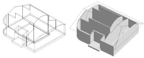
 Creating Walls from
Spaces
Creating Walls from
SpacesFor flexibility in the design process, walls can be created automatically based on existing objects in the drawing including spaces, polygons and shapes. Because of the special relationship between walls and spaces, a dedicated command creates walls from spaces. To create walls from other objects, see Creating Objects from Shapes.
Command |
Path |
|---|---|
Create Walls from Spaces |
AEC > Space Planning |
The Create Spaces from Walls command is available for Vectorworks Landmark and Spotlight software but is not present in those workspaces. To add it to the workspace, see Customizing Workspaces.
Once the floor plan has been developed with multiple spaces, the interior and exterior walls can be automatically created.
To create walls from spaces:
1 Ensure that space objects are present in the drawing. To automatically create walls with a 3D height, specify a delta-Z value for the design layer where the walls will be created.
2 Select the command.
The Create Walls from Spaces dialog box opens. Specify the style of walls to create and their location.
[Filed VB-108528 about spelling of colinear in this dialog box (should be collinear) on 5/20/13. KB. As of 3/27/17 colinear is still misspelled - AP. And still as of 6/14/17- KB.]
► Clique para exibir/ocultar parâmetros.
The available wall styles are defined by wall style resources (see Usando Estilos de Parede).

Exterior and interior walls are applied automatically to the spaces. Round walls approximating the curves are used for Bézier and cubic spline vertices in the space objects.
~~~~~~~~~~~~~~~~~~~~~~~~~
 Creating a Polygon or
Polyline from Walls
Creating a Polygon or
Polyline from WallsCommand |
Workspace: Path |
|---|---|
Create Polys from Walls |
• Architect: AEC • Landmark: Landmark > Architectural • Spotlight: Spotlight > Architectural |
You can create a polygon or polyline based on either the gross area or net area of walls. This is useful for calculating the area of a room, for example, or for using color to differentiate among rooms.
To create a polygon or polyline based on the perimeter of the walls:
1 Select the walls to use for the polygon or polyline. Multiple walls can be selected to create several polygons or polylines at the same time.
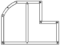
2 Select the command.
The Create Polys from Walls dialog box opens.
► Clique para exibir/ocultar parâmetros.

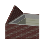
 Criando
Paredes Cortina
Criando
Paredes CortinaTool |
Workspace: Tool set |
|---|---|
• Wall
• Round Wall
|
• Architect and Spotlight: Building Shell • Landmark: Building Shell and Site Planning |
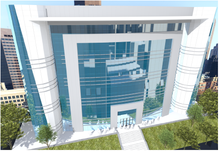
The Wall and Round Wall tools create curtain walls in addition to standard walls. Curtain walls consist of frames that contain panels; often, the panels are made of glass, but they can also be opaque or decorative. The Vectorworks program models the frames, panels, and connections according to real-world architectural standards. Since the curtain wall is based on the Wall tool, it can take advantage of all the benefits of the Wall tool, such as resizing, editing, joining, using walls as the basis of slabs and spaces, bounding by story level, inserting plug-in objects, cut plane appearance, and more. Energy-related information specified for curtain walls is considered when conducting an energy analysis (Vectorworks Architect required). Doors and windows have special capabilities when they are inserted within curtain walls so that all the design elements work together.
|
Click here for a video tip about this topic (internet access required). |
To create curtain walls:
1 Click the tool, and then click the desired control line mode and drawing mode (see Criando Paredes).
2 Do one of the following:
• To use an existing wall style from the resource libraries, click Wall Style from the Tool bar. From the Resource Selector, double-click a resource to activate it. Curtain wall styles begin with the prefix CW for easy identification. Or, to draw an unstyled wall, leave the <Unstyled> setting as is. Proceed to step 5.
• To create a custom wall style, click Preferences. From the Wall Preferences dialog box, set the default properties. The properties can be edited from the Object Info palette.
3 Curtain walls consist of a repeating grid of frames and panels. From the Wall Preferences dialog box, specify the number of horizontal and vertical frames that make up one section of the curtain wall, and then specify the appearance of the frames and the panels within that grid. The defined section is repeated over the length and height of the wall.
Unstyled curtain walls can be drawn first, and the curtain wall parameters can be set later from the Object Info palette by clicking Curtain Wall Grid. The Curtain Wall Grid dialog box opens, to edit the parameters of the unstyled curtain wall. However, editing unstyled walls by this method may clear existing frames and panels, and recreate the curtain wall grid.
► Clique para exibir/ocultar parâmetros.
4 When the curtain wall parameters have been specified, and any changes have been saved as a wall style resource if desired, click OK. A saved or selected wall style is saved as a resource in the file, and displays in the Resource Manager and in the Wall Style list on the Tool bar.
5 If Polygon mode is selected, click at the starting point of the first curtain wall section.
6 Click to end the first wall section.
To continue creating curtain walls, click at the end of each additional wall section.
7 Double-click to finish the curtain wall if the start point and end point are not at the same location; otherwise, click at the starting location (a SmartCursor cue displays) to finish the wall.
Alternatively, after completing all but the final click, press the keyboard shortcut (K by default) to automatically close the polygonal wall network. See Desenhando Paredes Retas.
8 If Rectangle mode is selected, click at the wall’s start point; this becomes one corner of the rectangular wall system. Move the cursor to the opposite corner until the desired size is previewed.
9 Click to set a corner point on the wall system. Four walls are created.

~~~~~~~~~~~~~~~~~~~~~~~~~
 Setting
Curtain Wall Frame Parameters
Setting
Curtain Wall Frame ParametersThe frame settings and appearance are controlled individually for each frame location, for maximum flexibility when setting the frame parameters.
Unstyled curtain walls can be drawn first, and the curtain wall parameters can be set later from the Object Info palette by clicking Curtain Wall Grid. The Curtain Wall Grid dialog box opens, to edit the parameters of the unstyled curtain wall. However, editing unstyled walls by this method may clear existing frames and panels, and recreate the curtain wall grid.
To set the curtain wall frame appearance:
From the Definition tab of the Wall Preferences dialog box, or when editing a curtain wall style, click Frame Settings.
The Frame Settings dialog box opens.
► Clique para exibir/ocultar parâmetros.
The parameters can be edited from the Object Info palette; see Propriedades da Parede. The Cut Plane parameter determines the height for displaying the curtain wall in Top/Plan view.
~~~~~~~~~~~~~~~~~~~~~~~~~
 Setting
Curtain Wall Panel Parameters
Setting
Curtain Wall Panel ParametersThe panel settings and appearance are specified in the Panel Settings dialog box.
If setting up curtain wall preferences, these parameters are available from the Definition tab of the Wall Preferences dialog box. For an existing curtain wall, they are available from the Curtain Wall Grid dialog box.
To set the curtain wall panel appearance:
1 From the Object Info palette of a selected curtain wall, click Curtain Wall Grid.
The Curtain Wall Grid dialog box opens.
2 Click Panel Settings.
The Panel Settings dialog box opens.
► Clique para exibir/ocultar parâmetros.
~~~~~~~~~~~~~~~~~~~~~~~~~
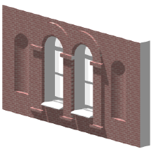
 Creating
Wall Features
Creating
Wall FeaturesOnce a standard round or straight wall has been created, features such as projections and recesses can be added to it. Create wall features from 2D or 3D objects, as well as symbols. By default, 2D objects are extruded to span the height of the wall, but offsets from the top and bottom of the wall can be specified. Use 3D objects, such as sweeps or other solids, to create more complicated features. Use symbols to be able to update multiple instances of a feature with a single edit.
It it not recommended to create wall features that are applied to the entire length of the wall, such as battered walls, or wall caps.
Unlike a symbol, a wall feature is actually part of the wall geometry. A wall feature interacts with the wall components, it renders along with the rest of the wall, and if it was created from a 2D object, it automatically adjusts when the wall height changes. Because wall features interact with wall components, wall features cannot be created for curtain walls.
|
Click here for a video tip about this topic (internet access required). |
~~~~~~~~~~~~~~~~~~~~~~~~~
 Creating Wall
Projections
Creating Wall
ProjectionsCommand |
Workspace: Path |
|---|---|
Create Wall Projection |
• Architect: AEC • Landmark: Landmark > Architectural • Spotlight: Spotlight > Architectural |
To create wall projections:
1 Create the closed 2D or 3D solid object with which to modify the wall. The geometry of the object must define an area or volume that has no self-contacts, no self-intersections, and no edges that fold back on themselves.
2 For a 2D object, simply make sure that the object overlaps the wall, and that the view is Top/Plan. For a 3D object, first create the object at the appropriate height in relation to the bottom of the wall (Z axis); then set the appropriate X and Y axis location so that the object overlaps the wall.
3 With both the wall and the modifier object selected, select the command.
Alternatively, for 2D objects only, select Modify > Add Surface.
The Create Wall Feature Projection dialog box opens; different fields display depending on whether a 2D or 3D modifier object is selected.
► Clique para exibir/ocultar parâmetros.

~~~~~~~~~~~~~~~~~~~~~~~~~
 Creating Wall
Recesses
Creating Wall
RecessesCommand |
Workspace: Path |
|---|---|
Create Wall Recess |
• Architect: AEC • Landmark: Landmark > Architectural • Spotlight: Spotlight > Architectural |
To create a wall recess:
1 Create the closed 2D or 3D solid object with which to modify the wall. The geometry of the object must define an area or volume that has no self-contacts, no self-intersections, and no edges that fold back on themselves.
2 For a 2D object, simply make sure that the object overlaps the wall in Top/Plan view. For a 3D object, first create the object at the appropriate height in relation to the bottom of the wall (Z axis); then set the appropriate X and Y axis location so that the object overlaps the wall.
3 With both the appropriate wall and the modifier object selected, select the command.
Alternatively, for 2D objects only, select Modify > Clip Surface.
The Create Wall Feature Recess dialog box opens; different fields display depending on whether a 2D or 3D modifier object is selected.
► Clique para exibir/ocultar parâmetros.

~~~~~~~~~~~~~~~~~~~~~~~~~
 Wall
Feature Properties
Wall
Feature PropertiesAfter a wall feature has been created, it can be edited from the Object Info palette. Alternatively, right-click on the feature and select Properties from the context menu.
In addition to the parameters available when the feature is created, the following options are available.
► Clique para exibir/ocultar parâmetros.
~~~~~~~~~~~~~~~~~~~~~~~~~
 Editing
Wall Features
Editing
Wall FeaturesSimilar to symbols, the original 2D or 3D object (or symbol) can be edited after the wall feature is created. For example, the location or shape of the object can be changed.
To access the editing mode, double-click the wall feature. Alternatively, right-click on the feature and select Edit from the context menu. To delete the wall feature, delete the original object from which the wall feature was created. Click Exit Wall Feature to exit the editing mode.
Also similar to symbols, wall features can be moved and duplicated in various ways in both straight and round walls. See the following topics:
• Movendo Símbolos em Paredes com a Ferramenta Seleção
• Moving Symbols in Walls with the Move Command
• Movendo Símbolos em Paredes com a Ferramenta Mover por Pontos
~~~~~~~~~~~~~~~~~~~~~~~~~


