 Interoperabilidade
de formato IFCInteroperabilidade
de formato IFC
Interoperabilidade
de formato IFCInteroperabilidade
de formato IFCThe Vectorworks Design Series products support Building Information Model (BIM) interoperability using the Industry Foundation Classes (IFC) data specification and file formats. Vectorworks currently supports versions 2x2, 2x3, and 4, and is certified by buildingSMART International for the export of models based on the IFC2x3 Coordination View 2.0 - Architecture model view definition, as well as import of any IFC2x3 Coordination View 2.0 model.
IFC is an open standard, developed and maintained by buildingSMART International, for building data that permits information to be shared and maintained throughout the life cycle of the construction project: design, analysis, specification, fabrication, construction, and occupancy.
The capabilities and usage for IFC data standards are still evolving. However, objects and models containing IFC data have been proven to be a useful part of the design process. Some examples of the use of IFC data include:
• Collaborative design, where an architect exports an architectural model to a structural engineer for analysis and design, and then imports the structural model, in an IFC format, for coordination purposes
• Energy performance simulation and analysis of a building envelope and systems
• Automated analysis of code compliance
• Space planning and space inventory analysis
Central to the concept of IFC is the idea of “semantic objects.” Like Vectorworks plug-in objects, IFC objects are more than just collections of geometry; they have a meaning within the building fabric itself, be it as a door, a wall, a window, or a handrail.
The following Vectorworks plug-in objects are automatically converted upon export to the IFC object types shown. Most content in the Vectorworks Architect, Landmark, and Designer symbol libraries have default IFC tags, as well. You can edit the default IFC assignments as needed.
Base Cabinet [IfcFurnishingElement] |
Bath-Shower [IfcFlowTerminal] |
Ceiling Grid [IfcCovering] |
Clothes Rod [IfcFurnishingElement] |
Column [IfcColumn] |
Comm Device [IfcDistributionFlowElement] |
Compartment Sink [IfcFlowTerminal] |
Counter Top [IfcFurnishingElement] |
Curtain Wall (Straight & Curved) [IfcCurtainWall] |
Curtain Wall Frames [IfcMember] |
Curtain Wall Panels [IfcPlate] |
Desk [IfcFurnishingElement] |
Door [IfcDoor] |
Drilled Footing [IfcFooting] |
Elevator [IfcTransportElement] |
Escalator [IfcTransportElement] |
Fireplace [IfcDistributionFlowElement] |
Floor [IfcSlab] |
Framing Member [IfcMember or IfcBeam] |
Grab Bars [IfcRailing] |
Guardrail (Curved & Straight) [IfcRailing] |
Handrail (Curved & Straight) [IfcRailing] |
HVAC Damper [IfcDistributionFlowElement] |
HVAC Diffuser [IfcDistributionFlowElement] |
HVAC Elbow Duct [IfcDistributionFlowElement] |
HVAC Flex Duct [IfcDistributionFlowElement] |
HVAC Outlet [IfcDistributionFlowElement] |
HVAC Splitter [IfcDistributionFlowElement] |
HVAC Straight Duct [IfcDistributionFlowElement] |
HVAC Transition [IfcDistributionFlowElement] |
HVAC Vertical Duct [IfcDistributionFlowElement] |
HVAC Vertical Elbow [IfcDistributionFlowElement] |
Incandescent Fixture [IfcDistributionFlowElement] |
Massing Model (on layer mapped to site) [IfcBuilding] |
Mullion [IfcMember] |
Parking Spaces [IfcSpace] |
Pilaster [IfcColumn] |
Pillar [IfcColumn] |
Piping Run [IfcDistributionFlowElement] |
Plant [IfcBuildingElementProxy] |
Ramp [IfcRamp] |
Receptacle [IfcDistributionFlowElement] |
Roadway (all types) [IfcTransportElement] |
Roof [IfcRoof containing instances of IfcSlab] |
Roof Face [IfcSlab] |
Seating Layout [IfcFurnishingElement] |
Round Wall [IfcWall or IfcWallStandardCase] |
Site Model [IfcSite] |
Shelving Unit [IfcFurnishingElement] |
Slab [IfcSlab] |
Space [IfcSpace] |
Stair (including Simple and Custom) [IfcStair] |
Switch [IfcDistributionFlowElement] |
Table [IfcFurnishingElement] |
Tables and Chairs [IfcFurnishingElement] |
Toilet Fixture [IfcFlowTerminal] |
Utility Cabinet [IfcFurnishing Element] |
Wall [IfcWall or IfcWallStandardCase] |
Wall Cabinet [IfcFurnishingElement] |
Window [IfcWindow] |
Workstation Counter [IfcFurnishingElement] |
Workstation Overhead [IfcFurnishingElement] |
Workstation Panel [IfcFurnishingElement] |
Workstation Pedestal [IfcFurnishingElement] |
Use the Data tab of the Object Info palette (or the IFC Data command) to edit the object types and properties assigned to objects so that other applications that read your exported IFC files can properly identify each object. You can also use the IFC Data Mapping command to further customize the transfer of data from Vectorworks objects to IFC objects.
When an IFC file is imported into a Vectorworks file, IfcSpace objects are translated into the corresponding Vectorworks Space object. However, all other objects are imported into the Vectorworks file as a plug-in object called an “IFC Entity.” [Robert says this may change in v2018 SP 3 or 4 when we start to support a new “DTV” protocol 8/17 KB] The semantic definition of the IFC Entity—IfcColumn, IfcWall, IfcWindow, for example—is maintained and displayed. Like a group or symbol, an IFC Entity can contain an arbitrary collection of geometry, usually generic or constructive solid (CSG), but like a plug-in object, it can be inserted into walls and has sets of data and properties attached. With this generalized import capability, the Vectorworks program can import any kind of object supported by the IFC data standard.
For more information about BIM and IFC support in Vectorworks, visit the Vectorworks website.
~~~~~~~~~~~~~~~~~~~~~~~~~
 Fluxo de Trabalho: Exportação IFC
Generally, IFC-compatible applications are set up to work with an entire project (sites with buildings consisting of stories) in a single file. When you select the Export IFC Project command, you assign design layers to building stories for meaningful export (Vectorworks Architect required). For a project initially set up with stories, mapping is done automatically so that the layers assigned to the building stories are automatically included in the Mapped Layers list and are mapped to an appropriately named IFC Story. Mapping can also be controlled manually, allowing you to override or edit the automated process or make any subsequent changes. The Import IFC command automatically assigns each IFC building story to its own design layer.
To make Vectorworks building models easy to export to IFC, the following guidelines may be useful:
• Set up the project initially with stories as described in Setting Up the Building Structure with Stories (Vectorworks Architect required).
• Design layers for the building model should correspond to building stories (Vectorworks Architect required), not categories of information. (Use classes for categorization.)
• Take care to set up the elevation values of layers correctly, and verify that all the objects in the drawing are correctly aligned vertically. Examining the project in Unified View mode makes this much easier.
• Use standard Vectorworks plug-in objects listed in Interoperabilidade de formato IFC wherever possible; the IFC data are already attached to these objects.
• Use the IFC Data command to attach IFC data to custom user-defined hybrid or 3D symbols, custom 3D elements, or auto-hybrid objects, so that they will be recognized at IFC export.
• Manage the IFC data with the IFC Data Mapping command, attaching IFC data sets to objects that do not already have them, selecting objects and property sets for export, and defining mapping formulas. See Mapping IFC Data.
• Set up project data in the IFC Export dialog box (see Exporting IFC Projects), and save the settings for use when creating reports. No actual export is needed before running IFC and COBie reports based on the data.
• Use the Create Report command to generate default IFC or COBie schedules, or create your own schedules to verify and correct the IFC data attached to objects. See Creating IFC and COBie Reports.
• Test the quality of the IFC export file by verifying it in an IFC model viewer. Almost all IFC viewers can traverse the IFC hierarchical “tree” structure to view and validate the model.
For information about available IFC viewers and other IFC-compatible applications, visit the buildingSMART IFC-Compatible Implementations Database website or IfcWiki.org.
• If you receive comments or corrections for the project in BIM Collaboration Format (BCF), use the Open BCF Manager command to view the notes, and then correct the project file (see Managing BCF Information).
~~~~~~~~~~~~~~~~~~~~~~~~~
 Atribuindo Dados IFC a Objetos
Command |
Workspace: Path |
|---|---|
IFC Data |
• Architect: AEC • Landmark: Landmark > Architectural • Spotlight: Spotlight > Architectural |
When a building project is exported to an IFC file, Vectorworks plug-in objects and pre-assigned symbols are automatically assigned to IFC entities. The attached IFC data display on the Data tab of the Object Info palette.
Simple hybrid or 3D geometric objects are not exported unless you assign IFC data to them prior to export, from the Data tab of the Object Info palette or with the IFC Data command. IFC data can also be included or excluded from export with the IFC Data Mapping command.
Assigning IFC data to an object does not alter it in any visible way. The object can still be edited with standard Vectorworks tools and commands. An example of this would be to use a floor or slab object to model a flat ceiling. Select the floor or slab in the model, and then select the IFC Data command. From the list in the Select IFC Object dialog box, select IfcCovering, the correct assignment for a ceiling. Then, in the IFC Data dialog box, select CEILING from the PredefinedType list in the Properties for the selected Data Set lists.
The IFC Zones, Systems and Groups command attaches IFC data to space zones, systems, or groups. See Assigning IFC Data to Zones, Systems, and Groups.
An object can also be “wrapped” in a container so that it is identified in the Vectorworks file as an IFC Entity object. Editing an IFC Entity is less direct than editing simple Vectorworks objects with IFC data attached. For this reason, an IFC Entity can be useful for model elements that need to be secured from casual changes.
To assign IFC data:
1 Select the object, group, symbol instance, or symbol definition for assignment of IFC data. More than one item can be selected at one time.
IFC data applied to symbol instances affect only the selected instances, not all instances. To attach IFC data to a symbol definition, locate the symbol definition in the Resource Manager. Right-click the symbol and select IFC Data from the context menu. This attaches the IFC data to future symbol placements, and to any current instances that do not have IFC data already attached to them.
2 Select the command.
Alternatively, select Show IFC Data from the Coordinate/IFC menu on the Object Info palette to enable IFC-related information to display on the palette, and then click Attach IFC from the Data tab of the Object Info palette.

The Select IFC Object dialog box opens, listing available IFC object types.
► Click to show/hide the parameters.
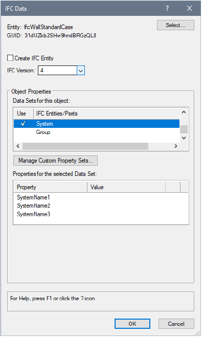
The IFC Data dialog box opens.
The property sets of objects with IFC data and IFC entities can be mapped and saved in mapped sets as described in Mapping IFC Data. To use the assigned mapping, select the “by style” data mapping option; to specify a custom mapping for a specific object, select “by instance” for the data set property.
► Click to show/hide the parameters.
The Data tab of the Object Info palette displays the selected IFC object or entity information when Show IFC Data is enabled on the palette. Objects with default IFC data assigned display with <Default> to indicate that the default IFC data have not been modified.
The geometry of IFC entities can be edited with the Modify > Edit IFC Entity command; alternatively, right-click on the IFC entity and select Edit from the context menu.
~~~~~~~~~~~~~~~~~~~~~~~~~
 Assigning
IFC Data to Zones, Systems, and Groups
Assigning
IFC Data to Zones, Systems, and GroupsCommand |
Workspace: Path |
|---|---|
IFC Zones, Systems and Groups |
• Architect: AEC • Landmark: Landmark > Architectural • Spotlight: Spotlight > Architectural |
The IFC Zones, Systems and Groups command attaches IFC data to the specified IFC zones from the current file. In addition, new systems and groups can be created, with IFC data attached.
Zones are assigned to space objects from the Occupancy pane of the Space Settings dialog box (see Space Settings: Occupancy Pane).
The system or group can then be attached as a Data set, with the new system or group among the Pset choices for the data set.
The IFC Zones, Systems and Groups command is available for Vectorworks Landmark and Spotlight software but is not present in those workspaces. It can be added to the Landmark and Spotlight workspaces (see Customizing Workspaces).
To attach IFC data to zones in use in the file:
1 Select the command.
The IFC Zones, Systems and Groups dialog box opens.
2 Click the Zones tab.
Zones in use in the file are listed.
3 Select a zone and click Edit. Only one zone can be selected at a time.
4 The IFC Data dialog box opens. The object type is automatically set to ifcZone, and the property Name value is set to the zone name. See Atribuindo Dados IFC a Objetos.
At IFC export, the IFC zone data is automatically applied to all space objects with a matching zone definition.
To create new systems or groups and attach IFC data:
1 Select the command.
The IFC Zones, Systems and Groups dialog box opens.
2 Click the Systems or Groups tab.
Systems or groups in use in the file are listed.
3 Click New to create a new system or group.
4 Provide a name for the new system or group and click OK.
5 The IFC Data dialog box opens. The object type is automatically set to ifcSystem or ifcGroup, and the property Name value set to the system or group name.
6 Click OK to attach the IFC data to the system or group.
The new system or group is added to the list, and when assigning a system or group data set, the system or group name is available from the list.
Select the system or group, and click Edit to make any changes to the attached IFC data. Click Delete to remove the selected system or group.
~~~~~~~~~~~~~~~~~~~~~~~~~
 Viewing
and Editing IFC Data
Viewing
and Editing IFC DataThe data attached to Vectorworks objects or IFC entities, whether created in the Vectorworks program or imported from an IFC file, can be viewed and edited from the Data tab of the Object Info palette or with the IFC Data command. In addition, the default IFC object data that corresponds to a Vectorworks plug-in object, such as a Space object, window, or wall, can be viewed.
To access IFC data:
1 Select the Vectorworks object or IFC entity. Multiple items can be selected; edits apply to all eligible objects in the selection.
2 Click the Data tab from the Object Info palette to view and edit attached IFC data. (If the data do not display, select Show IFC Data from the Coordinate/IFC menu on the Object Info palette.)
3 Place a check mark next to a property set that should be attached to the object or IFC entity. At the bottom portion of the Data tab, the parameters of the selected property set are displayed and, where permitted, they are editable. Properties can be set by instance or by mapping according to the settings made when Mapping IFC Data. When IFC data mapping has suppressed the export of a property set, it displays with an X.
Selected attached property sets can be removed by deselecting the check mark, or clicking Delete from the Data tab. (The entire selected IFC data set can be removed from the selected object by clicking Delete.)
Custom property sets can be defined from record formats for attached, non-default IFC data. In this case, the Custom pSets button is available for Using Custom IFC Property Sets.

Command |
Workspace: Path |
|---|---|
IFC Data |
• Architect: AEC • Landmark: Landmark > Architectural • Spotlight: Spotlight > Architectural |
1 Select the Vectorworks object or IFC entity. Multiple items can be selected; edits apply to all eligible objects in the selection.
2 Select the command.
3 If you have selected a group that contains objects with multiple IfcObjectTypes, the Choose IFC Type dialog box opens. Select the IFC Type to apply to the group. Optionally, remove the IFC data from the contained objects.
4 When the items to be edited have been specified if necessary, the IFC Data dialog box opens. View or edit the IFC data as described in Atribuindo Dados IFC a Objetos.
If an IFC entity is selected, the IFC Data dialog box displays the data attached to the entity as described in Atribuindo Dados IFC a Objetos; the data can be edited. If a Vectorworks plug-in object is selected, the IFC Data dialog box displays the corresponding IFC Object type. At export, the object will be converted to that type of entity.
~~~~~~~~~~~~~~~~~~~~~~~~~
 Using Custom IFC Property Sets
Property sets (Pset_XxxxXxxx) are used to assign groups of individual data fields, or properties, to IFC entities. Property sets can be very specific to an IFC entity, such as Pset_WallCommon to IfcWall, or more generally applied to any IFC entity, such as Pset_ManufacturerTypeInformation. Some property sets and their values are explicitly predefined and listed in the IFC specification; the naming convention Pset_Xxx applies to these officially specified property sets.
In addition to these specific predefined property sets that are part of the standard IFC schema, information can be attached to a symbol definition as a record format; this record format data can be used as a custom property set for IFC.
Due to the extensible nature of IFC, any user-defined data, even when not explicitly identified in the IFC specification, can still be captured and exchanged using custom property sets. Custom property sets must follow technical encoding conventions. They must have unique and allowable names; the names cannot duplicate specified property set names or begin with “Pset_.”
To make collaboration easier, the Vectorworks Software Developer’s Kit (SDK) has functions to create a custom property set either programmatically, or by importing an XML file that defines the property set. For detailed developer-oriented documentation related to the SDK, see developer.vectorworks.net.
Additionally, you can create custom IFC property sets in Vectorworks Design Series products as described in the following topics.
To use a custom property set, first create the record format to define the data to be captured and exchanged in IFC format. The record format name becomes the name of the custom property set. Record formats designated for IFC export should be named with a VwPset_ or ePset_ prefix, or use a name that is defined by a specific Model View Definition (MVD) or documented model Exchange Requirement (ER). Record format names are case sensitive, and should not contain blank spaces (use an underscore if needed). For example, you might use a record format named “ePset_MyData.”
The record format can consist of any number of fields, designated by a Field Name and a Field Type; see Creating Record Formats. The field types are automatically converted to equivalent IFC value types. For example:
Field Type |
IFC Value Type |
|---|---|
Integer |
IfcInteger |
Boolean |
IfcBoolean |
Text |
IfcText |
Number |
IfcReal |
To use more specific IFC value types, see Using Custom IFC Value Types.
Default field values are ignored when the record format is converted to an IFC property set. Therefore, leave the default value empty for Integer, Boolean, Text, and Pop-up field types; for Number field types, enter 0 (zero) as the default.
The record format displays in the Resource Manager, in the Record Format category. Like any resource, it can be shared between files using the export or import functionality of the Resource Manager.
Once the custom record format has been created, convert it to an IFC Property Set and attach the data to an object, group, symbol definition, or symbol instance.
A custom Pset can also be assigned when Mapping IFC Data.
In addition to custom record formats that you may have created, existing record formats containing Pset data, such as those attached to BIMobjects, can be selected for use.
To assign the custom IFC data:
1 Select the object, group, or symbol for assignment of IFC data.
2 From the Data tab of the Object Info palette, locate the attached IFC data (or click Attach IFC to attach it). When non-default IFC data is attached, click Custom pSets.
Alternatively, use the IFC Data command to specify the IFC object type as described in Atribuindo Dados IFC a Objetos. From the IFC Data dialog box, click Manage Custom Property Sets.
The Manage Custom Property Sets dialog box opens.
3 Click the Use column to select one or more record formats. Selected record formats display with a check mark.
4 Click OK to return to the Object Info palette or the IFC Data dialog box.
The selected custom record formats are listed as data sets in the IFC Entities/Psets list.
5 Select the custom Pset from the Data tab and click to give it a check mark (or if in the IFC Data dialog box, place a check mark in the Use column.) A check mark indicates that the Pset is enabled and attached to the object.
If you remove the check mark from a custom Pset, the record is not applied to the object, but the record remains in the object’s Psets list. To remove it, select it from the Data tab and click Detach. If you are in the IFC Data dialog box, click Manage Custom Property Sets, and remove the check mark from the Use column. When prompted, click OK to confirm that you want to delete the Pset from this object.
6 The bottom portion of the Object Info palette (or pane if in the IFC Data dialog box) displays the properties associated with the custom Pset. Select each property and assign a value to it.
Select the object for Viewing and Editing IFC Data from the Data tab of the Object Info palette.
The custom property set is saved in the current file. To use a custom property set in another file or project, export the record format to another file and repeat these steps to attach IFC data to objects.
If the IFC Value Types that are automatically assigned to your custom fields are not specific enough, you can pair each field in your custom record format with a field that identifies the IFC value (IfcValue) type for that field. Each pair must have the same field type.
For example, you might have three fields in a custom record format that contain the following information about a set of objects:
• Product code (such as AB-124)
• Whether the object is on the schedule (true or false)
• Cost per unit (such as 75.00)
For each field that contains object data, create a companion field that indicates the IFC value type of the data. In this example, you would have a total of six fields in the record format:
Field Pairs |
Type |
|---|---|
ProductCode IfcIdentifier |
Text Text |
OnSchedule IfcBoolean |
Boolean Boolean |
UnitCost IfcReal |
Number Number |
For simple fields (Text/Boolean/Number), if you specify a record without the companion fields, the Type is taken from the record field Type.
Choose an IFC value type and record format field type appropriate for the kind of information being captured by the field, such as a simple number, a TRUE/FALSE choice, a text string or simple label, or a measurement. In the Vectorworks program, allowable types include Integer, Boolean, Text, or Number. The Field Name identifying an IFC value type should be based on the IFC specification for the different defined types of values (IfcValue), as shown in the following list.
IFC Value Types |
Vectorworks Record Format Field Type and Description |
|---|---|
IfcSimpleValue |
These are the most common and cover most user cases |
IfcInteger |
Integer: a simple whole number ranging from -32,768 to 32,767 |
IfcReal |
Number: General or Decimal |
IfcBoolean |
Boolean: also known as TRUE or FALSE |
IfcLogical |
Boolean: similar to Boolean, but can include a value of “UNKNOWN” |
IfcIdentifier |
Text: a simple text ID string, usually a mix of alphanumeric characters and symbols |
IfcLabel |
Text: a simple text name string, usually a mix of alphanumeric characters |
IfcText |
Text: a descriptive text field string of up to 255 characters |
IfcMeasureValue |
A complete list can be found in the IFC specification |
IfcAreaMeasure |
Number: Dimension Area |
IfcLengthMeasure |
Number: Dimension |
IfcMassMeasure |
Number: General or Decimal |
IfcThermodynamicTemperatureMeasure |
Number: General or Decimal |
IfcTimeMeasure |
Integer or Number: General |
IfcVolumeMeasure |
Number: Dimension Volume |
IfcDerivedMeasureValue |
A complete list can be found in the IFC specification |
IfcEnergyMeasure |
Number: General or Decimal |
IfcIlluminanceMeasure |
Number: General or Decimal |
IfcPowerMeasure |
Number: General or Decimal |
IfcThermalTransmittanceMeasure |
Number: General or Decimal |
IfcTimeStamp |
Integer or Number: General |
IfcLuminousIntensityDistributionMeasure |
Number: General or Decimal |
~~~~~~~~~~~~~~~~~~~~~~~~~
 Mapping IFC Data
Command |
Workspace: Path |
|---|---|
IFC Data Mapping |
• Architect: AEC • Landmark: Landmark > Architectural • Spotlight: Spotlight > Architectural |
In a BIM project, you may wish to control whether specific objects and symbol definitions are exported to IFC. The property sets of specific objects can also be controlled prior to export, so export filtering can occur at the object or property set level. In addition, external data attached to objects may need to be mapped to their IFC equivalent prior to export. You can define, save, and restore multiple custom mapping sets for a document. Selected IFC object instances can use or not use the mapping.
Here are some examples of when IFC data mapping is useful.
• You need to add data to an object’s default IFC assignment.
Many Vectorworks objects contain user-defined data that is not included as part of the default IFC assignment. For example, a type designation or acoustic rating for a door will be user-defined data within the door object. These parameters can be mapped to the corresponding IFC parameter values. Mapping allows you to attach property and data set information to objects in addition to the default IFC data.
• You need to map data from a custom record format to an IFC property set.
In Vectorworks, custom data is attached to objects (default objects, plug-in objects, and custom modeled objects) using record formats. The parameters of a custom record format can be mapped to the correct, corresponding IFC property set. For example, a local code or specification system may be attached to an object through a custom record. The parameters for these records can be mapped to the identified, IFC Classification data set to ensure that the data is transferred during an IFC model exchange.
• You need to attach a default IFC assignment and property sets to custom modeled objects or symbols.
IFC assignments and property sets can be defined for all custom-made objects, ensuring that each time the custom object is placed in the file, it will receive the appropriate IFC tag assignment.
To map IFC data:
1 Select the command.
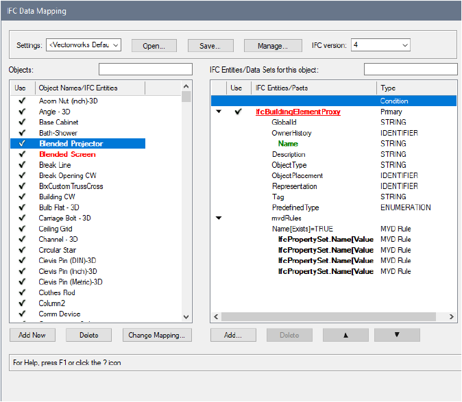
The IFC Data Mapping dialog box opens.
► Click to show/hide the parameters.
2 Assign IFC data to any objects or symbol definitions that do not have any, set objects and property sets that should not export to IFC, and/or define mapping formulas.
|
Click here for a video tip about this topic (internet access required). |
~~~~~~~~~~~~~~~~~~~~~~~~~
 Validating
IFC Data Mapping
Validating
IFC Data MappingTo validate the current mapping settings against an MVD definition:
1 From the IFC Data Mapping dialog box, click Open.
2 Locate and select the .mvdxml file for the MVD you want to validate against. In the IFC Data Mapping dialog box, all objects and property sets that have rules and requirements in the MVD file have bold formatting. Mandatory fields that have no data mapping display in red.
3 At the bottom of the IFC Entities/Psets list, the “mvdRules” section provides information about what data is missing. Click on each MVD rule with bold highlighting to display the mapping requirements in the pane on the right side of the dialog box.
4 Correct the mapping as needed. When an item is valid, its color changes to green. When an MVD rule has been satisfied, the bold formatting is removed.
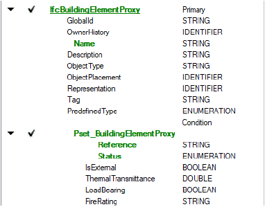
In the following example, after the .mvdxml file has been opened, the Blended Projector and Blended Screen objects are highlighted in red in the Objects list, because they are missing some data. For the Blended Projector, the IfcBuildingElementProxy entity is highlighted in red, and the Name field is highlighted in green.
At the bottom of the IFC Entities/Psets list, the MVD rules indicate that, since a Name field exists, an IfcPropertySet is required.
Click the first rule to see the first mapping requirement for the Name field.
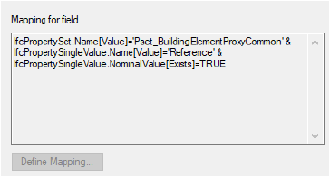
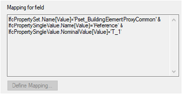
The mapping requires a property set called Pset_BuildingElementProxyCommon, and a Reference field. Click Add and add the Pset. Once added, the Pset has two fields that are not mapped, displayed in red: Reference and Status.
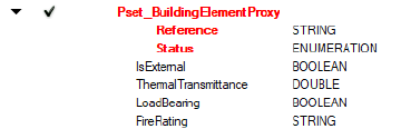
Click the second rule to see that the Reference field should have the value ‘T_1’; click the field and define the mapping.
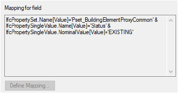
Click the fourth rule to see that the Status field should have the value ‘EXISTING’; click the field and define the mapping.
All the red items now display green, and the Blended Projector mapping is valid.
 Creating
or Editing Mapping Formulas
Creating
or Editing Mapping FormulasUse formulas in the IFC mapping settings to provide more detailed control over the data that is exported for drawing objects. Field mapping formulas adjust the data for the selected object in specific IFC entity and Pset fields. Conditional mapping formulas assign IFC entities and Psets to the selected object based on specific conditions.
As described in more detail in IFC Data Mapping Expressions, a mapping formula contains expressions with constants, variables, operators, and functions. A variable is a data source from Vectorworks, such as an object parameter, record field, class name, or style data. Functions can be math functions, string manipulation functions, conditional, and selector functions.
Use conditional mapping formulas for situations where objects do not have a simple one-to-one correspondence with a specific IFC entity or property set.
• Some plug-in objects should be assigned to different IFC entities, depending on what the object’s settings are, or what the object’s “style” is. For example, a framing member object could be IfcBeam, IfcMember, or IfcColumn.
• Aggregate objects generate more than one IFC entity. For example, a curtain wall object should be assigned to the IfcCurtain wall entity primarily, but its member and plate sub-elements should be assigned to the IfcMember and IfcPlate entities.
• In some situations, different property sets might be assigned to an object, depending on conditions. [Add an example for this? -- tlh 8/1/2018]
For an IFC entity, a conditional formula should yield a specific IFC entity to be used for the object; if the result is empty or a non-valid IFC type, the object will not be exported. For a property set, the formula should yield a true or false value; if the value is false or if there is no result, the property set will not be exported.
IFC field mapping formulas calculate and display the values of certain property set parameters, to map standard BIM data to IFC-compliant data, or to map custom property sets.
• In the IFC Data Mapping dialog box, select a field associated with an object to display the mapping formula on the right side of the dialog box.
• In the IFC Data dialog box, the mapping formula displays in the Data Source parameter of the selected property (see Atribuindo Dados IFC a Objetos).
Study the default data mapping formula to help you understand the data source of the mapped IFC values. Then use IFC Data Mapping Expressions to customize the default formula.
To create a mapping formula:
1 From the IFC Data Mapping dialog box, select the object, and then select the field or condition to map. The current formula displays in the pane on the right side of the dialog box. Here is an example:

2 Click Define Mapping or Define Condition.
The Define Mapping or Define Condition dialog box opens.
Minor syntax edits can be made directly to the formula. For example, add a prefix and/or suffix, or add concatenation or arithmetic operations to the formula. See Entering Formulas in Worksheet Cells for information about arithmetic operations.
► Click to show/hide the parameters.
3 Build the formula by selecting the mapping values and specific parameters from the lists.
The mapping formula displays in the IFC Data Mapping dialog box.
~~~~~~~~~~~~~~~~~~~~~~~~~
 IFC Data Mapping Expressions
Each formula consists of one or more expressions from the following list. The expressions are described in more detail in the rest of this section.
Expression |
Description |
|---|---|
Constants |
Types of data, such as integers, Boolean constants, numbers, and text constants |
Fixed values |
Text strings, numerical and logical values, and so on |
Operators |
Addition, subtraction, comparison, and so on |
Variables |
Vectorworks data sources, such as object parameters, style information, class name |
Functions |
Mathematical functions, string manipulations, conditional functions, and more |
ELSE |
Method of adding alternative data mapping, if the previous one yields an empty value |
Constant |
Description |
Examples |
|---|---|---|
Boolean |
Values are used for Boolean parameters, and are either true or false, written as string constants enclosed within apostrophes |
‘FALSE’ ‘TRUE’ |
Integer |
Positive or negative numbers and 0, written as numbers with no decimal point or apostrophes |
4 125 |
Rational number |
Real number values, written as a number with a decimal point and no apostrophes |
3.14 -12.0 248.141539 |
Text |
String values enclosed within apostrophes |
‘Unstyled Wall’ ‘INTERNAL’ ‘NOTDEFINED’ |
Operator |
Description |
|---|---|
+ |
Unary Plus |
- |
Unary Minus |
+ |
Binary Plus, Addition, Concatenation |
- |
Binary Minus, Subtraction |
* |
Multiplication |
/ |
Division |
= |
Logical EQUALS |
! |
Logical NOT |
| |
Logical OR |
& |
Logical AND |
!= |
Logical NOT EQUAL |
> |
Greater than |
< |
Less than |
>= |
Greater than or equal |
<= |
Less than or equal |
Variables represent sources of data from Vectorworks. They can be combined with constants, function results, and other variables by using operators. The variable type (name) is the same as that of the data source type. Variables are enclosed by square brackets, since spaces are permitted in the name.
Variable |
Format |
Example |
|---|---|---|
Parameters from an object |
[Object.NameOfTheParameter] |
[Object.Config] [Object.Column ID] [Object.Struct Type] |
Vectorworks name |
[Object.VW_Name] |
[Object.VW_Name] |
Record field data from a record format |
[Record.NameOfTheRecord.NameOfTheField] If a record by that name is not attached to the object, then the default value of the record field is taken as the value of the variable. |
[Record.MyRecord.Price] [Record.Plant Record.Latin Name] |
Data from style |
[Style.NameOfTheField] Currently supported data fields are: Name (the name of the style), Mark, Function, Description, Exterior (Boolean), Load-Bearing (Boolean), Fire Rating, Combustible Construction (Boolean), Compartmentation (Boolean), U-Value, Acoustic Rating, Cost Index System, Cost Index Code, Model, Manufacturer. |
[Style.Function] [Style.Name] [Style.Fire Rating] |
Class name |
[ClassName] |
[ClassName] |
Layer name |
[LayerName] |
[LayerName] |
Story name |
[StoryName] |
[StoryName] |
Function |
Description |
|---|---|
PI ( ) |
Returns the number |
SIN (radians) |
Returns the sine |
COS (radians) |
Returns the cosine |
ABS (number) |
Returns the absolute value |
SQRT (number) |
Returns the square root |
IF (logical_expression, value_expression1, value_expression2) |
Calculates logical_expression and returns the calculated value of value_expression1, if TRUE, or value of the value_expression2, otherwise |
SELECT1 (number_expression, value_expression1, value_expression2, …, value_expressionN) |
Calculates number_expression and returns the calculated value of value_expression1, if the result is 0, value of the value_expression2, if the result is 1 and so on. Returns the value of the last expression, if the result is bigger than N-1. The number of the function parameters must be 3 or more. |
SELECT2 (logical_expression1, value_expression1, logical_expression2, value_expression2, …, logical_expressionN, value_expressionN) |
Calculates the first logical expression and returns the calculated value of value_expression1, if the result is TRUE; otherwise, continues with the next logical expression and value expression pair. The number of the function parameters must be even, and greater than 2. |
COUNTER (“name”) |
Returns auto-incremented values (for generating unique values) |
BOUNDS (“name”) |
Returns X-, Y-, Z-, or Width/Height/Depth dimensions of an object |
LEFT (text, count) |
Returns the left side of the string, using the specified count of characters. Returns an empty string if the count value is incorrect. |
RIGHT (text, count) |
Returns the right side of the string, using the specified count of characters. Returns an empty string if the count value is incorrect. |
MID (text, index, count) |
Returns the right side of the string, split by the position index (0 is the position of the first character) and using the specified count of characters. Returns an empty string if the index or count values are incorrect. |
FIND (subtext, text) |
Returns the zero-based position of subtext in text, if found, or -1 if not found. Example: example FIND (‘fo’, ‘foo’) returns 0 and FIND (‘oo’, ‘foo’) returns 1. |
LEN (string) |
Returns the length of the string |
INSERT (string1, index, string2) |
Inserts string2 in string1 at the given position index |
DELETE (string, index, count) |
Removes the right side of the string, split by position index and having the specified count of characters |
REPLACE (string1, string2, string3) |
In string1, replaces all occurrences of string2 with string3 |
TRIMLEFT (string) |
Returns the left trimmed string from whitespaces |
TRIMRIGHT (string) |
Returns the right trimmed string from whitespaces |
MAKEUPPER (string) |
Returns the uppercase string |
MAKELOWER (string) |
Returns the lowercase string |
~~~~~~~~~~~~~~~~~~~~~~~~~
 IFC
Data Mapping Examples
IFC
Data Mapping Examples[Add a conditional IFC entity/Pset mapping example here? -- tlh 8/2/2018]
File exchange scenarios frequently include requirements and policies specifying that certain data fields must not be empty, or that every data field needs to have a default value. Only a couple of specific objects have a different value that will be overridden manually. To be certain that a mandatory data field always contains a value, simply include a constant at the end of the data mapping formula.
[Style.Function] ELSE ‘NOTDEFINED’
[Object.VW_Name] ELSE [Style.Name] ELSE ‘Roof’
To handle a case with a default value for most of the objects, but different values for only some specific objects, it is good practice to create a record format, and include a default record field value that becomes the default value of the data source. Then, attach that record only to the objects that will have the specifically different values, and change the value in the attached records as necessary. Objects with no such record attached will get the default value and the objects with that record attached will get the specific value.
[Record.Pricing Details.Discount];
The results of a data mapping formula often need to be “enhanced” to improve legibility, to add a prefix/suffix to meet certain requirements, or to be combined or calculated from multiple sources.
In this example, we need a better description of an escalator, including important information about the manufacturer and the step width. We also want to add some words to increase the legibility.
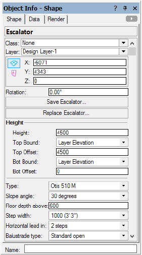
'Escalator: ' + [Object.Type] + ' Width: ' + [Object.Step width]
Escalator: Otis 510 M Width: 1000 (3' 3")
In another example, we need to set up the name of the window object to come from the Vectorworks name. If there is no Vectorworks name, we want to combine ID Prefix, ID Label, and ID Suffix fields. If all of those parameters are empty, the word “Window” should be used to identify the window.
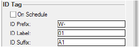
[Object.VW_Name] ELSE [Object.IDPrefix] + [Object.IDLabel] + [Object.IDSuffix] ELSE 'Window'
W-01A1
In this example, we want to calculate the IfcWindow.OverallHeight based on the settings of our window object.
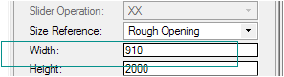
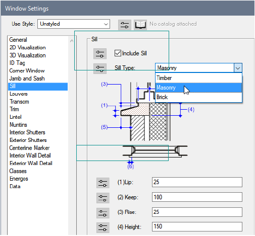
The Height parameter contains the correct value, as long as the window has no sill or, if it has a sill, it is a Brick Sill type. In any other situation, the Sill Height (3) value needs to be added to the window Height.
[Object.OverallHeight] + IF([Object.IncludeSill] & ([Object.SillStyle] != 'Brick'),[Object.SillHeight], 0)
2000.0
2150.0
IFC data requires many “enumeration” kinds of data fields. Typical examples include: PredefinedType, OperationType, ShapeType, and so on. Sometimes, there is no one-to-one correspondence; the current settings differ from IFC, no valid data sources can be mapped directly, or the values are written in another language.
In this example, we will map the Sash Operation list from the window to the required OperationType of the IFC Window Panel data set.
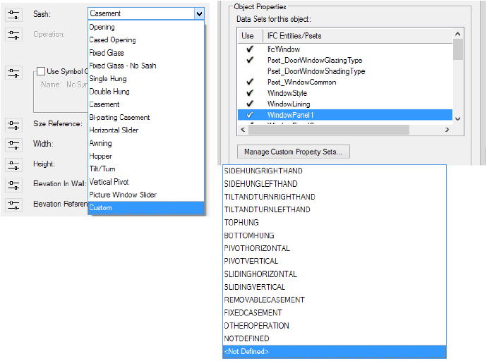
For the mapping, we will use one of the selector functions, which maps the window Sash Operation list entries to a pair of IFC Window Panel parameters (logical and value):
SELECT2([Object.SashOperation] = 'Opening', 'FIXEDCASEMENT',
[Object.SashOperation] = 'Cased Opening', 'FIXEDCASEMENT',
[Object.SashOperation] = 'Fixed Glass', 'FIXEDCASEMENT',
[Object.SashOperation] = 'Fixed Glass - No Sash', 'FIXEDCASEMENT',
[Object.SashOperation] = 'Single Hung', 'SLIDINGVERTICAL',
[Object.SashOperation] = 'Double Hung', 'SLIDINGVERTICAL',
[Object.SashOperation] = 'Casement', 'SIDEHUNGLEFTHAND',
[Object.SashOperation] = 'Bi-parting Casement', 'SIDEHUNGLEFTHAND',
[Object.SashOperation] = 'Horizontal Slider', 'SLIDINGHORIZONTAL',
[Object.SashOperation] = 'Awning', 'TOPHUNG',
[Object.SashOperation] = 'Hopper', 'BOTTOMHUNG',
[Object.SashOperation] = 'Tilt/Turn', 'TILTANDTURNLEFTHAND',
[Object.SashOperation] = 'Vertical Pivot', 'PIVOTVERTICAL')
ELSE 'NOTDEFINED'
Symbols and custom geometry must have IFC data attached to be exported. Their IFCdata mapping is based on the settings of their designated IFC entity type.
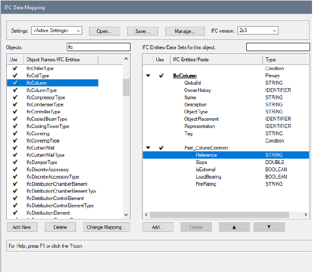
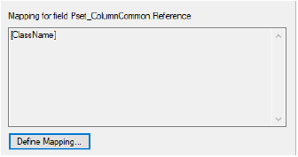
In the IFC Data Mapping dialog box, we add Pset_ColumnCommon and map the Reference field to the class name of the object. We can also add fixed values (TRUE) for IsExternal and LoadBearing.
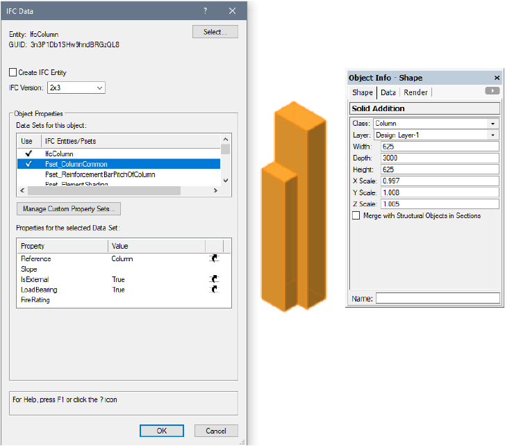
When we select the IFC Data command and select IfcColumn, we can see how our new mapping works:
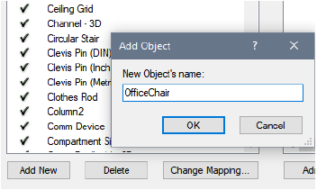
For symbols, besides using mapping for their IFC designation, another option can be used to specify data mapping—using the name of the symbol. We can add the name of the symbol and then define the IFC designation (by clicking Change Mapping) and Psets that we want to be exported (by clicking Add). For example, we add Pset_ManufacturerTypeInformation and then map all the fields to fixed values, since they are the same for all instances of this symbol.
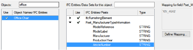
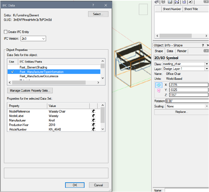
Now, without even attaching IFC data to the symbol definition or to any symbol instances, the symbol is exported as an IfcFurnishingElement with Pset_ManufacturerTypeInformation.We can see the default mapping and the data that will be exported by opening the IFC Data dialog box and clicking OK after verifying the suggested IfcFurnishingElement.
~~~~~~~~~~~~~~~~~~~~~~~~~
 Creating
IFC and COBie Reports
Creating
IFC and COBie ReportsBefore you export an IFC project, create reports to check that drawing objects have appropriate IFC and COBie data associated with them. In the Vectorworks Architect product, use the Create Report command to add the following IFC reports to the drawing (see Using Preformatted Reports).
• Objects with IFC Entity gives a count of IFC objects for each entity type on each layer. The object class, name, and type also display, if available.
• Objects with IFC Entity - Specific lists each IFC object, broken down by entity type (walls, slabs, roofs, doors, windows, stairs, and columns). The object layer, class, name, and description also display, if available.
• Objects without IFC Entity lists non-IFC objects. The object layer, class, type, and type name also display, if available.
Preformatted reports to create standard COBie worksheets are also available. For each COBie worksheet, a companion “help” worksheet is provided, which includes extra columns that display the source for each column of COBie data. These can help you locate and edit data errors.
To edit IFC or COBie data, edit the worksheet directly, and the drawing object will be updated accordingly; see Editing Drawing Objects from a Worksheet.
Certain COBie values are provided automatically by the Vectorworks program, and therefore cannot be edited from a worksheet. In this situation, an alert displays in the Message bar.
You can also create your own worksheets to report and check IFC and COBie data. Set the criteria of the database row to include the desired IFC entities. For each column of the database row, enter a formula to display the desired data.
The Formula bar syntax is similar to that for Displaying Record Information in a Database Column. A record formula has two parts, separated by a period: the record name and the name of the field within the record to display.
Syntax |
Example |
|---|---|
=record_name.field_name |
=Door.Height |
An IFC or COBie formula has three parts instead of two, and there are three types of formulas:
Syntax |
Example |
|---|---|
IFC.entity_name.property_name |
=IFC.IfcDoor.Name |
IFC.pset_name.property_name |
=IFC.Pset_WallCommon.IsExternal |
COBie.worksheet_name.column_name |
=COBie.Component.Description |
To make it easier to enter formulas, an auto-complete feature displays the available entries for each part of a formula as you type. For example, to display an IFC property in a column, first enter =IFC and press the period key. The first name on the list of IFC entities displays. Use the up and down arrow keys to scroll through the list until the desired entity displays. Press the period key again, and the first name on the list of properties for that entity displays. Scroll through the list to display the desired property, and press Enter to complete the formula.

~~~~~~~~~~~~~~~~~~~~~~~~~
 Importing IFC Files
Command |
Path |
|---|---|
Import IFC |
File > Import |
An IFC project, including one that contains multiple buildings or large information sets, can be imported into a Vectorworks file. The units of the imported file are determined by the Vectorworks file. The presentation layers or CAD layers from an imported IFC file are assigned to corresponding Vectorworks classes.
Stories and elements in the IFC file can be filtered during the import, to remove irrelevant objects. Filtering an import can significantly lower the file size, making both the import process and subsequent collaboration more efficient.
To import an IFC file:
1 Select the command.
Alternatively, click the file to import and drag it into an open Vectorworks file.
2 Select the .ifc, .ifczip, or .ifcxml file to open, and click Open.
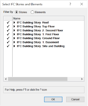
The Select IFC Stories and Elements dialog box opens.
3 All stories and elements are imported by default, but individual stories or ifc elements can be omitted from the import. You can view either stories or elements; choose whether to filter the view by Stories or Elements.
If Stories is selected, a list of all stories in the document displays; a check mark to the left of each story indicates that it is to be imported. To omit one or more whole stories and any associated elements from the import, select the story and click to remove the check mark.
Alternatively, to omit only specific elements on specific stories from the import, click the disclosure arrow to the left of a story name to display the list of IFC elements associated with that story. Select the element(s) to be omitted and click to remove the check mark. The deselected elements are omitted only from that story.
On stories with a combination of selected and deselected elements for import, a dash replaces the check mark.
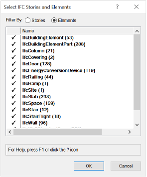
If Elements is selected, a list of all IFC object types in the file displays; the number of elements of each type displays in parentheses to the right of the object type. A check mark to the left of each item in the list indicates that all the elements of that type will be imported. Select the element(s) to be omitted from the import, and click to remove the check mark. The deselected elements are not imported on any story.
If you deselect some items from the elements list, and return to the stories list, stories that contain deselected elements display a dash rather than a check mark, indicating that some elements are not to be imported.
~~~~~~~~~~~~~~~~~~~~~~~~~
 Exporting IFC
Projects
Exporting IFC
ProjectsCommand |
Path |
|---|---|
Export IFC Project |
File > Export |
Vectorworks project files can be exported to .ifc, .ifczip, and .ifcxml formats.
Export to IFC Versions 2x2, 2x3, or 4 is supported. The export of a project to an IFC file is based on specifying the geometry and associated data needed for the use of the exported file. This specification is called a Model View Definition (MVD), which is a subset of all the geometry and data in a building model. MVDs have been created by international, national, or local groups to standardize information exchange for various purposes, such as design coordination, collision/clash detection, structural analysis, and element quantity analysis. You can use MVDs to automate the export, or manually define a custom set of geometry and data to be exported.
You can export a wall with components as a single IFC entity (IfcWall or IfcWallStandardCase), or you can split the wall into the individual components (IfcBuildingElementPart) for estimation purposes. If any component has been modified to have a different height from the rest of the wall, the components are automatically exported as building element parts.
To export a Vectorworks file to IFC:
1 For best results, the following are recommended before export:
• In the Vectorworks Preferences, set the 3D conversion resolution to “Low,” to reduce file size.
• Set the view to Top/Plan.
• Zoom the view into a small, simple corner of the model.
2 Select the command.
The Export IFC Project dialog box opens.
3 Specify the overall project export options, site information, and author data for each pane of the Data tab. Many of the fields are required by the IFC specification; they are automatically mapped to their IFC equivalent for inclusion in the IFC file header information.
► Click to show/hide the parameters.
4 Click the Layer Mapping tab to specify which layers to export, and the Story Name to assign to them at export. If specified, this includes the site model. For a project initially set up with stories, mapping is done automatically so that the layers assigned to the building stories are automatically included in the Mapped Layers list and are mapped to an appropriately named story (Vectorworks Architect required). Mapping can also be controlled manually.
Specify the associated building or site data for each of the mapped layers.
► Click to show/hide the parameters.
5 Either save the export settings, or export the project.
• To save the parameter settings in the Export IFC Project dialog box, without exporting the project, click Save Settings. The parameters and options are saved, and the Export IFC dialog box closes.
• Click Export to export the project.
Indicate the file name and location in the Save As dialog box.
~~~~~~~~~~~~~~~~~~~~~~~~~
 Managing
BCF Information
Managing
BCF InformationCommand |
Path |
|---|---|
Open BCF Manager |
AEC |
The Open BCF Manager command is available for Vectorworks Landmark and Spotlight software but is not present in the those workspaces. It can be added to the Landmark and Spotlight workspaces (see Customizing Workspaces).
BIM Collaboration Format (BCF) allows collaborators to exchange comments between software applications without exchanging the entire BIM model. Issues, proposals, and change requests about a project are “topics” in the BCF file, linked to specific objects in the BIM model. The BCF file only contains comments; it does not modify the model. It can be used to navigate to issues in the model, respond to comments, assign, and resolve issues.
The Vectorworks program allows BCF files to be created, opened, modified, and saved.
There are two typical workflows that take advantage of BCF functionality.
• If exchanging information from a colleague through IFC, import the IFC file into the Vectorworks program, and open the associated .bcfzip file. Navigate to the issues, add or change topics and comments, and save the .bcfzip file to return to your colleague.
• In the Vectorworks program, create or open a model, and export it as an IFC project. Open it in Solibri Model Checker for evaluation and presentation, and save comments, issues, and requests as a .bcfzip file. You or your colleague can then open the model and the .bcfzip file in the Vectorworks program; navigate to the issues, add or change topics and comments, and save the .bcfzip and any changes to the model.
To open or view, edit, and save a BCF file:
1 Open the Vectorworks file that is associated or will become associated with the BCF file.
For best results, the BIM model in the Vectorworks file should exactly match the version of the model that was used when the BCF file was created. An alert displays if this is not the case.
2 If you are creating a new BCF file associated with the Vectorworks file, and there is an issue, comment, or change request that becomes apparent while reviewing the Vectorworks file, select the related object.
3 Select the command.
The BCF Manager dialog box opens.
► Click to show/hide the parameters.
4 After editing or creating BCF topics and comments, save the information by clicking Save and specifying a file name and location for the .bcfzip file.
New topics can be created for the Vectorworks model, and current topics can be edited.
To create or edit BCF topics:
From the BCF manager, click New Topic, or select a topic and click Edit Topic.
The New Topic or Edit Topic dialog box opens.
► Click to show/hide the parameters.
A selected topic can include comments, and a snapshot associated with the comment can be saved and then displayed in the snapshot area.
Comments can only be edited or deleted by the author of the comment.
To add or edit a BCF comment:
1 From the BCF Manager, select a topic from the list of topics.
2 Comments that are already associated with the selected topic display in the Comments on Selected Topic area. Select one for editing and click Edit Comment. Create a new comment associated with the topic by clicking New Comment.
The New Comment or Edit Comment dialog box opens.
► Click to show/hide the parameters.
 :
Mapping is specified for the object, and the object will be
exported to IFC; the mapping displays in the
:
Mapping is specified for the object, and the object will be
exported to IFC; the mapping displays in the  :
Mapping is specified for this object, but the object is excluded
from export by the
:
Mapping is specified for this object, but the object is excluded
from export by the  :
The property set, as defined by its mapping formula, is included
in the IFC export
:
The property set, as defined by its mapping formula, is included
in the IFC export :
The property set is excluded from IFC export
:
The property set is excluded from IFC export
