Elementos EstruturaisElementos Estruturais
The Vectorworks Architect and Spotlight products offer a Structural Member tool for building networks of associated structural members. Structural members can be placed on the working plane, to achieve needed angles, and when they are associated, the ends can be set to align correctly automatically. Structural members can be used as house rigging points when inserting bridles.
Vectorworks Architect software also includes a suite of tools for developing framing plans with additional functionality. There are tools and commands for framing roofs, walls, and floors. Both architects and builders can take advantage of these tools to visualize framing details while still in the design stage of a project, to generate framing detail drawings, and to develop material take-off lists. The Simple Beam Calculator command is also available for analysis of a simply-supported beam with a single load.
Select Tools > Reports > Create Report to add a roof face area worksheet to the drawing. Alternatively, from the Resource Manager, select Vectorworks Libraries\Defaults\Reports_Schedules\Architectural Reports.vwx. Drag the Roof Face Area worksheet to the drawing. The worksheet is populated with information from the objects in the current drawing.
~~~~~~~~~~~~~~~~~~~~~~~~~
 Creating Structural Members
The Structural Member tool has the capability to insert straight and polylinear structural members composed of a variety of common materials and shapes, and to build networks of associated members. Structural members can be aligned with the layer plane or a working plane, as needed.
The following modes are available.

Mode |
Description |
|---|---|
Column Insertion |
Inserts a vertical member |
Linear Insertion |
Inserts a linear member |
Poly Insertion |
Draws a structural member using the selected polyline creation options |
Polyline creation options |
For Poly Insertion mode, selects the method for drawing the polyline upon which the object is based; see Creating Polylines |
Column Height |
For columns with both the Start Bound and End Bound set to Layer Elevation in Structural Member Settings, enter the column height |
Auto Join Members |
When selected, automatically joins connected members and maintains the association between the member being moved and adjoining members; members can be joined to another member’s start or end point, centerline or edge. Associations are maintained for copied and duplicated objects, including objects moved to a different document. |
Preferences |
Opens the Structural Member Settings dialog box to set the default preferences for structural members |


Mode |
Tool |
Workspace: Tool set |
|---|---|---|
Column Insertion |
Structural Member
|
• Architect: Building Shell • Spotlight: Rigging |
To create a vertical structural member:
1 Click the tool and mode, and then click Preferences to set the object defaults (see Structural Member Settings). Most of the properties can be edited later from the Object Info palette.
2 Enter the Column Height on the Tool bar.
3 If Auto Join Members mode is enabled, as you move the cursor over an existing structural member, the object is highlighted, indicating that it can be associated. Click to place the structural member; it is inserted by its base.
Mode |
Tool |
Workspace: Tool set |
|---|---|---|
Linear Insertion |
Structural Member
|
• Architect: Building Shell • Spotlight: Rigging |
To create a linear structural member:
1 Click the tool and mode, and then click Preferences to set the object defaults (see Structural Member Settings). Most of the properties can be edited later from the Object Info palette.
2 If Auto Join Members mode is enabled, as you move the cursor over an existing structural member, the object is highlighted, indicating that it can be associated. Click to place the structural member’s start point, and click again to place the end point.
Mode |
Tool |
Workspace: Tool set |
|---|---|---|
Poly Insertion |
Structural Member
|
• Architect: Building Shell • Spotlight: Rigging |
To create a a structural member by drawing a polyline:
1 Click the tool and mode, and then click Preferences to set the object defaults (see Structural Member Settings). Most of the properties can be edited later from the Object Info palette.
2 If Auto Join Members mode is enabled, as you move the cursor over an existing structural member, the object is highlighted, indicating that it can be associated. Click to set the starting point of the structural member, and then click to set each polyline vertex. Double-click to finish creating the structural member.
For information on using the polyline creation options, see Creating Polylines.
~~~~~~~~~~~~~~~~~~~~~~~~~
 Structural Member
Settings
Structural Member
SettingsStructural member properties can be set in the Structural Member Settings dialog box before the structural member object is inserted in the drawing; access it by clicking the Structural Member tool and then clicking the Preferences button from the Tool bar. These preferences serve as the new default for structural members inserted in the drawing until the preferences are changed.
To set the structural member settings:

1 Click the Profile tab and set the parameters. The Member graphic reflects the Member Type but not the shape.
► Clique para exibir/ocultar parâmetros.
2 Click the Geometry tab and set the parameters. The alignment graphic indicates where the Axis Alignment point is located.
► Clique para exibir/ocultar parâmetros.
3 Click the 2D Attributes tab and set the parameters.
► Clique para exibir/ocultar parâmetros.
4 Click the 3D Attributes tab and set the parameters.
► Clique para exibir/ocultar parâmetros.
~~~~~~~~~~~~~~~~~~~~~~~~~
 Editing
Structural Members
Editing
Structural MembersEdit the path of selected structural members by using the Reshape tool, or right-click on the member and select Edit from the context menu. See Remodelando Objetos for information on using the Reshape tool for editing. Use the Rotate Tool to rotate the path of the object. Associations among structural members can be affected by the use of these tools.
Many, but not all, parameters can be edited for selected structural member objects after placement, in the Object Info palette. To edit parameters that are not in the Object Info palette, click Settings to open the Structural Member Settings dialog box.
You can enable the option to Use Layer Cut Plane Elevation. When selected, and the design layer cut plane is enabled, the elevation of the structural member cut plane is set to the same value as that of the design layer, ensuring a uniform cut plane appearance for the layer.
When the design layer cut plane is disabled, specify a Cut Plane Elevation for the structural member.
Structural members that are associated using Auto Join Members mode move and change length as necessary to maintain the association. However, if the structural member is moved so that associations are no longer reasonable, the association is broken, and the start or end conditions of the member change to custom.
~~~~~~~~~~~~~~~~~~~~~~~~~
 Framing a
Roof
Framing a
RoofCommand |
Path |
|---|---|
Roof Framer |
AEC > Framing |
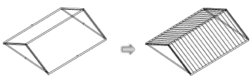
A roof object can be automatically framed with rafters, collars (collar beams), ridges, and other roof elements with the Roof Framer command. The command creates framing member objects. If Enable Auto-classing is selected in the Standard Naming dialog box, all roof framing members will be automatically placed in the Structural-Framing class.
This command does not work on roof face objects.
To automatically frame a roof:
1 Select the roof object.
2 Select the command.
The Roof Framer dialog box opens.
3 Select the tab for the type of roof framing element to create, and select the check box to create the framing element. More than one type can be selected at the same time; other framing elements can be added later.
An individual framing element can be added with the Framing Member tool, available from the Detailing tool set.
4 Enter the framing parameters for each desired framing element as described in the following sections.
5 Instead of aligning the framing to the top or bottom of the roof, the framing can be aligned to a roof component when components have been defined or when they are included as part of a roof style. Select Use Roof Components and then select the component for alignment from the Select Roof Component list.
6 For each selected roof framing element, click Object Attributes to specify its appearance.
The Attributes dialog box opens. See Applying Object Attributes for information on applying graphic attributes, and Applying and Mapping Textures for information on texture parameters.
► Clique para exibir/ocultar parâmetros.
~~~~~~~~~~~~~~~~~~~~~~~~~
 Creating Rafters
Command |
Path |
|---|---|
Roof Framer |
AEC > Framing |
To create rafters:
1 Select the roof object.
2 Select the command.
The Roof Framer dialog box opens.
3 Click the Rafters tab, and select Create Rafters.
4 Specify the rafter parameters.
► Clique para exibir/ocultar parâmetros.

~~~~~~~~~~~~~~~~~~~~~~~~~
 Creating Collars
Command |
Path |
|---|---|
Roof Framer |
AEC > Framing |
To create collars (collar beams):
1 Select the roof object.
2 Select the command.
The Roof Framer dialog box opens.
3 Click the Collars tab, and select Create Collars.
4 Specify the collar parameters.
► Clique para exibir/ocultar parâmetros.

~~~~~~~~~~~~~~~~~~~~~~~~~
 Creating Plates
Command |
Path |
|---|---|
Roof Framer |
AEC > Framing |
To create plates
1 Select the roof object.
2 Select the command.
The Roof Framer dialog box opens.
3 Click the Plates tab, and select Create Plates.
4 Specify the plate parameters.
► Clique para exibir/ocultar parâmetros.

~~~~~~~~~~~~~~~~~~~~~~~~~
 Creating Purlins
Command |
Path |
|---|---|
Roof Framer |
AEC > Framing |
To create purlins:
1 Select the roof object.
2 Select the command.
The Roof Framer dialog box opens.
3 Click the Purlins tab, and select Create Purlins.
4 Specify the purlin parameters.
► Clique para exibir/ocultar parâmetros.

~~~~~~~~~~~~~~~~~~~~~~~~~
 Creating Ridges
Command |
Path |
|---|---|
Roof Framer |
AEC > Framing |
To create ridges:
1 Select the roof object.
2 Select the command.
The Roof Framer dialog box opens.
3 Click the Ridges tab, and select Create Ridges.
4 Specify the ridge parameters.
► Clique para exibir/ocultar parâmetros.

~~~~~~~~~~~~~~~~~~~~~~~~~
 Creating Headers
Command |
Path |
|---|---|
Roof Framer |
AEC > Framing |
To create headers:
1 Select the roof object.
2 Select the command.
The Roof Framer dialog box opens.
3 Click the Headers tab, and select Create Headers.
4 Specify the header parameters.
► Clique para exibir/ocultar parâmetros.

~~~~~~~~~~~~~~~~~~~~~~~~~
 Creating
Hip and Valley Rafters
Creating
Hip and Valley RaftersCommand |
Path |
|---|---|
Roof Framer |
AEC > Framing |
To create hip and valley rafters:
1 Select the roof object.
2 Select the command.
The Roof Framer dialog box opens.
3 Click the Hips/Valleys tab, and select Create Hips and Valleys.
4 Specify the hip and valley rafter parameters.
► Clique para exibir/ocultar parâmetros.

~~~~~~~~~~~~~~~~~~~~~~~~~
 Custom
Frame Element Sizes
Custom
Frame Element SizesThe size of the framing elements can be selected from a pre-set list, or the list can be edited to contain desired or custom sizes.
To edit the size list of the frame elements:
From the Size field in one of the framing element tabs of the Roof Framer dialog box, select Edit List. The Edit Size List dialog box opens, listing the currently available sizes of the roof element.
► Clique para exibir/ocultar parâmetros.
The text files that populate the size lists in the framing element dialog boxes can also be edited. The text files are located in the Vectorworks application folder [Vectorworks]\Plug-Ins\VW_Arch\Data.
~~~~~~~~~~~~~~~~~~~~~~~~~
 Creating
Framing Members
Creating
Framing MembersMode |
Tool |
Tool set |
|---|---|---|
Modes for Creating Lines |
Framing Member
|
Detailing |
The Framing Member tool draws framing elements for rafters, beams, joists, and framing members with a horizontal projection.
For a file created in a version of Vectorworks Architect prior to 2009, board, joist, rafter, and original framing member objects are considered to be “legacy” objects. To convert them to the current functionality of the framing member tool, select Tools > Utilities > Update Plug-in Objects; see Migrando de Versões Anteriores.
To create a framing member:
1 Click the tool and mode.
2 Click to place the object in the drawing, and click again to set the length and rotation. The first time you use the tool in a file, a properties dialog box opens. Set the default properties. The properties can be edited from the Object Info palette.
The starting point and direction in which the framing member is drawn determine which end is which. When a single framing member object is selected in Top/Plan view, a blue arrow is placed at the starting point and indicates the object’s direction.

► Clique para exibir/ocultar parâmetros.
~~~~~~~~~~~~~~~~~~~~~~~~~
 Framing
a Floor
Framing
a FloorCommand |
Workspace: Path |
|---|---|
Create Joists |
• Architect: AEC > Framing • Landmark: Landmark > Architectural |
Use the Create Joists command to create the joist and perimeter objects necessary to frame a floor. If the floor is a slab object, select the slab component to serve as a boundary for the joist area. The command creates framing member objects.
To frame a floor:
1 Select a rectangle, polygon, polyline, extrude, roof face, slab, or floor object.
If a stairwell hole exists in the floor, solid beam framing member objects are used for the headers.
2 Select the command.
The Create Joists dialog box opens.
► Clique para exibir/ocultar parâmetros.
3 Select whether to draw joists and/or perimeter framing members for the floor framing. Then, specify the properties of the joists and the perimeter framing. Click Set Joist Properties or click Set Framing Member Properties.
The Set Joist Properties or Set Framing Member Properties dialog box opens. The available parameters depend on the Type of joist or framing member selected.
► Clique para exibir/ocultar parâmetros.
4 Click OK to set the joist or perimeter framing member properties.
5 Specify the attributes of the joists and the perimeter framing. Click Set Joist Attributes or click Set Framing Member Attributes.
The Set Joist Attributes or Set Framing Member Attributes dialog box opens. The dialog boxes are identical whether setting joist or perimeter framing attributes, and contain a Graphic Attributes tab and Texture tab.
► Clique para exibir/ocultar parâmetros.
6 If joists are to be created, click two points to indicate the desired joist orientation.
7 The joists and/or perimeter framing member objects are created. In addition, a Joist Take-Off worksheet is automatically created and displays in the Resource Manager.
The framing member parameters can be edited from the Object Info palette. These parameters are identical to those of a single framing member object.
~~~~~~~~~~~~~~~~~~~~~~~~~
 Framing a Wall
Command |
Path |
|---|---|
Wall Framer |
AEC > Framing |
The Vectorworks Architect product creates a highly detailed estimate of the placement and number of studs needed to frame walls. In addition to showing stud placement in a framing diagram, the Wall Framer command also automatically generates frame elevation drawings and two different worksheets, Frame TakeOff and Frame Wall Info.
To use the wall framer:
1 Ensure that the walls have the desired height. If necessary, change the wall height.
2 Select the command.
If a framing model has not yet been created, the New Framing Model dialog box opens. Enter a name for the framing model design layer (up to eight characters).
3 Click Create.
The Wall Framing dialog box opens. Select the desired settings for the framing model.
► Clique para exibir/ocultar parâmetros.
The framing diagram and the 3D model representations also include symbols and inserted items, such as doors and windows.
The Wall Class dialog box opens. Enter the framing parameters for each wall class.
► Clique para exibir/ocultar parâmetros.
The program creates the estimated framing for the walls and any other output information requested.
The 2D results display in Top/Plan view without a top plate. To view the results with a top plate, switch to another view such as Front, Back, Left, or Right.
To view the 3D results, switch to a view such as Left Isometric or Right Isometric.
The Framer TakeOff and Framer Wall Info worksheets, if created, display in the drawing area.
~~~~~~~~~~~~~~~~~~~~~~~~~
 Inserting
Ceiling Grid Objects
Inserting
Ceiling Grid ObjectsTool |
Tool set |
|---|---|
Ceiling Grid
|
• Furn/Fixtures • MEP |
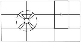
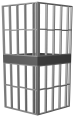
Use the Ceiling Grid tool to insert a ceiling grid object containing tiles with user-specified length, width, and placement angle. A ceiling grid object can also be created by drawing a polyline and then selecting the Create Objects from Shapes command (see Creating Objects from Shapes).
To insert a ceiling grid object:
1 Click the tool.
2 Click in the drawing file to set the start point of the ceiling grid object, and then click to set the position of each additional vertex. Click the last point to complete creation of the ceiling grid object. If the polyline is open, the program automatically completes it.
The first time you use the tool in a file, a properties dialog box opens. Set the default properties. The properties can be edited from the Object Info palette.
3 Use the Reshape tool to modify the locations of the vertices after object creation, or use the vertex editing controls from the Object Info palette to move the vertices or change the degree of vertices. The tiles are automatically adjusted to fit the new shape.
► Clique para exibir/ocultar parâmetros.
For information on editing object vertices, see Remodelando Objetos.
 Creating
Linear Material Details
Creating
Linear Material DetailsMode |
Tool |
Tool set |
|---|---|---|
Modes for the Polyline Tool |
Linear Material
|
Detailing |
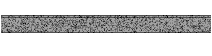
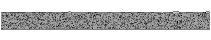
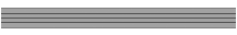
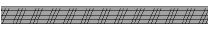
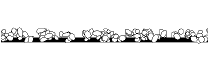
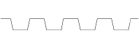
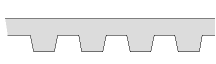
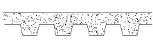
The Linear Material tool draws a standard representation of sheet building materials (such as plywood, gypsum board, and stucco) along a path. To create linear material details, either use the Linear Material tool, or draw a polyline and then select the Create Objects from Shapes command (see Creating Objects from Shapes).
To draw linear material details:
1 Click the tool and mode, and if desired set the linear material attributes from the Attributes palette (fill style, pen style, and line thickness). The linear material attributes can also be specified after creation.
2 Click to set the object’s start point.
3 Click to set the end of the segment and the beginning of the next. Continue drawing segments in this manner until the object is complete.
4 Click a second time at the start point to complete a closed polyline object, or double-click to complete an open polyline object.
The linear material parameters can be edited from the Object Info palette.
► Clique para exibir/ocultar parâmetros.
Linear material details with stipple patterns may require a significant amount of time to draw.
Create a plug-in symbol from a linear material object (see Criando Definições de Símbolos) with Convert to Plug-in Object selected. Activate the symbol in the Resource Manager to draw the linear material detail with the saved symbol parameters.
Several commonly used structural steel shapes are available as 2D objects. 3D equivalents of these objects are also available in the Vectorworks Design Series products. Since the 2D and 3D parameters are nearly identical, all parameters are documented with the 2D objects for convenience. Two additional 2D/3D structural shapes are also available in the Vectorworks Design Series products: bulb flat and Z-section, as well as four additional series (ANZ, BSI, DIN, and JIS).
The Update Plug-in Objects command may need to be run on files containing structural shapes that were created in an earlier version of the software. This command converts the structural shapes to the latest format; see Migrando de Versões Anteriores.
~~~~~~~~~~~~~~~~~~~~~~~~~
Mode |
Tool |
Tool set |
|---|---|---|
Modes for The Symbol Insertion Tool |
|
Detailing |
The Angle tool and Angle - 3D tool share the same position on the tool set. Click and hold the mouse on the visible tool to open the Ferramentas Pop-out list and select the desired tool.

To create an angle:
1 Click the tool and mode.
2 Click to place the object in the drawing, and click again to set the rotation. The first time you use the tool in a file, a properties dialog box opens. Set the default properties. The properties can be edited from the Object Info palette.
► Clique para exibir/ocultar parâmetros.
~~~~~~~~~~~~~~~~~~~~~~~~~
Mode |
Tool |
Tool set |
|---|---|---|
Modes for The Symbol Insertion Tool |
|
Detailing |
The Channel tool and Channel - 3D tool share the same position on the tool set. Click and hold the mouse on the visible tool to open the Ferramentas Pop-out list and select the desired tool.

To create a channel:
1 Click the tool and mode.
2 Click to place the object in the drawing, and click again to set the rotation. The first time you use the tool in a file, a properties dialog box opens. Set the default properties. The properties can be edited from the Object Info palette.
► Clique para exibir/ocultar parâmetros.
~~~~~~~~~~~~~~~~~~~~~~~~~
Mode |
Tool |
Tool set |
|---|---|---|
Modes for The Symbol Insertion Tool |
|
Detailing |
The I-Beam tool and I-Beam - 3D tool share the same position on the tool set. Click and hold the mouse on the visible tool to open the Ferramentas Pop-out list and select the desired tool.

To create an I-beam:
1 Click the tool and mode.
2 Click to place the object in the drawing, and click again to set the rotation. The first time you use the tool in a file, a properties dialog box opens. Set the default properties. The properties can be edited from the Object Info palette.
► Clique para exibir/ocultar parâmetros.
~~~~~~~~~~~~~~~~~~~~~~~~~
Mode |
Tool |
Tool set |
|---|---|---|
Modes for The Symbol Insertion Tool |
Rectangular Tubing
|
Detailing |
The Rectangular Tubing tool and Rectangular Tubing - 3D tool share the same position on the tool set. Click and hold the mouse on the visible tool to open the Ferramentas Pop-out list and select the desired tool.

To create rectangular tubing:
1 Click the tool and mode.
2 Click to place the object in the drawing, and click again to set the rotation. The first time you use the tool in a file, a properties dialog box opens. Set the default properties. The properties can be edited from the Object Info palette.
► Clique para exibir/ocultar parâmetros.
~~~~~~~~~~~~~~~~~~~~~~~~~
Mode |
Tool |
Tool set |
|---|---|---|
Modes for The Symbol Insertion Tool |
Round Tubing
|
Detailing |
The Round Tubing tool and Round Tubing - 3D tool share the same position on the tool set. Click and hold the mouse on the visible tool to open the Ferramentas Pop-out list and select the desired tool.

To create round tubing:
1 Click the tool and mode.
2 Click to place the object in the drawing, and click again to set the rotation. The first time you use the tool in a file, a properties dialog box opens. Set the default properties. The properties can be edited from the Object Info palette.
► Clique para exibir/ocultar parâmetros.
~~~~~~~~~~~~~~~~~~~~~~~~~
Mode |
Tool |
Tool set |
|---|---|---|
Modes for The Symbol Insertion Tool |
Square Tubing
|
Detailing |
The Square Tubing tool and Square Tubing - 3D tool share the same position on the tool set. Click and hold the mouse on the visible tool to open the Ferramentas Pop-out list and select the desired tool.

To create square tubing:
1 Click the tool and mode.
2 Click to place the object in the drawing, and click again to set the rotation. The first time you use the tool in a file, a properties dialog box opens. Set the default properties. The properties can be edited from the Object Info palette.
► Clique para exibir/ocultar parâmetros.
~~~~~~~~~~~~~~~~~~~~~~~~~
Mode |
Tool |
Tool set |
|---|---|---|
Modes for The Symbol Insertion Tool |
|
Detailing |
The Tee tool and Tee - 3D tool share the same position on the tool set. Click and hold the mouse on the visible tool to open the Ferramentas Pop-out list and select the desired tool.

To create a tee:
1 Click the tool and mode.
2 Click to place the object in the drawing, and click again to set the rotation. The first time you use the tool in a file, a properties dialog box opens. Set the default properties. The properties can be edited from the Object Info palette.
► Clique para exibir/ocultar parâmetros.
~~~~~~~~~~~~~~~~~~~~~~~~~
Mode |
Tool |
Tool set |
|---|---|---|
Modes for The Symbol Insertion Tool |
Wide Flange
|
Detailing |
The Wide Flange tool and Wide Flange - 3D tool share the same position on the tool set. Click and hold the mouse on the visible tool to open the Ferramentas Pop-out list and select the desired tool.

To create a wide flange:
1 Click the tool and mode.
2 Click to place the object in the drawing, and click again to set the rotation. The first time you use the tool in a file, a properties dialog box opens. Set the default properties. The properties can be edited from the Object Info palette.
► Clique para exibir/ocultar parâmetros.
~~~~~~~~~~~~~~~~~~~~~~~~~
Tool |
Tool set |
|---|---|
Shaft Break
|
Detailing |
To insert a shaft break:
1 Click the tool and mode.
2 Click to place the object in the drawing, and click again to set the rotation. The first time you use the tool in a file, a properties dialog box opens. Set the default properties. The properties can be edited from the Object Info palette.

► Clique para exibir/ocultar parâmetros.
~~~~~~~~~~~~~~~~~~~~~~~~~
 Shaft
Break 2
Shaft
Break 2Tool |
Tool set |
|---|---|
Shaft Break 2
|
Detailing |
To insert a shaft break 2 object.
1 Click the tool and mode.
2 Click to place the object in the drawing, and click again to set the rotation. The first time you use the tool in a file, a properties dialog box opens. Set the default properties. The properties can be edited from the Object Info palette.

► Clique para exibir/ocultar parâmetros.
~~~~~~~~~~~~~~~~~~~~~~~~~
Tool |
Tool set |
|---|---|
|
|
Detailing |
To insert a slot:
1 Click the tool and mode.
2 Click to define the start point of the slot, click again to define the end point and rotation, and drag the cursor and click to set the slot width.
► Clique para exibir/ocultar parâmetros.
~~~~~~~~~~~~~~~~~~~~~~~~~
Mode |
Tool |
Tool set |
|---|---|---|
Modes for Creating Lines |
Batt Insulation
|
Detailing |
The Batt Insulation tool draws a planar insulation fill along a line. This tool is useful for creating custom details. The insulation can be placed within a wall, where it automatically adjusts to the length of the wall.
A better method of creating insulation fills, especially for walls, is to use a tile fill, which scales and rotates within walls and slab and wall components.
To create batt insulation:
1 Click the tool and mode.
2 Click to place the object in the drawing, and click again to set the length and rotation. The first time you use the tool in a file, a properties dialog box opens. Set the default properties. The properties can be edited from the Object Info palette.
3 The created batt insulation can be dragged into an existing wall.

► Clique para exibir/ocultar parâmetros.
~~~~~~~~~~~~~~~~~~~~~~~~~
 Bulb Flat
Mode |
Tool |
Tool set |
|---|---|---|
Modes for The Symbol Insertion Tool |
Bulb Flat
|
Detailing |
The Bulb Flat tool and Bulb Flat - 3D tool share the same position on the tool set. Click and hold the mouse on the visible tool to open the Ferramentas Pop-out list and select the desired tool.

To create a bulb flat object:
1 Click the tool and mode.
2 Click to place the object in the drawing, and click again to set the rotation. The first time you use the tool in a file, a properties dialog box opens. Set the default properties. The properties can be edited from the Object Info palette.
► Clique para exibir/ocultar parâmetros.
~~~~~~~~~~~~~~~~~~~~~~~~~
 Z-Section
Mode |
Tool |
Tool set |
|---|---|---|
Modes for The Symbol Insertion Tool |
|
Detailing |
The Z-Section tool and Z-Section - 3D tool share the same position on the tool set. Click and hold the mouse on the visible tool to open the Ferramentas Pop-out list and select the desired tool.

To create a Z-section object:
1 Click the tool and mode.
2 Click to place the object in the drawing, and click again to set the rotation. The first time you use the tool in a file, a properties dialog box opens. Set the default properties. The properties can be edited from the Object Info palette.
► Clique para exibir/ocultar parâmetros.
~~~~~~~~~~~~~~~~~~~~~~~~~