 Editando
ParedesEditando
Paredes
Editando
ParedesEditando
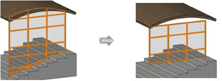
ParedesEdit the properties of selected straight or round walls and their components, as well as curtain walls, from the Object Info palette. To change the wall attributes, use the Attributes palette. Certain parameters are available for standard walls or for curtain walls only. Settings on the Render tab are not available for curtain walls, since the textures of frames and panels are specified separately. Use the Edit Curtain Wall tool to adjust the frames and panels of curtain walls.
► Clique para exibir/ocultar parâmetros.
 Wall Display with Design Layer
Cut Plane Enabled
Wall Display with Design Layer
Cut Plane EnabledThe Vectorworks Architect product allows a cut plane elevation to be set and enabled for the design layer; see Definindo Propriedades da Camada de Projeto. The layer cut plane applies to several drawing objects, including standard walls, curtain walls, wall features, and objects inserted into the wall.
When the design layer cut plane is enabled, the following rules apply:
• Walls are drawn only to the extents intersected by the layer cut plane. The contour at the cut plane is drawn as an outline only, using the Pen attribute, emphasizing the cut plane while still allowing the components to be seen.
• Low walls (with tops below the cut plane) and wall features below the cut plane are drawn with the Below Attributes Class selected from the Attributes Below Cut Plane list in the Wall Attributes dialog box, or by the extents attributes set for below the cut plane for wall features.
• Walls seen from above are always drawn with caps and do not show the divisions between components.
• Wall breaks (joins) are drawn only when both walls in the join area intersect the cut plane.
• Windows and doors inserted into a wall are drawn normally when they are at the cut plane elevation, and with a simplified, non-breaking appearance when they do not intersect the cut plane elevation. Windows can have a different “clerestory” appearance when the Clerestory option is enabled in the Window Settings: 3D Visualization Pane.
• Objects inserted into the wall that are at the cut plane are shown drawn in the wall. Objects that are inserted below the cut plane, but that do not intersect the cut plane, are drawn with dashed lines.
~~~~~~~~~~~~~~~~~~~~~~~~~
Use the Reshape tool in a 3D view to edit the wall height, change the elevation of wall peaks, add vertices to create peaks in an existing wall, and delete vertices that have been added. Wall peaks can also be removed with the Delete Wall Peaks command (Vectorworks Architect or Landmark required). Use the Selection tool to change the wall length. Symbols remain where placed when a wall is reshaped.
Although a Design Series product is required to create walls, existing walls can be changed using some tools available with a Fundamentals license.
In the following situations, the Reshape tool displays 2D Reshape modes; the vertices at either end of the wall can be moved, to change the wall length and/or location. See Modos de Remodelagem 2D.
• In Top/Plan view
• When multiple walls are selected
• When a wall and other objects are selected
• When a marquee has been drawn
In any 3D view, when only a single wall is selected, the Reshape tool has three modes available.

Mode |
Description |
|---|---|
Reshape 3D Walls |
Adjusts the position of a selected wall vertex |
Add 3D Wall Peaks |
Adds a vertex to a wall for reshaping purposes |
Delete 3D Wall Peaks |
Deletes a wall vertex |
Walls can also be trimmed with the Ferramenta Aparar.
~~~~~~~~~~~~~~~~~~~~~~~~~
Mode |
Tool |
Tool set |
|---|---|---|
Single Object Interactive Scaling
|
Selection
|
Basic |
Although a Design Series product is required to create walls, existing walls can be changed using some tools available with a Fundamentals license.
To change a wall’s length:
1 Click the tool and mode.
2 Select the wall to reshape.
3 Click and drag a selection handle to lengthen or shorten the wall.
4 Click again when the wall is at the desired length.

In Top/Plan view, you can also change wall length with the Reshape tool. In a 3D view, draw a marquee with the Reshape tool to enclose the wall vertex in a marquee that is co-planar with the bottom wall elevation. Select the wall with the Reshape tool. The available modes switch to the 2D reshape modes, and 2D reshape functionality is enabled (see Modos de Remodelagem 2D).
~~~~~~~~~~~~~~~~~~~~~~~~~
Mode |
Tool |
Tool set |
|---|---|---|
Reshape 3D Walls
|
Reshape
|
Basic |
Although a Design Series product is required to create walls, existing walls can be changed using some tools available with a Fundamentals license.
To change the height of the wall:
1 In a 3D view, select the wall to reshape.
2 Click the tool and mode.
3 Click and drag one of the reshape handles.
• Click a middle handle to change the height of the entire wall.
• Click an end handle to change the height of one end only.


~~~~~~~~~~~~~~~~~~~~~~~~~
Mode |
Tool |
Tool set |
|---|---|---|
Add 3D Wall Peaks
|
Reshape
|
Basic |
Although a Design Series product is required to create walls, existing walls can be changed using some tools available with a Fundamentals license.
To add a wall peak:
1 In a 3D view, select the wall that requires a peak (vertex).
2 Click the tool and mode.
3 Click a corner handle or an existing vertex, and move the cursor to the location of the vertex to be added.
4 Click to place the vertex.

Use the Fit Walls to Objects command to automatically fit walls to selected geometry (Vectorworks Architect or Landmark required).
To reshape a curved wall to match a planar surface, use the Subtract Solids or Intersect Solids command with an object that matches the plane of the roof.
~~~~~~~~~~~~~~~~~~~~~~~~~
 Deleting All Wall Peaks
Command |
Workspace: Path |
|---|---|
Delete Wall Peaks |
• Architect: AEC • Landmark: Architectural |
To remove wall peaks:
1 Select the wall.
2 Select the command.
The Delete Wall Peaks dialog box opens.
3 Select whether to remove the peaks from the top of the wall, the bottom of the wall, or both.
For unstyled walls, the top and/or bottom of the wall is set to the specified top or bottom boundary (normally, this is the layer elevation). Top or bottom offsets reset to 0 automatically; to prevent a situation where the wall has a height of 0, an offset is added if necessary.
For styled walls, the wall reverts to the top and/or bottom boundary set by the wall style.
Mode |
Tool |
Tool set |
|---|---|---|
Delete 3D Wall Peaks
|
Reshape
|
Basic |
Although a Design Series product is required to create walls, existing walls can be changed using some tools available with a Fundamentals license.
To remove individual wall peaks:
1 In a 3D view, select the wall with the peak (vertex) to be deleted.
2 Click the tool and mode.
3 Click the vertex to delete.
The vertex is removed and the wall is reshaped to the remaining vertices.

~~~~~~~~~~~~~~~~~~~~~~~~~
Tool |
Tool set |
|---|---|
Selection
|
Basic |
Although a Design Series product is required to create walls, existing walls can be changed using some tools available with a Fundamentals license.
To change the radius of a round wall:
1 Select the round wall.
2 Click and drag the center control point to increase or decrease the radius of the wall.
3 Click again when the wall is at the desired size.

Flip the round wall arc by dragging toward, and through, the arc center.
~~~~~~~~~~~~~~~~~~~~~~~~~
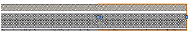
 Removing Wall Breaks
Tool |
Tool set |
|---|---|
Remove Wall Breaks
|
Building Shell |
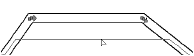
The Remove Wall Breaks tool cleans up any wall breaks or gaps that were created during editing. For example, if you create a new wall that joins an existing wall, and then later delete the new wall, a break in the remaining wall displays at the joint. The Remove Wall Breaks tool removes the break and any end caps.
To remove wall breaks:
1 Click the tool.
Alternatively, right-click on the wall and select Remove Break from the context menu.
2 Click and drag to create a marquee box around the wall break or end cap to remove.
The wall break or end cap is automatically removed.
![]()
~~~~~~~~~~~~~~~~~~~~~~~~~
 Moving
Connected Walls
Moving
Connected WallsMode |
Tool |
Tool set |
|---|---|---|
Connected Walls
|
Selection
|
Basic |
The Selection tool’s Connected Walls mode automatically maintains the connection between the wall being moved and adjoining walls. The involved wall angles remain constrained throughout the move. While dragging a wall, you can enter precise offset distances in the Offset field of the Tool bar.
The Connected Walls mode does not apply to Y-joined walls or round walls.
Connections between T-joined walls and L-joined walls are also maintained if they are moved using the Move or Nudge command, or moved and/or duplicated using the Duplicate Array command or the Move by Points tool, as long as the ends of the moved or duplicated walls overlap with the walls to which they were originally connected.

To move a wall while maintaining its connection to adjacent walls:
1 Click the tool and mode.
2 Click the desired wall and drag it to a new location; alternatively, change the wall length by editing the L value from the Object Info palette (polar coordinates), or by editing a dimension value. The walls stay connected during the move.
When you move a wall connected between two other walls, the wall being moved is resized to maintain the connection. Moving a T- or L-joined wall beyond the end of the connected wall disconnects the walls.
End-to-end walls joined as an L-join move together as a single wall.
For corner joined walls, all involved walls are resized to maintain the connection. A wall cannot be moved in such a way that its length equals zero.
To move a collection of walls without changing the walls relative to each other, deselect the Connected Walls mode, and then move the walls.
~~~~~~~~~~~~~~~~~~~~~~~~~
Command |
Path |
|---|---|
Vectorworks Preferences |
Tools > Options |
The Vectorworks preference Auto join walls automatically joins walls at corners and intersections, and automatically heals the mitered ends of walls when they are separated from one another. For T joins, the break in the side of the wall is healed. Walls can be in either 2D or 3D view.

When a core component has been set for walls with components, the components also automatically join. Core components, as well as the other components, join capped if they do not have the same fill. The status of the wall component setting Always Auto Join in Capped Join Mode determines whether components that have the same fill are joined with a capped or mitered configuration (see Defining Components for New Walls).
To set the preference:
1 Select the command.
2 On the Edit tab, select Auto join walls.
 Automatically
Joining Walls in Rectangle Mode
Automatically
Joining Walls in Rectangle ModeWhen the Vectorworks preference Auto join walls is on, walls drawn in Rectangle mode that are parallel and overlap or touch each other interact. The drawing operation can be performed using the default Add option, which combines interacting walls, or using the Subtract option, which deletes interacting wall segments. A set of rules determines these interactions.
The existing walls that interact with the new walls are highlighted while drawing.
The existing overlapped wall remains, and the new overlapping wall is not created.

If the new wall extends the existing wall and has the same style, the existing wall is extended and the new wall is not created. If the new wall has a different style, it is created.


Press and hold Alt (Windows) or Option (Mac) while drawing to delete the overlapped portion of the existing wall; the new overlapping wall is not created.

If the new wall extends the existing wall and has the same style, the existing wall is extended and the new wall is not created.

If the new wall partially extends and partially overlaps an existing wall, the overlapping portion is deleted and the extending portion is created with the new wall.

When a wall subtraction requires that the existing walls change direction to maintain the correct orientation, the wall direction changes automatically (see Wall Direction).

~~~~~~~~~~~~~~~~~~~~~~~~~
 Joining Walls
The Wall Join tool is in t the Building Shell tool set (all Design Series workspaces), and the Site Planning tool set (Landmark workspace).
The Wall Join tool joins straight or curved wall segments and their components. There are three modes for joining walls and two end cap modes.

Mode |
Description |
|---|---|
T Join |
Lengthens or shortens one wall segment until it intersects with the second wall segment selected; creates Y joins by joining the first selected wall to two sections of an existing L join |
L Join |
Joins the closest ends of two walls to create a corner |
X Join |
Joins two wall segments at the point where they intersect |
Uncapped Join |
Applies an uncapped join to wall join operations |
Capped Join |
Applies a capped join to wall join operations |
To temporarily activate this tool, right-click on a wall, and select Join from the context menu. The tool defaults to the mode used previously with the tool.
|
Click here for a video tip about this topic (internet access required). |
~~~~~~~~~~~~~~~~~~~~~~~~~
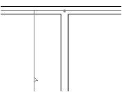
 T Wall Joins
Mode |
Tool |
Tool set |
|---|---|---|
T Join
|
Wall Join
|
• Architect and Spotlight: Building Shell • Landmark: Building Shell and Site Planning |
T Join mode lengthens or shortens the first wall segment selected until it intersects with the second wall segment selected. As only the first wall is altered, this mode does not create corner joins.
To join walls with the T Join mode:
1 Click the tool and mode.
Alternatively, right-click on the first wall to join and select Join from the context menu.
2 Select the wall segment that must change length to intersect with the other wall.
3 Select the second wall segment to join.

To create a T join to an existing corner, join the wall segment to the perpendicular corner segment. This creates a clean join between the walls.

~~~~~~~~~~~~~~~~~~~~~~~~~
 Y Wall Joins
Mode |
Tool |
Tool set |
|---|---|---|
T Join
|
Wall Join
|
• Architect and Spotlight: Building Shell • Landmark: Building Shell and Site Planning |
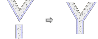
Y wall joins are not automatically created when you use the Auto join walls preference. (See Aba Edição for information on Auto join walls.) Instead, use the T Join mode to create Y wall joins.
To create a Y wall join of three wall segments:
1 Click the tool and mode.
Alternatively, right-click on the first wall to join and select Join from the context menu.
2 Select the wall segment that must change length to abut the two previously joined wall segments.
3 Select one of the two wall segments to join.
The wall segments are joined.

~~~~~~~~~~~~~~~~~~~~~~~~~
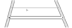
 L Wall Joins
Mode |
Tool |
Tool set |
|---|---|---|
L Join |
Wall Join
|
• Architect and Spotlight: Building Shell • Landmark: Building Shell and Site Planning |
L Join mode joins the closest ends of two walls to create a corner, or joins two walls end to end. Both wall lengths are automatically resized as necessary to meet cleanly.
To join walls with the L Join mode:
1 Click the tool and mode.
Alternatively, right-click on the first wall to join and select Join from the context menu.
2 Select the first wall segment to join.
3 Select the second wall segment to join. For corner joins, the location of the clicks defines the direction of the L.
The wall lengths are automatically resized and joined.

~~~~~~~~~~~~~~~~~~~~~~~~~
 X Wall Joins
Mode |
Tool |
Tool set |
|---|---|---|
X Join
|
Wall Join
|
• Architect and Spotlight: Building Shell • Landmark: Building Shell and Site Planning |
X Join mode joins two wall segments at the point where they intersect. Because neither wall segment’s length is altered, the two segments must already intersect in order to use this mode.
To join walls with the X Join mode:
1 Click the tool and mode.
Alternatively, right-click on the first wall to join and select Join from the context menu.
2 Select the wall segment to become non-load bearing.
3 Select the wall segment to become load bearing.

The first wall segment selected is split into two wall segments, which are joined to the load bearing wall.
~~~~~~~~~~~~~~~~~~~~~~~~~
 Joining
Walls with the Fillet Tool
Joining
Walls with the Fillet ToolThe Fillet tool, located on the Basic palette, joins two wall segments by creating a round wall between them. See Criando Filetes e Chanfros.

~~~~~~~~~~~~~~~~~~~~~~~~~
 Joining Wall Components
The Component Join tool is in the Building Shell tool set.
The Component Join tool joins the selected components between two straight wall segments; components within pre-existing joined wall segments can also be joined. There are three modes for joining wall components.

Mode |
Description |
|---|---|
T Join |
Extends or shortens one wall component segment until it intersects with a second wall component segment |
L Join |
Joins the closest ends of two wall components to create a corner |
Capped Join |
Applies a capped join to the component being joined |
Components can be joined to the edge of walls instead of specific components in Capped Join mode.
Normally, when you join walls with the Wall Join tool, and the Auto join walls preference is enabled, the components automatically join correctly. A core component must be set. (See Joining Walls.)
The Component Join tool is useful for adjusting components that did not join as desired when walls were connected, even in complex wall joins.
|
Click here for a video tip about this topic (internet access required). |
~~~~~~~~~~~~~~~~~~~~~~~~~
 T
Wall Component Joins
T
Wall Component JoinsMode |
Tool |
Tool set |
|---|---|---|
T Join
|
Component Join
|
Building Shell |
The T Join mode extends or shortens one wall component segment until it intersects with a second wall component segment. As only the first component is extended, this mode will not create corner type joins. (For those, use the L join mode.)
To join wall components with the T Join mode:
1 Click the tool and mode.
2 Select the component within the wall segment to join.
3 Select the second wall segment to join. The component to be joined is highlighted.

4 Repeat steps 2 and 3 for each component within the wall segment that needs to be joined.
~~~~~~~~~~~~~~~~~~~~~~~~~
 L
Wall Component Joins
L
Wall Component JoinsMode |
Tool |
Tool set |
|---|---|---|
L Join
|
Component Join
|
Building Shell |
The L Join mode joins the closest ends of two wall components to create a corner. Both component lengths are extended or shortened, as necessary, until they meet cleanly.
To join wall components with the L Join mode:
1 Click the tool and mode.
2 Select the component within the wall segment to join.
3 Select the second wall segment to join. The component to be joined is highlighted.

4 Repeat steps 2 and 3 for each component within the wall segment that needs to be joined.
~~~~~~~~~~~~~~~~~~~~~~~~~
 Capped
Wall Component Joins
Capped
Wall Component JoinsMode |
Tool |
Tool set |
|---|---|---|
Capped Join
|
Component Join
|
Building Shell |
Like the T Join mode, the Capped Join mode extends or shortens one wall component until it intersects with a second component. The component end is capped at the point where it joins the other wall.
To join wall components with the Capped Join mode:
1 Click the tool and mode.
2 Select the component within the wall segment to join.
3 Select the second wall segment to join. The component to be joined is highlighted.

4 Repeat steps 2 and 3 for each component within the wall segment that needs to be joined.
~~~~~~~~~~~~~~~~~~~~~~~~~
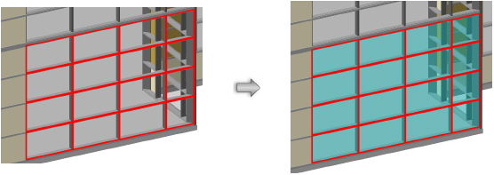
 Editing Curtain Walls
The Edit Curtain Wall tool is in the Building Shell tool set.
The Edit Curtain Wall tool manipulates the frames and panels of curtain walls. Once a curtain wall is selected with the tool, the modes allow you to select frames and panels; delete frames and panels; add, split, and combine frames; move frame and panel sets along a wall; and edit frame and panel settings.
When a curtain wall is selected with the Selection tool, two context menu commands become available. The Edit Using Reshape Tool command activates the Reshape tool to reshape the walls as described in Reshaping Walls. The Edit Using Edit Curtain Wall Tool command activates the Edit Curtain Wall tool.

Mode |
Description |
|---|---|
Select Frame |
Selects one or more frames |
Select Panel |
Selects one or more panels |
Add Frame |
Inserts new frames into the curtain wall |
Split Frame |
Splits a frame into multiple pieces, so that one portion of the frame can be independently moved, edited, or deleted |
Combine Frames |
Combines two collinear frames into a single frame |
Move Grid |
Moves an entire set of frames and panels relative to the curtain wall |
Settings |
Selected frame or panel parameters can be edited |
|
Click here for a video tip about this topic (internet access required). |
~~~~~~~~~~~~~~~~~~~~~~~~~
 Editing
Curtain Wall Frames
Editing
Curtain Wall FramesMode |
Tool |
Tool set |
|---|---|---|
Select Frame
|
Edit Curtain Wall
|
Building Shell |
To select and manipulate curtain wall frames:
1 Click the tool and mode.
2 Select the curtain wall to edit.
3 Select the frame or frames to edit, move, or delete.
The Edit Curtain Wall tool works similarly to the Selection tool. Frames can be selected for editing in a variety of ways. When a single frame is selected, end handles allow the frame to be reshaped.
Method |
Selection Action |
|---|---|
Click |
Standard selection method; selects a single object only |
Shift-click |
Selects multiple objects as each object is clicked; also can be used to deselect one or more objects without affecting other selected objects |
Option-drag (Mac) or Ctrl-drag (Windows) |
Places a copy of the object where the mouse button is released |
Rectangle marquee |
Selects all objects that are completely contained within the marquee |
Shift-marquee |
Reverses the selection status of objects inside a marquee; if objects inside the marquee are selected, this method deselects those objects |
Option-marquee (Mac) or Alt-marquee (Windows) |
Selects all objects that the marquee passes through, as well as those contained within the marquee |
4 A single, selected frame can be reshaped, moved by dragging, copied, or deleted. The frame must be connected on both ends to another frame. If deleting or moving a frame causes any frames to become disconnected, they are automatically extended until they join a frame.
Selected frames can be deleted by pressing the Delete key, or alternatively, right-click on the frame and select Delete Frames from the context menu.
Selected frames can be evenly distributed relative to the wall. Frames must be horizontal or vertical, and at least three frames must be selected. Right-click on the frames and select Distribute Frames from the context menu. The frames on the ends of the selection do not move.
Panels automatically adjust to conform to the new frame positions.
5 The settings of selected frames can be edited by clicking the Settings mode from the Tool bar.
Alternatively, right-click on the frame and select Edit Frames from the context menu.
~~~~~~~~~~~~~~~~~~~~~~~~~
 Editing
Curtain Wall Panels
Editing
Curtain Wall PanelsMode |
Tool |
Tool set |
|---|---|---|
Select Panel
|
Edit Curtain Wall
|
Building Shell |
To select and manipulate curtain wall frames:
1 Click the tool and mode.
2 Select the curtain wall to edit.
3 Select the panel or panels to edit. Panels cannot be moved; the position of the panels is determined by the frames. Selecting panels is very similar to selecting frames; see Editing Curtain Wall Frames.
4 The settings of selected panels can be edited by clicking the Settings mode from the Tool bar.
Alternatively, right-click on the frame and select Edit Panels from the context menu.
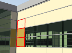
When one or more curtain wall panels are selected, a door or window can be easily inserted. Right-click on the panel and select Insert Window or Insert Door from the context menu. The window or door is automatically inserted as a curtain wall window or door, and sized to fit within the selected panel or panels.
~~~~~~~~~~~~~~~~~~~~~~~~~
 Adding
New Frames to a Curtain Wall
Adding
New Frames to a Curtain WallMode |
Tool |
Tool set |
|---|---|---|
Add Frame
|
Edit Curtain Wall
|
Building Shell |
To add new curtain wall frames:
1 Click the tool and mode.
2 Select the curtain wall to edit.
3 Click at the start point of the new frame, and then click the end point of the new frame. The start and end points must be placed on existing frames.
Press the Shift key to constrain the placement of the second point of the frame horizontally or vertically.
4 The frame is added, acquiring its attributes from the curtain wall grid settings.

~~~~~~~~~~~~~~~~~~~~~~~~~
 Splitting
Curtain Wall Frames
Splitting
Curtain Wall FramesMode |
Tool |
Tool set |
|---|---|---|
Split Frame
|
Edit Curtain Wall
|
Building Shell |
To split curtain wall frames:
1 Click the tool and mode.
2 Select the curtain wall to edit.
3 Click a frame to split it into sections.
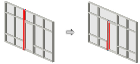
A frame can only be split at a frame intersection. A red split cursor displays to indicate locations where the frame can be split.
4 The frame is split, and the resulting sections can be dragged, deleted, or have their settings changed independently.

~~~~~~~~~~~~~~~~~~~~~~~~~
 Combining
Curtain Wall Frames
Combining
Curtain Wall FramesMode |
Tool |
Tool set |
|---|---|---|
Combine Frame
|
Edit Curtain Wall
|
Building Shell |
To combine curtain wall frames:
1 Click the tool and mode.
2 Select the curtain wall to edit.
3 Click the two frames to be combined. Frames must be collinear.
At a four-way frame intersection, it may be necessary to split a perpendicular frame to be able to join collinear frames.
4 One frame is created. The attributes of the first clicked frame apply to both frames once they are combined.

~~~~~~~~~~~~~~~~~~~~~~~~~
 Moving
a Curtain Wall Grid
Moving
a Curtain Wall GridMode |
Tool |
Tool set |
|---|---|---|
Move Grid
|
Edit Curtain Wall
|
Building Shell |
The frames and panels of a curtain wall form a grid or pattern relative to the wall. Moving the grid along the wall can be useful to center a grid pattern on a wall.
To move the curtain wall grid relative to the wall:
1 Click the tool and mode.
2 Select the curtain wall to edit.
3 Click to set a reference point for the grid.
4 Move the cursor to shift the entire grid of frames and panels, along with any doors and windows, relative to the wall.
The frames and panels shift to the left or right along the wall. A preview of the grid displays.
5 Click to set the new location of the curtain wall grid.

~~~~~~~~~~~~~~~~~~~~~~~~~
 Changing
Selected Frame or Panel Settings
Changing
Selected Frame or Panel SettingsMode |
Tool |
Tool set |
|---|---|---|
Settings
|
Edit Curtain Wall
|
Building Shell |
The Settings mode changes the settings of either frames or panels that have been selected with the Select Frame or Select Panel mode of the Edit Curtain Wall tool.
To change curtain wall frame or panel settings:
1 Click the tool, and then click either Select Frame or Select Panel mode.
2 Select the curtain wall to edit.
3 Select the frames or panels to edit, and click Settings mode.
Alternatively, right-click on the frame or panel and select Edit Frames or Edit Panels from the context menu.
4 The Frame Settings or Panel Settings dialog box opens. Change the settings as described in Setting Curtain Wall Frame Parameters or Setting Curtain Wall Panel Parameters.
The Frame Settings dialog box, when opened in this way, does not include the frame category selection on the left, since the frames to edit have already been selected.
~~~~~~~~~~~~~~~~~~~~~~~~~
 Creating Columns and
Pilasters
Creating Columns and
PilastersMode |
Tool |
Workspace: Tool set |
|---|---|---|
Modes for The Symbol Insertion Tool |
Column
|
• Landmark, Spotlight: Building Shell (basic column) • Architect: Building Shell (additional capabilities) |
Modes for The Symbol Insertion Tool |
Pilaster
|
Architect: Building Shell |
In the Vectorworks Architect product, columns and pilasters can be architectural in nature, structural in nature, or both. Use the Column tool or Pilaster tool to draw an object that not only reflects the architectural appearance of a column/pilaster, but also defines it in structural terms that can be used in an engineering analysis of the building. Structural and architectural elements can be displayed or hidden. The column ID can also, optionally, be placed on the drawing. Additionally, in the Architect product, the column/pilaster can be exported to IFC format for exchange with structural analysis programs.
A pilaster can be placed in a wall (however, a column cannot be placed in a wall). A pilaster inserted in a wall can set its architectural height relative to the wall.
To create a column or pilaster:
1 Click the tool and the desired symbol insertion and alignment modes.
2 From the Tool bar, click either Active Def to select an existing resource from the Resource Selector, or click Preferences and set the default parameters to create a custom object.
3 Click on the drawing to place the object, and click again to set the rotation. The properties can be edited from the Object Info palette.
To create a circular or square shaft, capital, or base, enter the same value for the width and depth.
Optionally, after placement you can create a plug-in object style, which combines style parameters (with a fixed value established by the style) and instance parameters (which can be set independently for each instance of the styled object in the drawing). See Creating Plug-in Object Styles.
The basic column object is available with the Vectorworks Landmark and Spotlight products.

► Clique para exibir/ocultar parâmetros.
 Architect Column and Pilaster
Parameters
Architect Column and Pilaster
Parameters The architectural column and pilaster objects are available with the Vectorworks Architect product.

► Clique para exibir/ocultar parâmetros.
~~~~~~~~~~~~~~~~~~~~~~~~~
 Exporting
Columns and Pilasters to IFC Format
Exporting
Columns and Pilasters to IFC FormatIn the Vectorworks Architect product, columns and pilasters can be exported to IFC format for exchange with structural analysis programs. If the column/pilaster has both architectural and structural components enabled, the object is exported as an IfcColumn and the architectural component is exported as an IfcCovering with an IfcCoveringType of Cladding. If the column/pilaster has only an architectural or structural component enabled, the object is exported as an IfcColumn.
~~~~~~~~~~~~~~~~~~~~~~~~~
 Creating Pillars
Command |
Workspace: Path |
|---|---|
Pillar |
• Architect: AEC • Landmark: Landmark > Architectural • Spotlight: Spotlight > Architectural |
The Pillar command converts any closed 2D shape—rectangle, circle, oval, or polygon—into a pillar. In addition, use it on open 2D shapes, such as lines and polylines, to create a flat, screen-like object. These objects include such things as movie screens, room dividers, and moving walls. Once created, a pillar can be joined to a wall.

To create a pillar:
1 Click the object to convert.
2 Select the command.
The Pillar Preferences dialog box opens.
3 Enter a pillar height.
To edit the pillar after creation, select Modify > Edit Pillar. See Object Editing Mode.
~~~~~~~~~~~~~~~~~~~~~~~~~
 Joining
Pillars and Walls
Joining
Pillars and WallsWalls and pillars can be joined together. Any number of walls can connect to the pillar as long as space exists on the pillar.
The pillar needs to be joined to the end of a wall; it cannot be added to an existing wall intersection such as the corner of L-joined or T-joined walls.

To join a pillar to a wall:
1 Click the pillar.
2 Draw the walls.
If the Auto-join feature is enabled, then the walls automatically connect to the pillar.
If the Auto-join feature is disabled, then click the Wall Join tool from the Walls tool set or the Building Shell tool set and join the walls to the pillar.
~~~~~~~~~~~~~~~~~~~~~~~~~


