Comando
Path
View bar
Organização
Ferramentas


O software Vectorworks fornece uma variedade de estratégias para organizar seu desenho. Quando usados em combinação, esses elementos organizacionais, que podem ser criados e gerenciados na A Janela de Diálogo Organização, facilite o foco nas partes do desenho que você precisa para desenhar, visualizar, compartilhar e apresentar.
• Camadas de Projeto são comparáveis às folhas que são usadas para elaboração à mão; Cada item pertence a uma camada da mesma maneira que um item elaborado à mão pertence à sua folha.
• Classes abrangem as camadas de design e permitem controlar os atributos e a visibilidade de objetos em várias camadas.
• Camadas de Folha são criadas para a apresentação de um projeto finalizado e podem conter viewports, bordas de blocos de títulos, notas e outras anotações.
• Viewports usam uma combinação de camadas e classes de projeto visíveis, acinzentadas e/ou ocultas para exibir detalhes, seções ou exibições finais renderizadas de um desenho para apresentação.
• Vistas Salvas armazenam um ou mais aspectos da exibição atual, como as configurações de visibilidade, zoom e camada e visibilidade da classe, para que você possa retornar instantaneamente a uma exibição.
• Referências permitem que você use elementos de desenho de outro arquivo no arquivo atual; Quando um item referenciado no arquivo gabarito é alterado, as alterações são refletidas no arquivo de destino.
• Andares, disponíveis no produto Vectorworks Architect, associam andares de construção a camadas de projeto para organizar e controlar elementos de desenho arquitetônico.
Os blocos de construção básicos de qualquer desenho são uma camada de projeto e uma estrutura de classes eficientes e um sistema para atribuir objetos às camadas e classes apropriadas. A camada de projeto contém o objeto, enquanto a classe determina a aparência do objeto. Cada objeto de desenho é atribuído a uma camada e uma classe.
Recomenda-se configurar as camadas e classes de projeto no início de um projeto, para que os objetos possam ser atribuídos a camadas e classes apropriadas à medida que são criados. Estruturas de camada e classe podem ser salvas em um modelo para uso em arquivos futuros (veja Creating Templates).
Ambas as camadas e classes de projeto podem ser usadas para controlar a visibilidade dos objetos. A camada de projeto atualmente ativa e a classe ativa são visíveis; outras camadas e classes de design podem ser definidas para serem visíveis, invisíveis ou cinza. Uma vez estabelecida uma camada eficaz e um sistema de classes, você pode selecionar as camadas e classes apropriadas para exibição, seleção, desenho, compartilhamento, impressão e apresentação. Isso permite que um único arquivo seja usado para muitos propósitos.
~~~~~~~~~~~~~~~~~~~~~~~~~
Comando |
Path |
View bar |
|---|---|---|
Organização |
Ferramentas |
|
Crie e gerencie elementos estruturais do desenho usando a caixa de diálogo Organização. Esta caixa de diálogo tem funções especializadas para classificar e selecionar seus itens de lista; veja List Box Functionality.
Para usar a caixa de diálogo Organização:
1 Selecione o comando ou clique no botão da barra de visualização.
Ou selecione Editar Vista no menu Vistas Salvas também na barra de Visualização.
A caixa de diálogo Organização abrirá.
2 Selecione a aba apropriada para o elemento estrutural do Vectorworks que deseja criar ou editar
3 No topo da janela, selecione a opção desejada de visualização dos parâmetros: Detalhes ou Visibilidade.
De uma forma geral, a opção de visualização Detalhes mostra o estado de cada elemento, e permite controlar a visibilidade das classes e camadas na área de desenho; a opção Visibilidade permite controlar a visibilidade de classes e camadas tanto em viewports como em vistas salvas. (veja Visibility Columns).
4 Botões na parte inferior de cada guia fornecem criação e funções de gestão. Como alternativa, o botão direito do mouse (Windows) ou Ctrl + clique (Macintosh) em um item da lista para exibir um menu de contexto, que tem a maioria das mesmas funções que os botões da guia.
Se uma descrição foi definida para a classe, ela é exibida em uma dica de tela quando você posicionar o cursor sobre o nome da classe. No Windows, clique na seta para divulgação na ponta da tela para recolher ou expandir.
► Clique para exibir/ocultar botões
Os nomes da camadas de projeto referenciados são exibir em itálico. Se uma descrição foi inserida para a camada de design, ela é exibida em uma dica de tela quando você posicionar o cursor sobre o nome da camada. Se a camada é referenciada, a dica de tela também exibe o nome da camada completo e o nome do arquivo de origem. No Windows, clique na seta para divulgação na ponta da tela para recolher ou expandir.
► Clique para exibir/ocultar os botões.
 Aba
Andares
Aba
AndaresNo produto Vectorworks Architect, uma aba adicional de Andares está disponível; veja Setting Up the Building Structure with Stories.
O nome da camada de folha é exibido em azul se a camada for reservada de um projeto compartilhado. Se uma descrição for inserida para a camada da folha, ela será exibida em uma dica de tela quando você posicionar o cursor sobre o nome da camada. No Windows, clique na seta de expansão da dica da tela para reduzi-la ou expandi-la.
► Clique para exibir/ocultar botões.
O nome da janela de visualização é exibido em azul quando é retirado de um projeto compartilhado.
► Clique para exibir/ocultar botões.
► Clique para exibir/ocultar botões.
► Clique para exibir/ocultar botões.
|
Clique aqui para uma dica em vídeo sobre este tópico (requer acesso a internet) |
~~~~~~~~~~~~~~~~~~~~~~~~~
Na janela Organização e na paleta Navegação (requer Design Series) as classes com nomes compostos separados por um traço (como por exemplo Walls-Ext) podem ser exibidas em ordem hierárquica (em até quatro níveis) da mesma forma como são exibidas nos menus Classes. Cada nível de classe terá um cabeçalho de grupo no nível superior quando este for exibido em ordem hierárquica. Algumas opções estarão disponíveis para controlar a exibição hierárquica das classes em vários níveis.
Para ativar / desativar a exibição ordem hierárquica em menus pop-up em todo software Vectorworks:
• Na guia Sessão da caixa de diálogo Preferências Vectorworks, selecionar / desmarcar classes de exibição em menus pop-up hierarquicamente para alternar entre a visualização hierárquica e não hierárquica. Esta definição controla todos os menus pop-up de todo o software.
Para ativar a exibição hierárquica:
• Na aba Classes da janela Organização, clique no botão alternar no canto inferior direito ou selecione a opção Exibição Hierárquica para alternar entre as exibições hierárquica e não-hierárquica, com os itens expandidos ou recolhidos conforme a sua última exibição.
• Na paleta Navegação (requer Design Series) selecione a opção Exibição Hierárquica no menu de contexto para alternar entre as exibições hierárquica e não-hierárquica, com os itens expandidos ou recolhidos conforme a sua última exibição.

Ao exibir as classes em ordem hierárquica, a ordenação não estará disponível.
Para expandir ou minimizar um único cabeçalho de grupo de classe na exibição em ordem hierárquica:
• Clique na seta de expansão à esquerda do cabeçalho de grupo de classe
• Dê um duplo clique no cabeçalho de grupo de classe
Para expandir todas as classes no arquivo ou para minimizar a lista para somente as classes de nível superior (aquelas sem o traço no nome) e exibir os cabeçalhos de grupo de classe na exibição de ordem hierárquica:
• Clique segurando Shift e Option (Macintosh) ou segurando Shift e Alt (Windows) na seta de expansão à esquerda do cabeçalho de grupo de classe
• Dê um duplo clique segurando Shift e Option (Macintosh) ou segurando Shift e Alt (Windows) no cabeçalho de grupo de classe
Os comandos Expandir Todos e Minimizar Todos realizam as mesmas funções.
Para expandir ou minimizar todos os subgrupos de classes na ordem de exibição hierárquica:
• Clique segurando Option (Macintosh) ou segurando Alt (Windows) na seta de expansão à esquerda do cabeçalho de grupo de classe
• Dê um duplo clique segurando Option (Macintosh) ou segurando Alt (Windows) no cabeçalho de grupo de classe
Para gerenciar as opções de visibilidade na ordem de exibição hierárquica:
• Se todos os subníveis de classe tiverem as mesmas opções de visibilidade, então o cabeçalho de grupo de classe também terá a mesma opção de visibilidade. Caso contrário, a coluna Visibilidade ficará em branco para o cabeçalho de grupo de classe
• Atribua ou altere a opção de visibilidade usando a coluna Visibilidade do cabeçalho de grupo de classe, e os subníveis irão herdar as opções de visibilidade
~~~~~~~~~~~~~~~~~~~~~~~~~
Aspectos específicos da estrutura de desenho (classes, camadas de folhas, e camadas de projeto) podem ser importados de um ou mais arquivos existentes. Os arquivos de onde se importam os dados podem ser arquivos padrão fornecidos com o Vectorworks, ou outros arquivos que você tenha criado com o Vectorworks.
Os arquivos gabarito (formato .sta) são localizados na pasta Standards (dentro de [Vectorworks]/Libraries/Defaults). Os padrões de camadas usam apenas nomes aprovados e ajustes de classes para aplicações específicas. Classes ou camada personalizadas podem ser criadas em um documento em branco e então salvas para um arquivo .sta na pasta Standards. Uma vez colocados na pasta Standards, estas novas camadas ou classes tornam-se parte da lista de Standards e são disponíveis quando novas camadas ou classes são criadas.
Caso algum de seus arquivos de trabalhos torne-se corrompido, um método possível de recuperação é o de importar os dados em um novo arquivo. Crie um novo arquivo e então importe as classes, camadas de folha, e camadas de projeto (e opcionalmente, objetos de camadas de projeto) a partir do arquivo original se necessário.
Para importar estruturas de desenho, use a janela de Organização para criar uma nova classe, camadas de folha, ou camadas de projeto. Ao contrário de criar um novo item, entretanto, selecione a opção Importar. Selecione o arquivo do qual importar a estrutura, e então selecione as classes e camadas específicas que deseja importar do arquivo. Para camadas de projeto, selecione se deseja importar objetos na camada também.
veja Criando Camdas e Creating Classes outros detalhes.
|
Clique aqui para uma dica em vídeo sobre este tópico (requer acesso a internet) |
O software Vectorworks faz uma distinção entre dois tipos de camadas, cada uma com seu próprio propósito:
• Camadas de Projeto são usados para desenhar os modelos dos projetos. Eles contêm os itens de desenho e pode ser empilhado, escondido, escalado, e reordenadas.
• Camadas de Folhas são usados para criar uma versão de apresentação do desenho finalizado. Isso pode incluir janelas de exibição, blocos de títulos, notas e outras anotações. Camadas de folhas estão sempre em uma escala de 1:1, Apenas Ativa e definir a vista topo/planta (veja Creating Sheet Layer Viewports), embora as janelas de visualização exibidas em uma camada de folha possam ser exibidas em diferentes escalas, modos de exibição, modos de renderização etc. As camadas de folha exibem uma borda cinza ampla representando a área da margem de impressão.
Camadas têm certas características que são usadas ao desenhar e estruturar arquivos:
• Camadas de projeto são empilhadas por padrão na ordem em que são criadas (com novas camadas colocadas na parte superior), mas a ordem de empilhamento pode ser alterada. Reordene as camadas para mover todos os objetos contidos em cada camada para outro local sem realmente modificar os objetos ou o posicionamento deles na camada.

• A distance can be set between design layers rather than having them lie flat on top of each other. Design layers can automatically set default elevation values for objects they contain. They create natural structural divisions within a project for objects on different floors or different vertical locations within a floor.
• Design layers can be visible, invisible, or grayed. Create design layers with objects that should always display, or layers that contain objects for display only at particular times. Control the visibility of the design layers to limit the need for creating new objects. Sheet layers always show only the active layer.

• Design layers, as well as design layer viewports (Vectorworks Design Series required), can be displayed at different drawing scales, for the display of all aspects of a project plan from the site model to the details.
• Design layers can be viewed in 3D. For example, if the first floor, second floor, basement, and roof of a house are each placed in its own design layer, not only can the 2D drafting plan be printed for any one of those layers, but the design layers can be viewed together in 3D, creating a model of a fully formed house.
• Viewports can be used to display several views of the finished design, either on design layers (Vectorworks Design Series required) or on sheet layers. A building can be viewed in Plan view in one viewport and in an elevation or perspective view in another. The original design layers remain unchanged.
• You can reference specific design layers that exist in another Vectorworks file, with all of the classes and resources used in those layers, as well as any resources from the referenced file. When a referenced item in the master file changes, the changes are reflected in the target file. veja Concept: Layer Referencing.
• In the Vectorworks Architect program, design layers can optionally be associated with stories that contain objects; stories define absolute elevations in the building model, while layers can be set at an elevation relative to the story. This method of organizing a file makes it much easier to manage a building’s layers and certain associated objects like walls and columns. veja Setting Up the Building Structure with Stories.
• The Vectorworks Architect program allows a cut plane elevation to be specified for a design layer. When the cut plane is enabled for the layer, the auto hybrid objects, the structural members, the walls and curtain walls (including the objects, like windows, that are within the walls), and the wall features all display with their cut plane appearance, which is set by class or specified in the object settings.
|
Clique aqui para uma dica em vídeo sobre este tópico (requer acesso a internet) |
~~~~~~~~~~~~~~~~~~~~~~~~~
Quando um novo desenho é criado, ele automaticamente contém uma camada de projeto vazia com o nome de “Camada de Projeto-1”. Adicione camadas de projeto ao desenho conforme necessitar para organizá-lo. Adicione camadas de folhas conforme necessário para a apresentação do desenho. Crie novas camadas, projeto e camadas de folha, ou importe-as (e, opcionalmente, os objetos que elas contém) de outros arquivos do Vectorworks (da mesma versão) ou ainda de arquivos gabaritos. No Vectorworks Design Series, crie um viewports de camada de projeto para referenciar camadas de projeto de outros arquivos sem ter que importá-los.
Para criar uma nova camada:
1 Para uma maior conveniência, você poderá criar novas camadas a partir de diversos lugares no Vectorworks.
• Novo botão na guia Camada de Projeto/Camadas de Folha da janela de diálogo Organização (Ferramentas > Organização)
• Botão Camadas na Barra de Visualização para abrir a janela de diálogo Organização
• Opções Nova Camada de Projeto ou Nova Camada de Folha na lista suspensa de Camadas na Barra de Visualização
• Campo de Camada na guia Forma da Paleta Info de Objeto
• Novo Menu Contextual na guia Camada de Projeto ou Camadas de Folha da paleta Navegação (necessário Vectorworks Design Series)
2 Nas janelas de diálogo Nova Camada de Projeto ou Nova Camadas de Folha, crie uma nova camada ou importe uma camada e suas propriedades de arquivos padrão ou existentes do Vectorworks.
► Clique para exibir/ocultar parâmetros.
As camadas são exibidas na lista Camadas, na caixa de diálogo Organização, na barra Exibir, na paleta Informações sobre objetos e (para Vectorworks Design Series), na paleta Navegação. Se a camada for criada em qualquer lugar diferente da paleta Informações do objeto, ela se tornará a camada ativa.
~~~~~~~~~~~~~~~~~~~~~~~~~
To be able to add, remove, or edit objects on a design layer, either the layer must be active or the layer options must be set to allow modifications to other layers (veja Setting Global Visibility with Class and Design Layer Options). There are several ways to change the active design layer or sheet layer.
• If there are only a few layers, switch among layers with the Switch active layer/class shortcut key combination specified in Vectorworks preferences (veja Vectorworks Preferences: Edit Tab). This selects a layer by moving up or down through the layer list one layer at a time. If you select a filter from the Layers list in the View bar, the shortcut switches among layers on the filtered list.
• If the drawing has a large number of layers, use one of the following options. To quickly locate a layer in a list, veja Using Filters.
To set the active layer:
1 From the Organization dialog box, in Details view, select the Design Layers tab or the Sheet Layers tab.
The active layer is indicated by a check mark to the left of the Design Layer Name or Sheet Number. The layer also is highlighted in bold text.
2 To make a different layer active, click the column to the left of its name/number.
To set the active layer:
1 Click the Layers list from the View bar to display a list of all of the sheet layers and design layers in the drawing.
The active layer is highlighted in bold text.
2 Click the name of the layer to be activated.
The layers list closes and the active layer displays.
 Setting
the Active Layer in the Navigation Palette
Setting
the Active Layer in the Navigation PaletteTo set the active layer:
1 From the Navigation palette, select the Design Layers tab or the Sheet Layers tab.
The active layer is indicated by a check mark to the left of the Design Layer Name or Sheet Number. The layer also is highlighted in bold text.
2 To make a different layer active, click the column to the left of its name/number.
Alternatively, right-click on the layer to be activated and select Activate from the context menu.
Command |
Path |
|---|---|
Activate Layer |
Document context menu |
If multiple design layers are set to be visible, and the layer options are set to show those other layers, the drawing area may display objects that are on non-active layers. Use the Activate Layer command to make the layer of one of these objects active.
The Force Select command on the document context menu also changes the active class and layer (if necessary), and selects the clicked object.
To set the active design layer:
1 In the drawing area, right-click a visible object on a non-active design layer.
2 Select the command.
The object’s layer becomes active.

~~~~~~~~~~~~~~~~~~~~~~~~~
Comando |
Path |
View bar |
|---|---|---|
Organização |
Ferramentas |
|
Uma vez criadas, as camadas de projeto passam a ser listadas na aba Camadas de Projeto da janela Organização, onde diversas propriedades podem ser definidas e editadas.
Para editar as camadas:
1.Selecione Organizar > Organização.
A janela de Organização irá abrir.
2. Selecione a aba Camadas de Projeto.
Uma lista das camadas atuais do desenho serão exibidas em sua ordem de empilhamento. Dependendo de qual opção de visualização for selecionada na parte superior da janela de diálogo, tanto detalhes como visibilidades do display de camadas do projeto. A ordem de empilhamento, visibilidade da área do desenho, e a camada ativa podem ser alteradas na exibição de detalhes. A visibilidade de camadas nas viewports e vistas salvas pode ser alteradas na vista Visibilidades.
No produto Vectorworks Architect, Detalhamento da vista inclui os andares e seus níveis para cada camada que esteja associada a um andar de um nível.
Camadas que são importadas de outro arquivo com referenciamento de camada importada em itálico. Posicione o cursor sobre o nome da camada para exibir uma dica de tela com o nome da camada completo e o nome do arquivo de origem.
3 Para alterar outras propriedades da camada, selecione uma ou mais camadas e clique em Editar para abrir a janela de diálogo Editar Camadas de Projeto.
► Clique para exibir/ocultar parâmetros.
~~~~~~~~~~~~~~~~~~~~~~~~~
Camadas de Projetos são visualizadas e impressas na "Ordem de Sobreposição," de cima para baixo na janela de diálogo de configuração de Camadas. Inicialmente, as camadas são "sobrepostas" na ordem em que são criadas, mas a sua ordem pode ser alterada a qualquer momento.
Alterar a ordem de sobreposição das camadas de projeto:
1. Na janela de diálogo Organização, selecione a aba Camadas de Projeto na exibição de Detalhes para ver a ordem de sobreposição recente. A coluna # à direita do nome da camada indica a posição atual da camada na pilha, com 1 sendo a camada superior.
2. Use um dos seguintes métodos para alterar a ordem de sobreposição da camada:
• A coluna # deve ser a coluna de classificação atual para alterar a ordem de sobreposição; Se a lista não estiver ordenada por ordem de sobreposição, clique no # título da coluna para alterá-lo. Em seguida, clique na coluna # da(s) camada(s) a serem movidas e arraste-a para cima ou para baixo na lista. Uma linha horizontal indica onde a(s) camada(s) serão inserida(s) na ordem atual.
• Selecione a(s) camada(s) para mover, e clique em Editar (ou clique duas vezes em uma linha da camada) para abrir a janela de diálogo Editar Camadas de Projeto. No campo ordem de sobreposição, introduza um número para a nova posição de ordem de sobreposição da(s) camada(s). Clique em OK para aceitar as alterações.
A aba Camadas de Projeto exibe a nova ordem de sobreposição.

Este recurso está disponível em todos os sistemas Mac, em sistemas Windows apenas quando a preferência GDI + imagem está habilitada. (veja Vectorworks Preferences: Display Tab fpara obter informações sobre como definir essa preferência.) Camadas de Projeto têm uma configuração que controla a transparência de objetos da camada que sobrepõem objetos visíveis em outra camada. Um valor de opacidade de 100% significa que nada abaixo da camada ativa é visível. Diminuir o valor de opacidade para aumentar a transparência dos objetos na camada.
Para definir a Opacidade de uma Camada de Projeto:
1. Na janela de diálogo Organização, selecione a aba Camadas de Projeto. Selecione uma ou mais camadas, e em seguida, clique em Editar.
A janela de diálogo Editar Camadas de Projeto é exibida.
2. Arraste o controle deslizante Opacidade para a esquerda para aumentar a transparência, ou digite um percentual de opacidade (0-100) na caixa à direita do controle deslizante.
3. Clique em OK para fechar a janela de diálogo Editar Camadas de Projeto e clique em OK novamente para fechar a janela de diálogo Organização.
Objetos individuais também podem ter uma porcentagem de opacidade aplicada, veja Opacity Attributes.
~~~~~~~~~~~~~~~~~~~~~~~~~
This feature is only available on Windows systems. When the GDI+ imaging preference is disabled, design layers have a setting that controls the display of layer objects that overlap visible objects in another layer. (veja Vectorworks Preferences: Display Tab for information about setting this preference.)
To set the transfer mode for a design layer:
1 From the Organization dialog box, select the Design Layers tab. Select one or more layers, and then click Edit.
The Edit Design Layers dialog box opens.
2 Select the desired Transfer Mode from the list.
Mode |
Description |
|---|---|
Paint |
Makes objects in the new layer solid, obscuring objects in layers stacked below it (this is the default setting)
|
Overlay |
Makes it so objects in the new layer do not obscure stacked layers
|
Invert |
Makes a reversed, or photo-negative, image display when an object in the new layer overlaps an object in another layer
|
Erase |
Makes objects in the new layer display all foreground patterns as white and all background patterns as transparent
|
Not Paint
|
Makes objects in the new layer solid and inverts any areas that overlap objects in stacked layers
|
Not Overlay |
Makes objects in the new layer transparent and inverts layer colors
|
Not Invert |
Makes objects in the new layer transparent and converts any black pixels from overlapping areas to white and white pixels to transparent
|
Not Erase |
Makes objects in the new layer transparent and converts any white pixels from overlapping areas to black and black pixels to transparent
|
Most printer devices do not support all of these modes, especially PostScript printers and vector devices such as pen plotters. The Rasterize print output option may produce the best results for certain transfer modes. The use of color in transfer modes may produce color blending.
~~~~~~~~~~~~~~~~~~~~~~~~~
The fill and pen color of objects that are drawn on or moved to a design layer can be controlled by the color settings of the design layer. The Use layer colors setting in the Document Preferences dialog box must be turned on (veja Document Preferences: Display Tab).
These settings are overridden by the Black and white only option in the Document Preferences dialog box, even with the Use layer colors option selected.
To control the color of objects by their design layers:
1 From the Organization dialog box, select the Design Layers tab. Select one or several layers, and then click Edit.
The Edit Design Layers dialog box opens.
2 Click Colors.
The Color Defaults for Layer dialog box opens.
3 For both the fill and pen, set the Foreground and Background colors by clicking the appropriate list and selecting a color from the main Color Menu dialog box. A preview example is shown at the bottom of the dialog box.
The fill background color controls the appearance of objects with a solid fill.
When the Use layer colors preference is selected, all objects on the layer are drawn with the specified colors.
Viewports have separate control of layer color (veja Advanced Sheet Layer Viewport Properties).
|
Clique aqui para uma dica em vídeo sobre este tópico (requer acesso a internet) |
~~~~~~~~~~~~~~~~~~~~~~~~~
Command |
Path |
View bar |
|---|---|---|
Organization |
Tools |
|
Once created, the sheet layers display on the Sheet Layers tab of the Organization dialog box, where various layer properties can be set and edited.
Sheet layers are always at a 1:1 scale, Active Only, and set to Top/Plan view.
To edit sheet layers:
1 Select the command or click the View bar button.
The Organization dialog box opens.
2 Select the Sheet Layers tab and the Details view.
The Sheet Layers tab opens, with a list of the current layers in the drawing. The layer stacking order and the active layer can be changed in Details view. Visibilities view does not apply to sheet layers.
3 To change layer properties, select one or more layers and click Edit to open the Edit Sheet Layers dialog box.
► Clique para exibir/ocultar parâmetros.
|
Clique aqui para uma dica em vídeo sobre este tópico (requer acesso a internet) |
Sheet layers are viewed and printed in stacking order, the top-to-bottom order in the Organization dialog box. Initially, layers are stacked in the order in which they are created, but their order can be changed at any time.
To change the stacking order of sheet layers:
1 From the Organization dialog box, select the Sheet Layers tab in Details view to veja the current stacking order. The # column to the right of the sheet title indicates the layer’s current position in the stack, with 1 being the top layer.
2 Use one of the following methods to change the layer stacking order:
• The # column must be the current sorting column to change the stacking order; if the list is not currently sorted by stacking order, click the # column heading to change it. Then click the # column of the layer to be moved, and drag it up or down the list. A horizontal line indicates where the layer will be inserted in the current order.
• Select the layer to move, and then click Edit (or double-click a layer row) to open the Edit Sheet Layers dialog box. In the Stacking Order field, enter the number for the new stacking order position of the layer.
The Sheet Layers tab displays the new stacking order.

~~~~~~~~~~~~~~~~~~~~~~~~~
Classes are a powerful way to organize the elements in a drawing project according to category. Because classes apply to the entire file and work across design layers, they allow the grouping of similar objects in a drawing that for practical reasons need to exist on separate layers. This allows the objects to be viewed, changed, and tracked as a group.
Vectorworks classes are similar in function to—and are exported as—AutoCAD layers. If a drawing will be exported to AutoCAD, use classes to make it easy to turn on or off selected portions of the drawing. For example, if a consultant using AutoCAD will be doing the duct layout for a building, a furniture class in Vectorworks allows him or her to turn off the furniture layer in AutoCAD, instead of deleting furniture objects.
Classes have certain characteristics that are used when drawing and structuring files:
• Classes can be used to control visibility. For example, the classes shown for a review of the overall event design impede the clear view needed by the people who install individual components. In this case, you could assign lighting devices to the “Lighting” class, then make the class invisible in the documentation given to the rigging installers. This allows the same file to be used for all stages of a project and for various purposes.

• Classes can be used to assign graphical attributes, textures, and text styles to objects (veja Setting Class Attributes).
• As objects are created, they are normally assigned to the active class. The active class is highlighted in bold text on the Organization dialog box, Navigation palette, and the Classes list in the View bar. Note that the active class may not be displayed at all, if you have applied a filter to the list.
• Each new drawing created with the Vectorworks program automatically has two classes: Dimension and None. None is the default active class. Any dimensions created are assigned, by default, to the Dimension class (this is a preference setting that can be changed; veja Document Preferences: Dimensions Tab). These two classes can be renamed but not deleted.
• Complex objects, such as symbols or plug-in objects, may contain more than one class; if so, different parts of the object can be hidden or shown.
• If the drawing was created from a template, other classes may have been provided. New classes can be created, duplicated, edited, or deleted.
• If Vectorworks Design Series is installed, you can set up the drawing file to have a set of standard classes, which can be automatically assigned to specific types of objects as they are created. veja Layer, Class, and Viewport Standards.
• Class information can be used as a criterion for worksheets. For example, you might create a schedule showing the cost of all fixtures in the plumbing class (veja Concept: Worksheet Overview).
|
Clique aqui para uma dica em vídeo sobre este tópico (requer acesso a internet) |
~~~~~~~~~~~~~~~~~~~~~~~~~
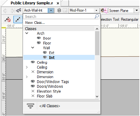
Decide on a naming scheme before you create classes. If there are a large number of classes, organize them by naming each class with a compound name consisting of up to four parts, separated by a dash. Each name part represents a different level in the class naming structure. For example, a drawing of a building might have a class structure that includes main groups for architecture, plumbing, and electrical objects. Within the architecture group, there might be door, floor, and wall groups. Those groups in turn have subgroups—for example, the wall subgroup might have interior and exterior designations. A class is named according to its position in the class structure, as in Arch-Wall-Ext, Elec-Lite-Ceiling, or Plum-Equip-New.
Class names impact hierarchical display on pop-up menus (including from the Object Info palette, the View bar, and dialog boxes) and in the Organization dialog box and (for Vectorworks Design Series products) the Navigation palette. To enable or disable hierarchical display on pop-up menus, veja Vectorworks Preferences: Session Tab; for the Organization dialog box and Navigation palette, veja Exibindo Classes em Ordem Hierárquica.
In the following example, the Arch group has a Wall subgroup, with Ext and Int options. This type of organization makes it easy to assign classes as objects are created.
Classes can be created as new, or imported from other current version Vectorworks files or standard files.
To create a new class:
1 For convenience, a new class can be added from multiple locations in the software.
• New button on the Classes tab of the Organization dialog box (Tools > Organization)
• Classes button on the View bar to open the Organization dialog box
• New Class option from the Classes drop-down list on the View bar
• Class field on the Shape tab of the Object Info palette
• New context menu on the Classes tab of the Navigation palette (Vectorworks Design Series required)
2 From the New Class dialog box, create a new class, or import a class and its properties from standard or existing Vectorworks files.
Class Type |
Action |
|---|---|
Create New Class |
Creates a class based on current Attributes palette settings; enter a class Name |
Import Classes |
Imports classes and their attributes from standard files or existing files. Files located in the Standards folder, as well as existing files selected previously, are displayed in the list. Select a file; the available classes and descriptions are listed beneath the file name. Select the desired class(es). To select multiple classes from the import list, hold the Ctrl (Windows) or Command (Mac) key while you click. |
Show only classes that are not in the current document |
If a class name in the current file matches a class in the import file, normally that class is not included on the list as an import option. To display all the classes to be imported, deselect this option. The existing classes in the file are replaced by any imported classes with the same name, changing the existing class definitions (and any associated objects) to those of the imported classes. |
Choose |
Click Choose to select a file for class import. Files must be in the current version. |
Creation Options |
|
Saved View Visibility |
Sets the visibility of the new class in saved views (when saved views exist in the drawing) |
Viewport Visibility |
Sets the visibility of the new class in viewports (when viewports exist in the drawing) |
Edit Properties After Creation |
Immediately after creation, opens the Edit Class(es) dialog box to set the properties of the new class(es) |
The classes display in the Classes list on the Organization dialog box, View bar, Object Info palette, and (for Vectorworks Design Series) the Navigation palette. When a new class is created, it does not automatically become the active class.
~~~~~~~~~~~~~~~~~~~~~~~~~
Command |
Path |
View bar |
|---|---|---|
Organization |
Tools |
|
Once created, the classes display on the Classes tab of the Organization dialog box, where various properties can be set and edited.
To edit classes:
1 Select the command or click the View bar button.
The Organization dialog box opens.
2 Select the Classes tab.
A list of the current classes in the drawing displays. Depending on which view option is selected at the top of the dialog box, either details or visibilities of the classes display. The visibility of classes in the drawing area and the active class can be changed in Details view. The visibility of classes in viewports and in saved views can be changed in Visibilities view (veja Visibility Columns).
3 To change other class properties, select one or more classes and click Edit to open the Edit Class(es) dialog box.
► Clique para exibir/ocultar parâmetros.
4 Click OK to return to the Organization dialog box. If objects in an edited class already exist in the drawing, and the class is set to use attributes “at creation,” you are prompted to specify how to apply the changes to the existing objects.
If multiple classes are simultaneously selected for editing, and some or all of the attribute values are different for the selected classes, the editing fields for those values indicate that the value is unknown. When the OK button is clicked, the currently defined settings shown are applied to all of the selected classes. Any information with an unknown setting is not applied.
~~~~~~~~~~~~~~~~~~~~~~~~~
There are two categories of attributes available for each object: object attributes and class attributes. Object attributes are assigned directly to an object from the Attributes palette, Object Info palette, or Resource Manager (depending on the type of attribute). Class attributes are determined by the object’s class settings.
Various attributes that an object uses when it is created are controlled by the Use at Creation options in the Edit Class(es) dialog box (veja Setting Class Properties):
• 2D graphic attributes
• Text in text objects, dimensions, callouts, and other annotation objects
• Textures in walls, roofs, and other 3D shapes
When one of these “use at creation” options is selected for a class, objects created in that class or subsequently assigned to that class use the class attributes. The Attributes palette displays with a curved arrow for attributes that have been set by class. If objects in that class already existed before the “use at creation” option is selected, you are prompted to decide whether to apply the attributes to the existing objects. If you edited attributes for more than one class at the same time, select Yes or No for each class individually, select Yes to All to apply the attributes from all edited classes at once, or No to All to leave the existing objects as they are.
Class attributes can also be assigned after objects are created:
• From the Attributes palette, select Class Style or Class Thickness from the appropriate attribute list.
• In the Shape tab of the Object Info palette, select <Class Text Style> from the Text Style list.
• In the Render tab of the Object Info palette, select Class Texture from the Texture list.
To override class attributes, select the object and apply different attributes directly from the Attributes palette, Object Info palette, or Resource Manager.
Several plug-in objects (such as Vectorworks Design Series doors and windows) offer the option to control the appearance and visibility of the smaller object parts either individually, or by the same class as the overall object. For example, select the <Door Class> option for the door jamb, lintel, and threshold to assign those door parts to the same class as the door object. If you change the door’s class later, the appearance and visibility of the smaller door parts automatically change according to the new class.

For more information, veja The Attributes Palette.
To be able to remove or edit objects in a particular class, either the class must be active or the class options must be set to allow modifications to other classes (veja Setting Global Visibility with Class and Design Layer Options). There are several ways to change the active class.
• If there are only a few classes, switch among classes with the Switch active layer/class shortcut key combination specified in the Vectorworks preferences (veja Vectorworks Preferences: Edit Tab). This selects a class by moving up or down through the class list one class at a time. If you select a filter from the Classes list in the View bar, the shortcut switches among classes on the filtered list.
• If the drawing has a large number of classes, use one of the following options. To quickly locate a class is a list, veja Using Filters.
To set the active class:
1 From the Organization dialog box, select the Classes tab in Details view.
The active class is indicated by a check mark to the left of the Class Name. The name of the class also is highlighted in bold text.
2 To make a different class active, click the column to the left of its name.
To set the active class:
1 Click the Classes list from the View bar to display a list of all of the drawing’s classes.
The active class is highlighted in bold text.
2 Click the class to be activated.
The classes list closes and the active class displays.
 Setting
the Active Class in the Navigation Palette
Setting
the Active Class in the Navigation PaletteTo set the active class:
1 From the Navigation palette, select the Classes tab.
The active class is indicated by a check mark to the left of the class name. The name of the class also is highlighted in bold text.
2 To make a different class active, click the column to the left of its name.
Alternatively, right-click on the class to be activated and select Activate from the context menu.
Command |
Path |
|---|---|
Activate Class |
Document context menu |
If multiple classes are set to be visible, and the class options are set to show those other classes, the drawing area may display objects that are in non-active classes. Use the Activate Class command to make the class of one of these objects active.
The Force Select command on the document context menu also changes the active class and the active layer (if necessary), and selects the clicked object.
To set the active class:
1 In the drawing area, right-click a visible object in a non-active class.
2 Select the command.
The object’s class becomes active.

Objects in a class can be copied and pasted from one drawing to another, even if the destination drawing does not contain the same class as the original drawing. The program automatically creates a new class in the destination drawing and transfers all of the class information from the source drawing. If the destination drawing already has a class with the same name as the source drawing, only the object information is pasted. All of the class information for the destination drawing’s class remains unchanged.
When you paste objects that could become invisible due to class visibility settings, specify whether the invisible classes should be made visible so that the pasted objects can be vejan.
 Setting
Up the Building Structure with Stories
Setting
Up the Building Structure with StoriesThe Vectorworks Architect product includes an additional document structural feature called stories. Stories define absolute elevations for the various floors of a building, and allow architects to manage defined story levels within those floors for construction elements like slabs, finish floors, and ceilings. The levels in a story have a Z height relative to the story; the story controls their absolute elevation, and if the story elevation changes, the levels and certain objects that are associated with them automatically change their elevation or boundaries along with the story.
Story levels can be optionally associated with a layer that contains objects (such as furniture, fixtures, and walls); these layers associated with stories are called story layers. To add objects to a story, at least one layer is required. The story levels that make up a story act as a top or bottom constraint for special bounded objects. These bounded objects can be defined at their boundaries by the levels that make up a story, such as a slab or a ceiling. For example, an exterior wall (or one of its components) can extend from the top of the slab on one story to the top of a slab on the story above it. Slabs, walls, wall components, curtain walls, spaces, stairs, escalators, and columns can be set according to a top and bottom boundary layer; the location of these boundaries is controlled by the elevation of the level and ultimately by the story elevation. Both walls and slabs can have their dynamic height information set and saved in a wall or slab style, so they can automatically take on their defined height condition. The insertion point of symbols can also be story aware, as enabled in the symbol definition, automatically setting the elevation to a story level (symbol instances can be set to a different story level from the Object Info palette). This method of using bounded objects allows flexibility and accuracy when defining a model, from the early to the final stages of design.
Begin project setup by creating the stories and their associated levels. Stories are created and managed from the Organization dialog box; either pre-defined standards or custom standards can be used. As the stories are added, any associated design layers are also created according to story level definitions. Finally, associate the applicable objects to the story level at the object’s top and bottom boundaries, creating a cohesive model that is structured and controlled by its building stories.
~~~~~~~~~~~~~~~~~~~~~~~~~
 Default Story Levels
Command |
Path |
|---|---|
Organization |
Tools |
Stories contain levels with names and parameters defined by standards. When a story has a level, it can be used as a potential boundary for objects in its story (such as walls, slabs, and so on) or for the story above or below it. You can select the automatically defined levels when creating a story, or create customized levels by defining the default story levels before creating the stories. Certain projects may require custom level types, which can also be set up in advance.
To create or edit default story levels:
1 Select the command to open the Organization dialog box. Click the Stories tab.
The functionality of the Organization dialog box is described in A Janela de Diálogo Organização.
2 Click Default Story Levels.
The Default Story Levels dialog box opens, listing the currently defined default levels, their elevations (offset from the story elevation), and any associated layer names.
3 Click New to create a new default story level, or Edit to modify the currently selected default level.
The New Default Story Level or Edit Default Story level dialog box opens.
► Clique para exibir/ocultar parâmetros.
4 By default, several level types are available, such as slab, finish floor, and ceiling; default story level types are provided as default content (veja Concept: Resource Libraries). To create a custom level type, select New Level Type from the Level Type list.
The New Level Type dialog box opens. Enter the name of the new type of level.
5 Click OK to return to the New/Edit Default Story Level dialog box.
6 Once the default story level has been defined or modified, click OK to return to the Default Story Levels dialog box.
7 Once the default story levels in the list have been defined or modified, click OK to return to the Organization dialog box.
Stories can now be created. They will use the default information specified to create the levels associated with the stories.
Command |
Path |
|---|---|
Organization |
Tools |
Available story levels can be managed from the Organization dialog box.
To manage available level types:
1 Select the command to open the Organization dialog box. Click the Stories tab.
2 Click Level Types.
The Level Types dialog box opens. Specify the level types that are available by default when creating stories.
► Clique para exibir/ocultar parâmetros.
~~~~~~~~~~~~~~~~~~~~~~~~~
 Creating
and Managing Stories
Creating
and Managing StoriesCommand |
Path |
|---|---|
Organization |
Tools |
Project setup begins with creating stories and specifying their associated story levels. The Stories tab of the Organization dialog box allows stories to be created and managed. Stories can also be created when creating or editing design layers with options that display only when the Vectorworks Architect product is installed. veja Definindo Propriedades da Camada de Projeto.
To create and manage stories from the Organization dialog box:
1 Select the command to open the Organization dialog box. Click the Stories tab.
The functionality of the Organization dialog box is described in A Janela de Diálogo Organização.
2 Visibilities view displays a list of story names. From the top of the dialog box, select Details view.
3 On the left, the stories are listed, along with the story’s prefix or suffix, and elevation. On the right, an interactive diagram displays the stories and associated layers that make up the building model.
 g
g
► Clique para exibir/ocultar parâmetros.
4 Click New to create a new story, or Edit to modify the currently selected story.
The New Story or Edit Story dialog box opens. Specify the name, elevation, prefix or suffix for any layers to be created, and associated levels. To add objects to a story, at least one layer is required.
► Clique para exibir/ocultar parâmetros.
5 If changing the elevation of a story from the Edit Story dialog box, the Change Story Elevation dialog box opens to determine how to adjust the story and the stories around it. If not changing the story elevation, proceed to step 7.
► Clique para exibir/ocultar parâmetros.
6 Click OK to return to the Edit Story dialog box.
The stories, once set up with associated levels and any layers with layer-defined objects, define the building model. On the Design Layers tab of the Organization dialog box, listed layers that are associated with levels display their story, level type, elevation, and default wall height.
~~~~~~~~~~~~~~~~~~~~~~~~~
 Layer,
Class, and Viewport Standards
Layer,
Class, and Viewport StandardsThe standards for the Vectorworks Architect and Landmark products take advantage of layer and class characteristics described in Conceito: Visão geral das camadas and Concept: Classes Overview.
Many plug-in objects that are included with Vectorworks Architect and Landmark products are set with pre-assigned classes. The appropriate classes are created at setup and by certain other commands (veja Automatically Created Classes). The use of automatic classing is determined with the Standard Naming setup command. For more information, veja Importando Estrutura de Desenho a partir de Standards ou Outros Arquivos and Concept: Classes Overview.
Projects set up according to standards contain both design layers and sheet layers with viewports. An architectural project file contains, at a minimum, stories with design layers for every level, as well as a number of viewports on sheet layers.
A typical Vectorworks Landmark product standard file setup includes landscape site plans composed of shared model information on four layers:
• Mod-Site-Arch: contains any buildings or other improvements
• Mod-Site-Civil: contains topographic and survey information
• Mod-Site-DTMData: contains the site model output
• Mod-Site-Landscape: contains tree and planting data
When a file is set up with the Create Standard Viewports command (Vectorworks Architect required), the appropriate classes and layers are created automatically. The number and types of layers and classes created depend on the setup selections. In the Vectorworks Architect product, design layers are associated with stories, and begin with “Mod-” (model layers, since this is where the model is designed). The Create Standard Viewports command creates the appropriate viewports and sheet layers for the viewports (beginning with “Sheet-”), along with the appropriate classes if they are not already in the file (veja Standard Viewports).
The Standard Naming command establishes or changes the naming conventions used for these classes, design layers, sheet layers, and viewports or saved views (veja Standard Naming).
Set up a new, blank file with standards, and then save as a template for future use.
Setup standards are determined by the LayerMap.G worksheet, which can be imported and customized by advanced users. If an existing file already contains a set of custom standards and the LayerMap.G worksheet is present in the file, the Import LayerMap.G dialog box opens when selecting Create Standard Viewports (Vectorworks Architect required). Select whether to keep the imported and customized worksheet, or whether to revert to the standard setup. veja Using the Layermap Worksheet for more information.
~~~~~~~~~~~~~~~~~~~~~~~~~
 Automatically
Created Classes
Automatically
Created ClassesSeveral classes are created automatically by features in the Vectorworks Design Series products, regardless of whether standards have been established at setup. veja Setting Class Properties. Examples of automatically created classes include:
• NonPlot (Vectorworks Architect): This class is created as part of doors and windows. The loci that define the window and door edges are created in this class, which is normally set to Invisible so that the loci are hidden.
• Redlines (Vectorworks Architect, Landmark, Spotlight): This class is created by the Redline tool. All redline objects are placed in this class, which allows all redlines in the file to be shown or hidden. This class is toggled to visible and invisible by the Show or Hide Redlines command.
• Guides (Vectorworks Architect and Landmark): This class is created and used by selecting Modify > Guides > Make Guide.
• The Wall Framer command (Vectorworks Architect) creates the following classes: Framer-Block, Framer-Sole Plate, Framer-Header, Framer-Stud, Framer-Sill, and Framer-Top Plate.
• Site-DTM-Modifier (Vectorworks Architect and Landmark): This class is created by the Pad, Texture Bed, Grade Limits, and Spoil Pile objects. The roadway objects include pad and grade limit objects if the Use Site Modifiers and Use Grade Limits check box is selected from the Object Info palette. This class is toggled to visible and invisible by the Show or Hide Site Modifiers command.
• Irrigation objects (Vectorworks Landmark): Many classes and sub-classes are automatically created when placing irrigation objects. The design and calculated information display depends on their usage.
Command |
Path |
|---|---|
Set Default Symbol Class |
Tools > Utilities |
Auto-classing is the automatic assignment of certain objects to a default class. Many plug-in objects in the libraries provided have been pre-assigned to the proper class according to the drawing standard for the Vectorworks Architect and Landmark products (VWArch). For a list of auto-classing objects, veja Auto-classing Objects.
If the Enable Auto-classing check box is selected in Standard Naming, then these plug-in objects will be automatically placed in the designated class as they are added to the drawing. The object’s class is created automatically if it does not yet exist.
If a file has not been structured according to setup standards, or the Enable Auto-classing check box is not selected, the objects are placed in the active class (some objects, however are automatically classed regardless of the setting). The objects, upon regeneration, are assigned to the proper class if the file is later set up. Any symbol, when created, can be set to default to a class from the Symbol Insertion Options dialog box.
If you use a naming standard other than VWArch, the default class of the object libraries must be reset.
Save a backup version of the object libraries before editing them. veja Concept: Resource Libraries.
To set the default class of all the symbols in a library file:
1 Select File > Open.
The standard Open dialog box opens.
2 Select the Libraries folder, and then click Open.
3 Select the first object library file to convert, and then click Open.
The selected file opens in the drawing window.
4 Select the command.
A warning dialog box opens. Click Yes to acknowledge converting all symbol definitions in the file to the new default class name.
The Enter String dialog box opens.
5 Enter the default class name for the symbols.
Ensure that the name is spelled correctly to match the desired custom class standard. This command can be undone if necessary. If the name matches an existing name in the file other than a class, an alert dialog box opens.
6 Select File > Save to save the changes.
7 Repeat steps 1 through 6 for each object library.
Any time that symbols are used from this file, they will take on the specified class as their default class.
The command does not distinguish between one symbol definition and another. All symbol definitions in the file will take on the new class name. For that reason, to use on custom libraries, run the command on a copy of the file.
~~~~~~~~~~~~~~~~~~~~~~~~~
 Standard
Viewports
Standard
ViewportsThe Create Standard Viewports command creates standards-compliant viewports and their associated sheet layers, with the layer and class visibilities of a standard drawing. veja Creating Sheet Layer Viewports.
If desired, views corresponding to the viewports can also be created. This allows easy navigation through the different drawing views (with set layer and class visibilities) during the design process.
Viewports are created in five categories. The available viewport types are:
• Site Plan Drawings
• Project Plan Drawings
• Floor Plan Drawings
• Auxiliary Plan Drawings
• Notation Drawings
Select the Create Standard Viewports command again to make changes to the project settings at any time. The column on the right shows the current viewports when the command is run again.
~~~~~~~~~~~~~~~~~~~~~~~~~
 Setting Standard Viewport Preferences
Command |
Path |
|---|---|
Create Standard Viewports |
File > Document Settings |
Stories must be created before creating standard viewports (veja Setting Up the Building Structure with Stories). The default viewport scale and title block border settings can be set prior to adding standard viewports to a project.
To set viewport preferences:
1 Select the command.
The Create Standard Viewports dialog box opens.
2 Click Preferences.
The Create Viewport Preferences dialog box opens. The preferences apply as viewports are added to the list for inclusion in the project.
3 Set the default scale for each type of viewport. To automatically add a title block border object to each sheet layer, click Title Block Border Selection; select the style from the Resource Selector and, if appropriate, set drawing size. The scale settings affect only the viewport scale, not the layer scale of any model layers.
~~~~~~~~~~~~~~~~~~~~~~~~~
 Creating Standard Viewports
Command |
Path |
|---|---|
Create Standard Viewports |
File > Document Settings |
If you are using stories, create them before you create standard viewports (veja Setting Up the Building Structure with Stories).
To create standard viewports:
1 Select the command.
2 The Create Standard Viewports dialog box opens. Select a drawing category from the Type of Drawing list. The available drawing types display in the Drawing Types list on the left, with a short description beneath. Select the viewport to be created in the Drawing Types list and then click Add to move it to the Viewports to Be Created list on the right.
For auxiliary view viewports (sections and elevations), types with a -Man suffix (such as Sections-Man) typically indicate that the elements of the section or elevation are to be drawn manually on, for instance, Mod-Section or Mod-Elevation layers, which are created along with the viewports. The visibility of all other layers is set to Invisible for these viewports. Types with a -VP suffix (such as Sections-VP) are for creating a view or a section viewport of the model from existing Mod- layers. No new layers are created and the visibility of all existing Mod- layers is set to Visible for these viewports.
► Clique para exibir/ocultar parâmetros.
Any sheet layers specified that do not already exist in the drawing are created along with the listed viewports (and views if the Create Corresponding View option is selected).
In a new drawing, the viewports display with a red X, indicating that they are currently empty. As the drawing is developed on the design layers, the viewports will display the contents appropriately. Depending on the rendering mode specified, some viewports may require updating with the Update Selected Viewports command.
~~~~~~~~~~~~~~~~~~~~~~~~~
 Using
the Layermap Worksheet
Using
the Layermap WorksheetThe creation of layers, classes, and viewports or views by the setup commands (Create Standard Viewports in Vectorworks Architect and Standard Naming in Vectorworks Architect and Landmark) is controlled through the use of the worksheet LayerMap.G, in the VA Setup Data-Imperial.vwx or VA Setup Data-Metric.vwx file (in the Vectorworks application folder [Vectorworks]\Plug-Ins\Common\Data). This worksheet contains the predefined class, layer, attribute, and visibility information needed to generate a completely ready-to-use project file at any scale or level of complexity.
Modifying these standards is not recommended, as it requires a large effort to manage and coordinate standards information.
The LayerMap.G worksheet applies to viewports on sheet layers created with the Create Standard Viewports command, or views created with the Create Corresponding View for Each Viewport option in the Create Standard Viewports dialog box.
The settings in the LayerMap.G worksheet are automatically applied when a new file is opened and one of the Setup commands is selected. If the LayerMap.G worksheet contained in the VA Setup Data-Imperial.vwx or VA Setup Data-Metric.vwx file is edited, all sheets created on that machine will use the new standards. However, a copy of the LayerMap.G worksheet can be included in a file (by importing it) and edited there. These custom settings will supersede any automated settings for that file only. This is a convenient way of sharing standards between offices and users, without modifying the default standards on an individual machine.
If a Vectorworks file contains a LayerMap.G worksheet, when the Create Standard Viewports command is selected, the Import LayerMap.G dialog box opens. Specify which worksheet to use.
► Clique para exibir/ocultar parâmetros.
~~~~~~~~~~~~~~~~~~~~~~~~~
 Managing
the Layermap Worksheet
Managing
the Layermap WorksheetThe Layermap worksheet, located in the VA Setup Data-Imperial.vwx or VA Setup Data-Metric.vwx file, begins with a listing of project types in the first six rows (before the LayerMap.G row). These project types are used by the legacy command Create Standard Views, and are not used by the Create Standard Viewports command. As such, they are no longer supported.
Following the legacy project types are the names of the viewports or views used by the Create Standard Viewports command. Below the name is the viewport/view type, which controls under which drawing type the viewport/view appears in the Create Standard Viewports dialog box.
After the project types section is the layers section. This section of the Layermap worksheet controls the initialization and setup of layers in a specific viewport/view. Based on the information in this section, the Create Standard Viewports command generates a complete array of layers with the proper settings to correctly display a viewport or view.

The final section in the Layermap worksheet is the classes section. This section controls class setup and initialization for each viewport/view. As with the layer section, the Setup commands use the information to generate a full class setup configuration for each viewport/view in a project file.

~~~~~~~~~~~~~~~~~~~~~~~~~
 Viewport/View
Types
Viewport/View
TypesViewport/view types are found directly under the viewport/view names in the Layermap worksheet. The identifier directly beneath the viewport/view name indicates its drawing type. Viewport/view types control how the viewport/view is generated, and are used by the Create Standard Viewports command to properly configure the project file. The viewport/view type identifier may take on one of the following values:
Identifier |
Drawing Type |
|---|---|
1 |
Project plan view/viewport (one viewport/view only) |
L |
Auxiliary viewport/view (create a user-specified number of viewports/views) |
M |
Floor plan viewport/view (create one viewport/view for each floor in the project) |
N |
Notation viewport/view (create a user-specified number of viewports/views) |
S |
Site plan viewport/view (create one viewport/view) |

 Standard Layer Visibility in
Viewports/Views
Standard Layer Visibility in
Viewports/ViewsIn the layers section of Layermap worksheet, layer names are listed down the left side of the worksheet in the first column. This listing represents the available layers that can be included in a viewport/view. Layer names that are used when generating multiple layers (for example, for the floor viewports/views of a multi-floor building) are indicated by a pound sign (#) suffix.
The visibility status of a specific layer is indicated by an alphabetic identifier located in the worksheet cell which cross-references the layer and the viewport/view in which it will be a component. The identifier can take on one of the following values:
Identifier |
Meaning |
|---|---|
A |
Active layer |
V |
Visible |
G |
Grayed |
I |
Invisible |
<no value> |
Not created for viewport/view; set to invisible if existing |

 Design
Layer Types in the Standards
Design
Layer Types in the StandardsThe Layermap worksheet contains a specialized set of identifiers which control how model design layers are configured for a project file. These identifiers, which are located on the extreme right of the Layermap worksheet opposite the model layers, are used by the Setup commands to correctly configure a set of model layers for the project file.
Model layer type identifiers can take on one of the following values:
Identifier |
Meaning |
|---|---|
C |
Layer w/ ceiling referenced information (one per floor) |
F |
Foundation layer (one per project) |
R |
Roof layer (one per project) |
S |
Slab layer (one per floor) |
W |
Layer w/ floor referenced information (one per floor) |
<no value> |
Supplemental model layer |

 Class
Visibility in the Standards
Class
Visibility in the StandardsIn the class section of the Layermap worksheet, class names available for inclusion in the viewports/views are listed down the left side of the worksheet in the first column. The visibility of a specific class is indicated by an alphabetic identifier, which is located in the worksheet cell which cross-references the layer and the viewport/view.
The identifier can take on one of the following values:
Identifier |
Meaning |
|---|---|
V |
Visible |
G |
Grayed |
I |
Invisible |
<no value> |
Not created for viewport/view; set to invisible if existing |
Default class attributes, such as line style and pen color, are no longer controlled from the Layermap worksheet.
 Auto-classing
Objects
Auto-classing
ObjectsCertain plug-in objects and symbols have specific default classes, which coordinate with the Layermap worksheet class name standards. The plug-in objects listed here are automatically classed when they are inserted into a file that is set up to use auto-classing (when Enable Auto-classing is selected in the Standard Naming dialog box). If auto-classing is not enabled, these objects are set to a default class when they are inserted into a file.
Object |
Default Class |
Vectorworks Product |
|---|---|---|
Base Cabinet |
Millwork-Main |
Architect |
Bath-Shower |
Plumbing-Fixtures |
Architect |
Collar |
Structural-Framing |
Architect |
Column |
Structural-Columns |
Architect, Landmark |
Comm Device |
DataComm-Devices |
Architect |
Compartment Sink |
Plumbing-Fixtures |
Architect |
Counter Top |
Millwork-Main |
Architect |
Desk |
Furniture-Main |
Architect |
Door |
Door-Main |
Architect, Landmark |
Drilled Footing |
Structural-Footings |
Architect |
Drip Emitter |
Irrigation-SprayPat |
Landmark |
Elevator |
Vert Trans-Main |
Architect |
Escalator |
Vert Trans-Main |
Architect |
Fireplace |
Fixtures-Main |
Architect |
Grab Bars |
Fixtures-Main |
Architect |
Grade |
Site_Util_Storm |
Landmark |
Guardrail (Curved) |
Site-Improvements |
Architect, Landmark |
Guardrail (Straight) |
Site-Improvements |
Architect, Landmark |
Handrail (Curved) |
Fixtures-Main |
Architect, Landmark |
Handrail (Straight) |
Fixtures-Main |
Architect, Landmark |
Hardscape (tag) |
Site-Hardscape Comp-Spec |
Landmark |
Hardscape (border) |
Site-Hardscape Comp-Border Joint |
Landmark |
Hardscape (main area) |
Site-Hardscape Comp-Main Joint |
Landmark |
Hip and valley rafters |
Structural-Framing |
Architect |
HVAC Damper |
HVAC-Duct/Equipment |
Architect |
HVAC Diffuser |
HVAC-Diffusers |
Architect |
HVAC Elbow Duct |
HVAC-Duct/Equipment |
Architect |
HVAC Flex Duct |
HVAC-Duct/Equipment |
Architect |
HVAC Outlet |
HVAC-Duct/Equipment |
Architect |
HVAC Splitter |
HVAC-Duct/Equipment |
Architect |
HVAC Straight Duct |
HVAC-Duct/Equipment |
Architect |
HVAC Transition |
HVAC-Duct/Equipment |
Architect |
HVAC Vertical Duct |
HVAC-Duct/Equipment |
Architect |
HVAC Vertical Elbow |
HVAC-Duct/Equipment |
Architect |
Irrigation Head |
Irrigation-SprayPat |
Landmark |
Joist |
Structural-Framing |
Architect |
Mullion |
Wall-Ext-Glazed |
Architect |
North Arrow |
Notes-Sheet |
Architect, Landmark |
Parking Spaces |
Site-Paving-Marking |
Architect, Landmark |
Pilaster |
Structural-Columns |
Architect |
Plate |
Structural-Framing |
Architect |
Purlin |
Structural-Framing |
Architect |
Rafter |
Structural-Framing |
Architect |
Ramp |
Vert Trans-Main |
Architect, Landmark |
Receptacle |
Electrical-Devices |
Architect |
Reference Marker |
Notes-Sheet |
Architect, Landmark |
Revision Marker |
Notes-Sheet |
Architect, Landmark |
Ridge |
Structural-Framing |
Architect |
Roadway (Poly) |
• Site-Paving-Surface • Site-Paving-Curb • Site-Paving-Stations |
Architect, Landmark |
Roadway (Curved), Roadway (Custom Curb), Roadway (NURBS), Roadway (Straight), Roadway (Tee) |
• Site-Paving-Surface • Site-Paving-Curb |
Architect, Landmark |
Shelving Unit |
Furniture-Main |
Architect |
Site Modifiers with Grade Limits configuration |
Site-DTM-Modifier |
Architect, Landmark |
Site Modifiers with Pad configuration |
Site-DTM-Modifier |
Landmark |
Site Modifiers with Texture Bed configuration |
Site-DTM-Modifier |
Landmark |
Space (2D) - boundary |
Space-Main |
Architect, Landmark |
Space (2D) - label |
Space-Spec |
Architect, Landmark |
Space (2D) - leader line |
Space-Spec |
Architect, Landmark |
Space (3D) - attributes |
Space-Patterns |
Architect, Landmark |
Stair |
Vert Trans-Main |
Architect, Landmark |
Switch |
Electrical-Devices |
Architect |
Table and Chairs |
Furniture-Main |
Architect, Landmark |
Toilet Stall |
Fixtures-Main |
Architect |
Header |
Structural-Framing |
Architect |
Utility Cabinet |
Millwork-Main |
Architect |
VBvisual Plant |
Landscape-Plants |
Architect, Landmark |
Wall Cabinet |
Millwork-Main |
Architect |
Window |
Window-Main |
Architect, Landmark |
Workstation Counter |
Furniture-Main |
Architect |
Workstation Overhead |
Furniture-Main |
Architect |
Workstation Panel |
Furniture-Main |
Architect |
Workstation Pedestal |
Furniture-Main |
Architect |
A saved view is like a camera that is set up to show a drawing from a certain orientation, with a specific set of viewing parameters, including which class and design layer are active, the visibilities of the inactive classes and the design layers, the current zoom and pan, and the page location. If Vectorworks Design Series is installed, the plan rotation and the clip cube position can be saved.
|
Clique aqui para uma dica em vídeo sobre este tópico (requer acesso a internet) |
Views are also used to create Move Along Path animations (veja Creating and Editing Move Along Path Animations for more information), and transition animation is supported when changing between saved views.
|
Clique aqui para uma dica em vídeo sobre este tópico (requer acesso a internet) |
Saved views can be created, edited, duplicated, and deleted from the Organization dialog box as described in the following sections.
~~~~~~~~~~~~~~~~~~~~~~~~~
Command |
Path |
|---|---|
Save View |
View |
To save the current drawing area view:
1 Select the command.
Alternatively, from the Organization dialog box, click the Saved Views tab, and then click the New button. If Vectorworks Design Series is installed, from the Navigation palette, click the Saved Views tab, and then select the New command from the navigation menu.
The Save View dialog box opens.
2 Specify the view options, the active layer and class, and the visibilities of layers and classes.
► Clique para exibir/ocultar parâmetros.
The saved view is available from the Saved Views menu and from the Organization dialog box.
~~~~~~~~~~~~~~~~~~~~~~~~~
Command |
Path |
|---|---|
Organization |
Tools |
Set the active class and layer, the class and design layer options, and the class and design layer visibilities when you create the saved view (in the Save View dialog box). Those initial settings can be changed later from the Organization dialog box.
To edit a saved view:
1 Select the command. The Organization dialog box opens.
2 Select the Saved Views tab in Visibilities view.
The visibilities of classes and design layers for the selected saved view display.
3 Select a view to edit from the Saved View Name list.
4 If Save Class Visibility is selected in the Save View dialog box, Class Options and Active Class are enabled in the Organization dialog box. If Save Layer Visibility is selected in the Save View dialog box, Layer Options and Active Layer are enabled in the Organization dialog box. Change the Active Layer and the Active Class as necessary. Change the Class Options and Layer Options as described in Setting Global Visibility with Class and Design Layer Options.
5 If necessary, change the visibilities of classes and design layers as described in Visibility Columns.
6 To change other saved view properties, click Edit.
The Edit Saved View dialog box opens.
The settings are the same as when the view is created. Classes and layers that were added after a view was created are listed as visible in the visibility settings.
If the layer or class visibility was saved when the view was created, Restore Layer Visibility and Restore Class Visibility are enabled. Select Restore Layer Visibility to restore the layer visibilities, the layer options, and the active layer that were set when the view was saved. Select Restore Class Visibility to restore the class visibilities, the class options, and the active class that were set when the view was saved.
Saved views are saved as VectorScript macros. If necessary, click Edit Script to edit the script.
Another way to edit a saved view is through the Saved Views palette. Select Window > Script Palettes > Saved Views. Press the Option (Mac) or Alt (Windows) key and double-click the view name to edit. Double-click the view script name to switch the current drawing area to the saved view.
If Vectorworks Design Series is installed, you can also edit saved views from The Navigation Palette.
~~~~~~~~~~~~~~~~~~~~~~~~~
 Redefining
Saved Views
Redefining
Saved ViewsTo change the content of a saved view, use the Redefine command. This changes the saved view settings to match those of the current drawing area view, including the current layer options and class options, the plan rotation, the visibility of layers and classes that are inactive, and the active layer and class.
To redefine a saved view:
1 From the Navigation palette, select the Saved Views tab.
2 Select the view to be changed from the list.
3 From the Navigation menu or the view context menu, select Redefine.
The Redefine Saved View dialog box opens. Specify the view options and the visibility parameters.
► Clique para exibir/ocultar parâmetros.
The View bar has shortcuts to save a view, to edit a saved view, or to switch the current drawing area view to a previously saved view.
Views can also be accessed through the Saved Views palette. Select Window > Script Palettes > Saved Views. Double-click the view name to switch to that view.
To use the Saved Views menu:
1 Click the Saved Views menu from the View bar.

2 Select the desired item from the menu.
Menu Item |
Description |
|---|---|
Save View |
Opens the Save View dialog box |
Edit View |
Opens the Saved Views tab of the Organization dialog box |
List of saved views |
Select a saved view from the list to switch to that view |
~~~~~~~~~~~~~~~~~~~~~~~~~
Quando um arquivo contém um grande número de classes ou camadas, use filtros e marcas para facilitar a localização de itens nas várias listas de seleção de camadas e classes no aplicativo Vectorworks.
Crie e atribua marcas personalizadas a classes e camadas, para que você possa classificar por marca na janela de diálogo Organização. Você também pode usar as marcas como critérios de filtro para controlar quais classes ou camadas serão exibidas em uma lista. Outras propriedades de classe e camada podem ser usadas como filtros, além de marcas. Por exemplo, você pode ter um filtro que restringe a lista de camadas para camadas de projeto que tenham a palavra "piso" no nome e também tenham a marca "proposta".
Marcas personalizadas e filtros para classes e camadas são mantidos separadamente e salvos dentro do arquivo. Importe marcas e filtros de outro arquivo, se desejar.
Create default tag lists for classes and layers, to ensure that tags are applied consistently. Once created, assign the tags to classes and layers, as described in Assigning Tags.
To create default tag lists:
1 From the Organization dialog box, open the appropriate tab: Classes, Design Layers, or Sheet Layers.
2 Click Class Tags List or Layer Tags List.
The Default Class Tags List or Default Layer Tags List dialog box opens.
3 Enter tags, pressing Enter after each one. Alternatively, click Import and select a Vectorworks file that contains default tag lists to import those class or layer tags into this file.
Comando |
Caminho |
|---|---|
Assign Tags |
Menu de Contexto |
Assign tags to classes and layers as needed to allow sorting in the Organization dialog box, and to create filter criteria for filtering the various class and layer lists in Vectorworks.
To assign class and layer tags:
1 From the Organization dialog box or Navigation palette, open the Classes, Design Layers, or Sheet Layers tab.
2 Right-click the item to be tagged, and select the command.
The Assign Tags dialog box opens.
3 Do one of the following:
• Enter a tag and click Add. If you enter a tag that is not on the default tags list, this assigns the tag to the class or layer, but it does not add it to the default list.
• Select a tag from the list. Default tags display at the top of the list, and other tags that have been assigned in the file display at the bottom of the list. Select Edit List to access the default tags.
The tag displays on the Assigned Tags list.
4 To remove a tag from this item, select the tag from the Assigned Tags list and click Remove. Click Remove All to remove all tags.
Vectorworks has several default filters to make it easier to locate specific classes and layers on long lists. Create custom filters to provide more targeted filtering.
To create class and layer filters:
1 From the Organization dialog box, open the Classes, Design Layers, or Sheet Layers tab.
2 Click Manage Filters.
The Class Filters Manager or Layer Filters Manager dialog box opens.
3 Click New. The Class Filter or Layer Filter dialog box opens.
4 Enter a Name for the filter.
5 From the Filter Definition options, select the criteria for filtering class or layer lists. The Filter Preview window automatically adjusts to display the items that match the current criteria.
6 Click OK; the filter is created and displays on the Class Filters Manager or Layer Filters Manager dialog box.
7 Create as many filters as needed. Once filters are created, the following management options are available.
Button |
Description |
|---|---|
Edit |
Opens the Class Filter or Layer Filter dialog box to edit the filter |
Duplicate |
Creates a duplicate of the selected filter |
Delete |
Deletes the selected filter |
Opens a dialog box to enter a new name for the filter |
|
Import |
Opens a dialog box to select an existing Vectorworks file from which to import filters |
Filters are available for the class and layer selection lists in various dialog boxes, palettes, and lists in Vectorworks . Select an item from the Filter list; the list automatically adjusts to display the items that match the criteria.
Another way to filter a list is to enter all or part of a class or layer name in the search box at the top of the list. To clear a search, click the X.

 The Navigation Palette
Command |
Path |
|---|---|
Navigation |
Window > Palettes |
The Navigation palette provides access to classes, design layers, sheet layers, viewports, and saved views, similar to the Organization dialog box. However, unlike the Organization dialog box, the drawing area is accessible while the Navigation palette is open.
To use the Navigation palette:
1 Select the command.
The Navigation palette opens.

Click the desired tab to set the active tab upon opening the Navigation palette. Select Window > Palettes > Save Palette Positions to save the changes. To revert the active tab back to the setting established when a custom workspace was created (in the User Data and Preferences folder), click Reset Saved Settings from the Session tab of Vectorworks preferences (veja Vectorworks Preferences: Session Tab).
2 Select the appropriate tab: Classes, Design Layers, Sheet Layers, Viewports, Saved Views, or References.
A list of items of that type in the current drawing displays. If a description is entered for a class or layer, the description displays in a screen tip when you position the cursor over the item name; on Windows, click the disclosure arrow on the screen tip to collapse or expand it.
3 On the Classes, Design Layers, and Sheet Layers tabs, use the following options to filter long lists of items.
• Filter list: Select a filter to display only items that match the filter criteria.
• Search box: Enter some or all of the name of a class or layer and press Enter; the list is automatically filtered to display only items that match the text entered. To clear a search, click the X.
4 Change the settings for classes, design layers, sheet layers, viewports, saved views, or references as needed.
• Click a class or design layer’s Visibility column to set the visibility for objects in that layer. To set the same visibility for all classes or design layers in the list, Option-click (Mac) or Alt-click (Windows) one of the Visibility columns.
• Use the navigation context menu options to toggle the display of classes in hierarchical order, or to expand or collapse the class list for better manageability.
• If classes are displayed in hierarchical order, click the Visibility column for a class group header and all of its sublevels inherit that visibility setting.
• Double-click a class, design layer, or sheet layer to activate it. Alternatively, click the column to the left of the item’s name to activate it.
• Double-click a saved view to switch to that view.
• Double-click a viewport to switch the active layer to the sheet layer or design layer that contains the viewport, and to select the viewport (if a viewport is in a class with settings that prevent the viewport from being selected, a message displays to indicate that the active class changed to the viewport class).
• Select a class or design layer and then select one of the Class Options or Layer Options.
• Change the stacking order of a design layer or sheet layer by clicking the number in its # column and dragging it up or down the list.
• Double-click a tab in the Navigation palette to open the equivalent tab in the Organization dialog box.
veja the following sections for details:
• Filtrando e Marcando Classes e Camadas
• Exibindo Classes em Ordem Hierárquica
• Alterando a Ordem de Sobreposição da Camada de Projeto
• Changing the Sheet Layer Stacking Order
5 The Navigation menu provides creation and management functions. Select a list item and then select the desired function from the Navigation menu to the right of the References tab.
Alternatively, right-click a list item and then select the desired function from the navigation context menu.
Menu Command |
Function |
|---|---|
Classes tab |
|
New |
Select New to open the New Class dialog box. veja Creating Classes. When a new class is created, it does not automatically become the active class. |
Edit |
Select a class and then select Edit to edit it in the Edit Class(es) dialog box. veja Setting Class Properties. This option is not available when classes are displayed in hierarchical order and a class group header is selected. |
Assign Tags |
Opens the Assign Tags dialog box, to add tags to or remove tags from this item. Use tags to define class and layer filters. |
Duplicate |
Select a class and then select Duplicate to create a copy of it. The name of the duplicate is the same as the original class, with a number added (as in cabinets-2); if the original name ends in a number, the next available sequential number is used. This option is not available when classes are displayed in hierarchical order and a class group header is selected. |
Delete |
Select a class and then select Delete to open the Delete Class(es) dialog box. Specify what to do with the objects currently assigned to the class(es) being deleted (delete them, or reassign them to another selected class). The program moves all objects in the deleted class(es) to the appropriate class, or deletes them, as specified. Shortcut keys for this command are Delete (Windows) and Forward Delete (Mac). This option is not available when classes are displayed in hierarchical order and a class group header is selected. The Dimension and None classes cannot be deleted. These are default classes in every drawing. |
Select one or more drawing object and one class; then select Assign to Selection to place the object in the specified class |
|
Activate |
Select a class and then select Activate to make that class active for every design layer, viewport, and saved view without class visibility saved. (Enter is a shortcut key for this command.) |
Details |
Select Details to open the Organization dialog box to the Classes tab in Details view; double-clicking the Classes tab in the Navigation palette is a shortcut for this command |
Visibilities |
Select a class and then select Visibilities to open the Organization dialog box to the Classes tab in Visibilities view (showing Viewport and Saved View visibilities for the class) |
Select All |
Choose Select All to select all classes |
Hierarchical Display |
Toggles the hierarchical display of classes on or off |
When classes are displayed in hierarchical order, displays all classes in the file |
|
When classes are displayed in hierarchical order, collapses the list to display only top-level classes (those with no dash in the name) and class group headers |
|
Design Layers tab |
|
New |
Select New to open the New Design Layer dialog box. When a new layer is created, it becomes the active layer. |
Edit |
Select a layer and then select Edit to edit it in the Edit Design Layers dialog box. veja Definindo Propriedades da Camada de Projeto. |
Assign Tags |
Opens the Assign Tags dialog box, to add tags to or remove tags from this item. Use tags to define class and layer filters. |
Duplicate |
Select a design layer and then select Duplicate to create a copy of it. The name of the duplicate is the same as the original layer, with a number added (as in floorplan-2); if the original name ends in a number, the next available sequential number is used. |
Delete |
Select a design layer and then select Delete; when prompted, click Yes to confirm the deletion. Shortcut keys for this command are Delete (Windows) and Forward Delete (Mac). When a design layer is removed from the drawing, all objects in that layer are also removed. |
Assign to Selection |
Select one or more drawing object and one layer; then select Assign to Selection to place the object on the specified layer |
Activate |
Select a layer and then select Activate to switch to that design layer. (Enter is a shortcut key for this command.) |
Update Reference |
(Layer import referencing method only) This option is available if a design layer has been referenced into this file. The referenced layer name displays in italics. Position the cursor over the layer name to display a screen tip with the full layer name and the source file name; on Windows, click the disclosure arrow on the screen tip to collapse or expand it. Select a referenced layer and then select Update Reference to update this file with layer information from the master file. veja Workgroups and Referencing. |
Details |
Select Details to open the Organization dialog box to the Design Layers tab in Details view; double-clicking the Design Layers tab in the Navigation palette is a shortcut for this command |
Visibilities |
Select a layer and then select Visibilities to open the Organization dialog box to the Design Layers tab in Visibilities view (showing Viewport and Saved View visibilities for the layer) |
Check Out |
Available if this is a shared project. Select a layer and then select Check Out to check out the layer for editing. The layer name displays in blue when it is currently checked out. veja Layers Tab. |
Release |
Available if this is a shared project. Select a layer and then select Release to release a checked out layer so that other project users can edit it. veja Layers Tab. |
Select All |
Choose Select All to select all design layers |
Sheet Layers tab |
|
New |
Select New to open the New Sheet Layer dialog box. When a new layer is created, it becomes the active layer. |
Edit |
Select a sheet layer and then select Edit to edit it in the Edit Sheet Layers dialog box. veja Setting Sheet Layer Properties. |
Assign Tags |
Opens the Assign Tags dialog box, to add tags to or remove tags from this item. Use tags to define class and layer filters. |
Duplicate |
Select a sheet layer and then select Duplicate to create a copy of it. The Sheet Title of the duplicate is the same as the original layer. The Sheet Number of the duplicate is the same as the original layer, with a number added (as in details-2); if the original Sheet Number ends in a number, the next available sequential number is used. |
Delete |
Select a sheet layer and then select Delete; when prompted, click Yes to confirm the deletion. Shortcut keys for this command are Delete (Windows) and Forward Delete (Mac). |
Activate |
Select a layer and then select Activate to switch to that sheet layer. (Enter is a shortcut key for this command.) |
Details |
Select Details to open the Organization dialog box to the Sheet Layers tab in Details view; double-clicking the Sheet Layers tab in the Navigation palette is a shortcut for this command |
Check Out |
Available if this is a shared project. Select a layer and then select Check Out to check out the layer for editing. The layer name displays in blue when it is currently checked out. veja Layers Tab. |
Release |
Available if this is a shared project. Select a layer and then select Release to release a checked out layer so that other project users can edit it. veja Layers Tab. |
Select All |
Choose Select All to select all sheet layers |
Viewports tab |
|
New |
Select New to open the Create Viewport dialog box. For sheet layer viewports, veja Creating a Sheet Layer Viewport from a Design Layer. For design layer viewports, veja Creating Design Layer Viewports. |
Edit |
Select a viewport and then select Edit to edit it in the Properties dialog box. For sheet layer viewports, veja Viewport Properties. For design layer viewports, veja Viewport Properties. |
Duplicate |
Select a viewport and then select Duplicate to create a copy of it. The name of the duplicate is the same as the original viewport, with a number added (as in details-2); if the original name ends in a number, the next available sequential number is used. The Drawing Title of the duplicate is the same as the original viewport. If the original viewport has a drawing label, the Drawing Number of the label in the duplicate viewport is the next available sequential number. The duplicate viewport is placed directly on top of the original, in the original sheet layer. |
Delete |
Select a viewport and then select Delete; when prompted, click Yes to confirm the deletion. Shortcut keys for this command are Delete (Windows) and Forward Delete (Mac). |
Activate |
Select a viewport and then select Activate to switch to that viewport’s sheet layer and select that viewport (if a viewport is in a class with settings that prevent the viewport from being selected, a message displays to indicate that the active class changed to the viewport class). (Enter is a shortcut key for this command.) |
Update |
Select one or more sheet layer viewports, and then select Update to render the viewports with their foreground and background render settings. (Alternatively, select View > Update Selected Viewports.) When the Renderworks render mode is selected, the viewports render in the background once the geometry has been processed (veja Background Rendering). Icons in the Navigation palette indicate the render status of the viewports.
|
Cancel Update |
When one or more selected sheet layer viewports are in the process of updating, or in the render queue, Cancel Update cancels the current render and any pending rendering. (Alternatively, select View > Cancel All Viewport Updates.) |
Details |
Click Details to open the Organization dialog box to the Viewports tab in Details view; double-clicking the Viewports tab in the Navigation palette is a shortcut for this command |
Visibilities |
Select a viewport and then select Visibilities to open the Organization dialog box to the Viewports tab in Visibilities view (showing Class and Design Layer visibilities for the viewport) |
Check Out |
Available if this is a shared project. Select a viewport and then select Check Out to check out the viewport for editing. The viewport name displays in blue when it is currently checked out. veja Checking Out and Releasing Objects. |
Release |
Available if this is a shared project. Select a viewport and then select Release to release a checked out viewport so that other project users can edit it. veja Checking Out and Releasing Objects. |
Select All |
Choose Select All to select all viewports |
Saved Views tab |
|
New |
Select New to open the Save View dialog box. veja Creating Saved Views. |
Edit |
Select a saved view and then select Edit to edit it in the Edit Saved View dialog box. veja Editing Saved Views. |
Duplicate |
Select a saved view and then select Duplicate to create a copy of it. The name of the duplicate is the same as the original view, with a number added (as in deckview-2); if the original name ends in a number, the next available sequential number is used. |
Delete |
Select a saved view and then select Delete; when prompted, click Yes to confirm the deletion. Shortcut keys for this command are Delete (Windows) and Forward Delete (Mac). |
Activate |
Select a saved view and then select Activate to switch to that view. (Enter is a shortcut key for this command.) |
Activate in new pane |
Select a saved view and then select Activate in new pane to display the saved view in a new floating pane |
Redefine |
Select a saved view and then select Redefine to open the Redefine Saved Views dialog box. veja Redefining Saved Views. |
Details |
Select Details to open the Organization dialog box to the Saved Views tab in Details view; double-clicking the Saved Views tab in the Navigation palette is a shortcut for this command |
Visibilities |
Select a saved view and then select Visibilities to open the Organization dialog box to the Saved Views tab in Visibilities view (showing Class and Design Layer visibilities for the saved view). The active class/layer and class/layer options can also be changed here. |
Select All |
Choose Select All to select all saved views |
References tab |
|
New |
Click New to open the Open File dialog box. For layer import references, veja Adding and Editing Layer Import References. For design layer viewport references, veja Creating a Referenced Design Layer Viewport. |
Edit |
Select a referenced file and click Edit to open the Edit Reference dialog box. For layer import references, veja Adding and Editing Layer Import References. For design layer viewport references, veja Creating a Referenced Design Layer Viewport. |
Delete |
Select a reference and click Delete. In the Delete Reference dialog box, specify what to do with the items in the file that are currently referenced. veja Deleting References. |
Update |
Select a referenced file and click Update to update this document with references from the file. |
Update All |
Click Update All to update all of the references in this document. |
Open |
Select a referenced file and click Open to open the referenced file. Referenced PDF or image files are opened with the default application for the file type. This command is not available when more than one referenced file is selected. |
Details |
Select Details to open the Organization dialog box to the References tab in Details view; double-clicking the References tab in the Navigation palette is a shortcut for this command |
Select All |
Choose Select All to select all references |
~~~~~~~~~~~~~~~~~~~~~~~~~


