O SmartCursor permite desenhar com precisão em 2D e 3D. Usado em conjunto com as ferramentas de desenho, o SmartCursor usa indicadores de atração, dicas, linhas de extensão, textos (dicas do SmartCursor) e sons, e então atrai o cursor de acordo com as categorias selecionadas na Paleta de Atrações.
~~~~~~~~~~~~~~~~~~~~~~~~~
Comando |
Caminho |
|---|---|
Atrações |
Janela > Paletas |
A Paleta de Atrações gerencia a atração do SmartCursor; o feedback na tela, que é exibido enquanto se desenha, é realizado com base nas categorias de atração selecionadas na Paleta de Atrações. Diferentes tarefas podem exigir diferentes combinações de atração. Você pode ativar uma determinada categoria clicando na opção desejada na Paleta de Atrações. Cada opção se alterna para ativar ou desativar a categoria de atração.
As categorias de atração podem ser usadas individualmente ou combinadas para maior precisão de desenho e atração. Por exemplo: você pode usar Atrair aos Pontos e Atrair à Grade para encontrar pontos que estejam em um objeto e na grade. A atração também pode ser combinada com a Barra de Dados para localizar um ponto de atração específico em um local determinado na área de desenho.
A atração está disponível para ambas as ferramentas 2D e 3D; no entanto, a Atração Tangencial se aplica somente às ferramentas 2D, e a Atração ao Plano de Trabalho se aplica somente às ferramentas 3D.
Os parâmetros de atração na maior parte das opções de atração podem ser definidos na janela de diálogo Ajustes do SmartCursor. Muitas dessas configurações são consideradas configurações do aplicativo, e se aplicam a qualquer arquivo aberto no Vectorworks. Certas configurações são consideradas configurações do documento, e são salvas com ele; estas configurações incluem Dimensões da Grade, Ângulos Alternativos para Linhas de Extensão, Datum e Deslocamento da Borda Referencial e Configurações da Distância da Atração. Algumas das opções de atração não oferecem parâmetros adicionais, e podem apenas ser ativadas ou desativadas.
Durante o desenho pode ser necessário desativar temporariamente o alinhamento SmartCursor sressione e segure a tecla ` (crase) para desativar temporariamente o alinhamento. As opções de alinhamento são mantidas e o alinhamento retorna ao soltar a tecla `. A tecla para suspender o alinhamento pode ser alterada. Veja Modifying Special Shortcuts.
Para configurar e ativar as categorias de atração:
1.Se a Paleta de Atrações não estiver aberta, clique em Janela > Paletas > Atrações.
A Paleta de Atrações é exibida. A última ferramenta na paleta é diferente, dependendo da ferramenta selecionada, se for 2D ou 3D.
2 Dê um duplo clique em uma opção de atração para abrir uma janela de diálogo Ajustes do SmartCursor contendo parâmetros de atração para esta opção. Algumas das opções não possuem parâmetros adicionais.
A janela de diálogo Ajustes do SmartCursor também pode ser aberta clicando em Organizar > Ajustes do SmartCursor. Cada aba da janela de diálogo será descrita nas próximas seções.
3.Clique em uma opção de atração para ativá-la.
As teclas de atalho da Paleta de Atrações podem ser definidas através do Editor de Interface; veja Modifying Special Shortcuts.
Diferentes combinações de parâmetros de restrição e atração podem ser exigidos para diferentes tarefas. Clique em Organizar > Ferramenta Personalizada/Atributo para criar um VectorScript contendo as configurações atuais do SmartCursor e as opções ativas na Paleta de Atrações. Execute o script dando um duplo clique sobre ele no Administrador de Recursos para alterar rapidamente os parâmetros de atração e as configurações. Veja Creating Custom Tool/Attribute Scripts para maiores informações.
|
Clique aqui para uma dica em vídeo sobre este tópico (requer acesso à internet) |
~~~~~~~~~~~~~~~~~~~~~~~~~
Comando |
Caminho |
|---|---|
Ajustes do SmartCursor |
Ferramentas |
Os parâmetros na aba Geral permitem configurar o funcionamento do SmartCursor.
Para definir as opções gerais de atração:
Clique em Organizar > Ajustes do SmartCursor, ou dê um duplo clique em uma opção da Paleta de Atrações que ofereça parâmetros adicionais.
► Clique para exibir/ocultar os parâmetros.
~~~~~~~~~~~~~~~~~~~~~~~~~
Ferramenta |
Conjunto de Ferramentas |
|---|---|
Atrair à Grade
|
Paleta de Atração |
As grades de atração e de referência auxiliam o desenho preciso nas camadas de Projeto e de Folha, como descrito em Grades de Atração e Referência.
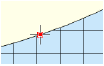
Quando a opção Atrair à Grade estiver ativada, o SmartCursor será atraído para os pontos definidos na grade de atração. Por exemplo: se a grade estiver definida para 1", o cursor será "atraído" para cada polegada quando ele se mover por sobre a grade. Ao criar uma linha, os pontos inicial e final da linha serão atraídos à grade (se nenhuma outra atração tiver sido ativada). A opção Atrair à Grade é a única que não oferece nenhuma dica visual. Se ela estiver ativada, o cursor sempre estará atraído à grade, a menos que outra atração tenha sido ativada e se sobreponha a ela.

Quando Atrair à Grade está ativo, o plano de trabalho é mostrado com pontos. Estes pontos não são mostrados quando atrair a grade está desligada. Veja Appearance of the Planes.
Para definir a atração à grade:
1 Clique na ferramenta
2 Clique
em Organizar > Ajustes do SmartCursor, ou dê um duplo clique na opção
Atrair à Gradd na paleta de Atrações.
A janela de diálogo Ajustes do SmartCursor é exibida. Na aba Grade, especifique
as opções para a grade de referência e para a grade de atração.
► Clique para exibir/ocultar os parâmetros.
|
Clique aqui para uma dica em vídeo sobre este tópico (requer acesso à internet) |
~~~~~~~~~~~~~~~~~~~~~~~~~
Ferramenta |
Conjunto de Ferramentas |
|---|---|
Atrair ao Objeto
|
Paleta de Atração |
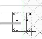
Quando a opção Atrair ao Objeto estiver ativada o SmartCursor encontra partes específicas de um objeto, como cantos, extremos, pontos médios ou os centros de objetos 2D e os cantos de arcos, bem como malhas, extrusões, varreduras, esferas, polígonos 3D, faces planas em 3D e paredes, pisos, telhados, águas de telhados, loci e colunas. As dicas são exibidas próximas ao cursor para que você possa identificar a localização.
Para definir a atração aos objetos:
1 Clique na ferramenta
2
Clique
em Organizar > Ajustes do SmartCursor, ou dê um duplo clique na opção
Atrair ao Objeto na paleta de Atrações.
A janela de diálogo Ajustes do SmartCursor é exibida. Na aba Objeto, especifique
as opções para a Atração aos Objetos.
► Clique para exibir/ocultar os parâmetros.
|
Clique aqui para uma dica em vídeo sobre este tópico (requer acesso à internet) |
~~~~~~~~~~~~~~~~~~~~~~~~~
Ferramenta |
Conjunto de Ferramentas |
|---|---|
Atrair ao Ângulo
|
Paleta de Atração |
Dois pontos definem um ângulo; o ângulo de atração aplica-se somente ao segundo ponto em um segmento de feedback de dois pontos, como quando se desenha uma linha ou um polígono. Ao atrair para ângulos, o SmartCursor localiza os ângulos especificados e por padrão localiza também os ângulos relativos aos eixos horizontal e vertical. O ângulo de atração também pode detectar um ângulo de rotação do plano (exige o Design Series); os itens criados ao longo deste ângulo, quando exibidos em uma vista de planta rotacionada, aparecem na horizontal quando estão em uma exibição de coordenadas globais não rotacionada.
Para definir a atração ao ângulo:
1 Clique na ferramenta
1. Clique em Organizar > Ajustes do SmartCursor, ou dê um duplo clique na opção Atração Angular na paleta de Atrações.
A janela de diálogo Ajustes do SmartCursor é exibida. Na aba Ângulo, especifique as configurações para a atração ao ângulo.
► Clique para exibir/ocultar os parâmetros.
Segurar a tecla Shift ao desenhar faz com que o SmartCursor selecione o ângulo de atração mais próximo.
|
Clique aqui para uma dica em vídeo sobre este tópico (requer acesso à internet) |
~~~~~~~~~~~~~~~~~~~~~~~~~
Ferramenta |
Conjunto de Ferramentas |
|---|---|
Ponto Referencial
|
Paleta de Atração |
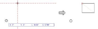
Quando a atração aos pontos referenciais estiver ativada, você poderá armazenar temporariamente um ponto onde o cursor parou por alguns segundos ou onde uma tecla de atalho foi pressionada. Assim que o Ponto Referencial for definido, você poderá alinhá-lo horizontalmente, verticalmente ou a um ângulo específico usando as linhas de extensão e as dicas do SmartCursor.
Para definir um Ponto Referencial, deixe o cursor sobre o ponto de um objeto por alguns segundos ou pressione a tecla T. Uma caixa é exibida indicando que o Ponto Referencial foi definido.
Um Ponto Referencial especial chamado de datum pode ser usado para temporariamente definir uma nova origem para fins de atração e medição. O datum não precisa estar em um objeto e pode ser colocado em qualquer lugar. Quando um datum é usado, todas as medições ao longo dos eixos X e Y são feitas a partir deste ponto, ao invés da origem do desenho, até que o datum seja movido ou desativado. Quando um dado é criado, A barra de dados mostra coordenadas relativas ao dado, usando o ponto do dado como origem. Se um dado é definido antes de mover um objeto com a ferramenta de seleção, A localização do objeto e o angulo serão medidos relativos ao dado inserido.
Para definir um datum, deixe o cursor parado por alguns segundos ou pressione a tecla G. O datum é exibido como um pequeno círculo no ponto escolhido. Veja Barra de Dados e Lista de Opções Editar Grupo para ativar a barra de Dados Flutuante automaticamente após um dado ser definido.
O SmartCursor se lembra de até três pontos referenciais, a partir do qual os pontos mais antigos são apagados. Você pode remover um Ponto Referencial deixando o cursor parado ou pressionando a tecla de atalho novamente sobre o ponto.
Se você pressionar a tecla Esc todos os pontos referenciais serão removidos.
Deve-se ativar qualquer opção de atração para que seja possível localizar pontos referenciais, e por isso recomendamos que pelo menos a opção Atrair ao Objeto esteja selecionada.
Para definir o Ponto Referencial:
1 Clique na ferramenta.
1. Clique em Organizar > Ajustes do SmartCursor, ou dê um duplo clique na opção Pontos Referenciais na paleta de Atrações.
2 A janela de diálogo Ajustes do SmartCursor é exibida. Na aba Ponto Referencial, especifique as opções para a atração ao Ponto Referencial.
► Clique para exibir/ocultar os parâmetros.
A aparência dos pontos referenciais pode ser alterada; veja Configurando as Dicas Interativas de Tela. A tecla de atalho para os pontos referenciais e para o datum pode ser definida; veja Modifying Special Shortcuts.
|
Clique aqui para uma dica em vídeo sobre este tópico (requer acesso à internet) |
~~~~~~~~~~~~~~~~~~~~~~~~~
Ferramenta |
Conjunto de Ferramentas |
|---|---|
Borda Referencial
|
Paleta de Atração |
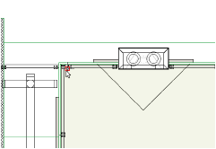
Quando a Atração à Borda Referencial estiver ativada, o SmartCursor procurará pontos em um canto 2D especificado, ou em uma certa distância a partir deles. Os cantos da geometria 2D, bem como os segmentos de curva de arcos e polilinhas, podem ser usados como Bordas Referenciais. Assim que a Borda Referencial for definida, você poderá alinhá-la horizontalmente, verticalmente ou em um ângulo específico através das linhas de extensão e das dicas do SmartCursor. Uma Borda Referencial também fornece atração a um ponto em um canto sem que seja necessário ativar a opção de atração ao Ponto Mais Próximo em Borda.
Para definir uma Borda Referencial, deixe o cursor sobre o canto de um objeto 2D por alguns segundos ou pressione a tecla T quando estiver sobre o canto. Linhas de extensão pontilhadas irão indicar que a Borda Referencial foi definida.
Até duas Bordas Referenciais podem ser definidas, e as bordas anteriores serão excluídas. Uma Borda Referencial pode ser excluída ao deixar o cursor sobre o canto por alguns segundos ou pressionando a tecla T quando estiver sobre o canto.
Para definir a atração à Bordas Referenciais:
1 Clique na Ferramenta.
2 Clique em Organizar > Ajustes do SmartCursor, ou dê um duplo clique na opção Bordas Referenciais na paleta de Atrações.
A janela de diálogo Ajustes do SmartCursor é exibida. Na aba Bordas Referenciais, especifique as opções para a atração à Borda Referencial.
► Clique para exibir/ocultar os parâmetros.
A aparência das Bordas Referenciais pode ser alterada; veja Configurando as Dicas Interativas de Tela. A tecla de atalho para as Bordas Referenciais pode ser definida; veja Modifying Special Shortcuts.
~~~~~~~~~~~~~~~~~~~~~~~~~
Ferramenta |
Conjunto de Ferramentas |
|---|---|
Distância da Atração
|
Paleta de Atração |
Quando a opção Distância de Atração estiver ativada, o SmartCursor procurará por pontos em uma distância selecionada ao longo de uma linha, de uma curva, dos cantos de um polígono, das paredes retas e de outros objetos lineares

Para definir a distância de atração:
1 Clique na Ferramenta.
2 Clique em Organizar > Ajustes do SmartCursor, ou dê um duplo clique na opção Distância na paleta de Atrações.
A janela de diálogo Ajustes do SmartCursor é exibida. Na aba Distância, especifique as opções para atração à distância.
3 Defina a distância usando uma fração, uma porcentagem ou uma distância dimensional. Clique em Múltiplas Divisões para repetir os pontos de atração ao longo de uma linha. Por exemplo: o SmartCursor pode ser atraído a cada quarto de polegada ou a cada 1/8 do comprimento da linha.
O SmartCursor mede a partir de cada extremo até o centro da linha. Se uma linha possui 10 unidades de tamanho e a distância está definida para 6 unidades, esta distância não será encontrada pois ela é maior do que metade da linha. Da mesma forma, qualquer fração superior a 1/2 do tamanho do objeto ou menor que 0 não pode ser utilizada.
~~~~~~~~~~~~~~~~~~~~~~~~~
Ferramenta |
Conjunto de Ferramentas |
|---|---|
Atrair à Interseção
|
Paleta de Atração |
Quando a Atração à Interseção estiver ativada, o SmartCursor irá localizar a interseção entre dois objetos ou entre as partes de um objeto, ou entre as partes dos objetos e as linhas de extensão ou as Bordas Referenciais.

Para ativar a atração à intersecção:
Clique na opção Atrair à Interseção na paleta de Atrações. Não é necessário configurar nenhum parâmetro.
~~~~~~~~~~~~~~~~~~~~~~~~~
Ferramenta |
Conjunto de Ferramentas |
|---|---|
Atração Tangencial
|
Paleta de Atração |
A opção Atração Tangencial usa o SmartCursor para localizar tangentes em uma geometria de arco circular ao desenhar.
As tangentes não podem ser localizadas em arcos de um quarto de círculo.
Para ativar a atração à tangente:
Clique na opção Atração Tangencial na paleta de Atrações. Não é necessário configurar nenhum parâmetro.

Segure a tecla Option (Macintosh) ou Alt (Windows) para alternar para a tangente do lado oposto ao objeto.
|
Clique aqui para uma dica em vídeo sobre este tópico (requer acesso à internet) |
~~~~~~~~~~~~~~~~~~~~~~~~~
Ferramenta |
Conjunto de Ferramentas |
|---|---|
Atração ao Plano de Trabalho
|
Paleta de Atração |
Quando a opção Atração ao Plano de Trabalho estiver ativada, o SmartCursor será atraído ou se projetará a qualquer ponto que não esteja no plano de trabalho ou descendo até seu ponto sombreado no plano de trabalho. Se você clicar em um objeto 3D, o snap é projetado para um ponto no plano de trabalho, forçando o snap ao plano de trabalho. Esse encaixe substitui temporariamente outro encaixe que pode interferir na capacidade de restringir o encaixe ao plano de trabalho. Isso é útil para desenhar objetos 3D encaixados no plano de trabalho e mover objetos 3D alinhados ao plano de trabalho.
Para ativar a atração ao Plano de Trabalho:
Clique na ferramenta. Nenhum parâmetro é necessário.
Clique na opção Atração ao Plano de Trabalho na paleta de Atrações. Não é necessário configurar nenhum parâmetro.

|
Clique aqui para uma dica em vídeo sobre este tópico (requer acesso à internet) |
~~~~~~~~~~~~~~~~~~~~~~~~~
Diversas configurações e opções são combinadas para facilitar o desenho com atração. Diversos tipos de atração e indicadores o ajudam com essa tarefa. A Lupa de Atração aproxima temporariamente o desenho próximo ao cursor para que você possa atingir o ponto de atração em um desenho complexo.
A atração é usada com a linha de prévia do segmento de feedback que é exibida por diversas ferramentas ao desenhar. Por exemplo: ao desenhar uma linha você pode querer que ela seja vertical e que esteja alinhada com um ponto em seu desenho. Para fazer isso, defina um Ponto Referencial (com Linhas de Extensão) sobre o ponto onde você deseja alinhar. A opção Atrair ao Ângulo deve estar ativada (pois ele é atraído pela vertical) junto com a opção Atrair ao Ponto Referencial. O segmento de feedback da linha é atraído para a vertical e para o Ponto Referencial, e um segundo clique finaliza o desenho da linha da forma desejada.

Algumas áreas no Vectorworks controlam os diferentes aspectos da atração.
Função |
Localização/Descrição |
|---|---|
Ativar ou desativar as opções de atração |
Paleta de Atrações |
Ativar ou desativar parâmetros individuais de atração |
Janela de diálogo Ajustes do SmartCursor |
Alterar a aparência dos pontos de atração e dos indicadores |
Caixa de diálogo Configurações Interativas de Aparência; Configurando as Dicas Interativas de Tela |
Ativa ou desativa o retângulo de atração, o retângulo de seleção e as dicas de aquisição |
Aba Interatividade das Preferências do Vectorworks |
Altera a aparência do retângulo de atração e do retângulo de seleção. |
Aba Interatividade das Preferências do Vectorworks |
Salvar opções de atração em um VectorScript |
Comando Personalizar Ferramentas/Atributos; Creating Custom Tool/Attribute Scripts |
Alterar as teclas de atalho de atração |
Aba Teclas no Editor de Interface; Modifying Special Shortcuts |
Atraindo a objetos em outras camadas, classes ou camadas definidas como meio tom |
Comandos Opções de Classes e Camadas; Setting Global Visibility with Class and Design Layer Options |
~~~~~~~~~~~~~~~~~~~~~~~~~
Existem vários tipos de pontos de atração. Use-os em conjunto com as configurações na paleta de Atrações, na janela de diálogo Ajustes do SmartCursor, na janela de diálogo Aparência das Dicas Interativas, na aba Interativo e nas Preferências do Vectorworks para definir a atração e a aparência de acordo com a tarefa desejada. Além dos pontos de atração, outros elementos interativos o ajudarão com a atração.
• Pontos de atração disponíveis
Os pontos de atração disponíveis serão exibidos próximo ao cursor dentro do raio de atração para indicar que um ponto de atração está próximo.

• Pontos de atração especiais
Os pontos de atração especiais serão exibidos na área geral do cursor para indicar que o ponto médio, o centro, o ponto ao longo da linha e/ou os pontos de atração da tangente estão próximos. Os pontos de atração que poderão ser vistos dependerão das opções de atração ativadas na janela de diálogo Ajustes do SmartCursor e da Paleta de Atrações.

• Ponto de atração atual
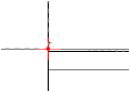
O ponto de atração atual indica que o SmartCursor foi atraído.
O ponto de atração atual é representado na cor preta quando em 2D. Quando em 3D, é representado pelas cores vermelha (eixo X), verde (eixo Y) e azul (eixo Z). A orientação da representação em 3D é relativa ao plano de trabalho. As linhas tracejadas indicam os eixos negativos.

• Ponto de atração obtido
Ao desenhar com uma ferramenta como a Ferramenta Linha, o primeiro clique com a ferramenta em um ponto de atração atual faz com que ele se torne um ponto de atração obtido. O ponto de atração obtido é exibido somente por alguns segundos para indicar que o clique foi atraído.
• Ponto referencial
Quando a Atração ao Ponto Referencial é ativada, até três Pontos Referenciais podem ser definidos de uma vez; veja Atrair aos Pontos Referenciais. Um Ponto Referencial é exibido como um retângulo vermelho por padrão. Se as Linhas de Extensão estiverem ativadas, a linha de extensão para o ponto referencial será exibida como uma linha tracejada. Um datum é um tipo especial de Ponto Referencial que é considerado como um dos três pontos.

• Destaque de objeto atraído
O objeto a partir do qual os pontos de atração são criados é destacado com uma linha tracejada. Isto garante que os pontos de atração corretos serão obtidos em um desenho complexo.
• Região de seleção e de atração do SmartCursor
Duas áreas em torno do cursor ajudam você a desenhar a região de seleção e a região de atração.

O retângulo de seleção mostra a área onde a geometria do objeto pode ser selecionada ou reconhecida por uma ferramenta que seleciona ou clica em objetos (como a Ferramenta de Seleção ou o Conta Gotas). O retângulo de atração indica a área de onde a atração será obtida. A atração atual é obtida a partir de todas as atrações disponíveis dentro da caixa de atração.
O tamanho e a visibilidade dos retângulos de seleção e de atração pode ser ajustado, e estes indicadores podem ser ativados, na aba Interativo das Preferências do Vectorworks.
• Indicador
de ponto de pressão nas proximidades
Em áreas congestionadas do desenho, um ícone é exibido à esquerda do texto
de sugestão do SmartCursor para indicar a existência de pontos de acesso
próximos. Aumente o zoom ou use a lupa instantânea para obter uma visualização
detalhada e garantir que o ponto de encaixe correto esteja selecionado.

• Master snap points
In congested areas of the drawing, when there are many object snap points within the snap box, enable the master snap point display in the Atrair aos Objetos settings. The master snap point takes priority over other snap points, for quickly obtaining the desired snap point during operations like dimensioning or moving objects.
The master snap point location is a property of an object and is primarily intended for use in Top/Plan view. Shapes like rectangles, arcs, circles, polylines, have master snap points at places where they are logically expected, such as corners, centers, or end points. The insertion point is the master snap point location for many of the Vectorworks default content resources and parametric objects; path-based parametric objects inherit the master snap point location from the path object. Master snap points are located on roof and bearing line corners. For curtain walls, the master snap points are located on the center of the frames. Windows and doors have snap points on each end and in the center.

Certain objects allow the master snap point location to be specifically defined. Walls and slabs with components can have master snap points located on the component sides; see Defining Components for New Walls and Creating Slab Components. A locus is used to define the master snap point location for symbols and groups; see Editando Definições de Símbolo.

• Dicas de aquisição
As dicas de aquisição mostram os pontos de atração em potencial próximos ao cursor e que podem ser adquiridos. Eles indicam que um Ponto Referencial, uma Borda Referencial ou uma Trava Vetorial podem ser adquiridas.
Dicas de Aquisição |
Aparência |
|---|---|
Ponto referencial |
|
Borda referencial |
|
Trava vetorial |
|

Ativa as dicas de aquisição da aba Interativa nas preferências do Vectorworks.
• Indicadores de Alinhamento
Indicadores de eixos e planos coloridos (cores claras) oferecem dicas que ajudam determinar se o cursor está alinhado com um eixo (2D) ou com um eixo e/ou plano (3D). A cor da indicação coincide com a cor do eixo (vermelho para X, verde para Y e azul para Z) para ajudar na identificação quando o cursor está alinhado com um eixo ou um plano.

~~~~~~~~~~~~~~~~~~~~~~~~~
Uma linha de extensão criada a partir de um Ponto Referencial indica um vetor ou direção. Este vetor pode ser travado para facilitar o desenho e a movimentação de objetos, pois o SmartCursor permanece travado ao vetor e serve como guia para atração ao longo do vetor.
Para criar uma trava vetorial:
1. Selecione a ferramenta de desenho, um objeto a ser movido ou outra operação que exija uma trava vetorial.
É útil exibir as dicas de aquisição, que são exibidas quando uma trava vetorial pode ser definida. Esta é uma preferência interativa do Vectorworks; veja Aba Interatividade.
2.Durante a operação o segmento de feedback indica a direção do vetor e a dica de aquisição no cursor indica que uma trava vetorial pode ser definida. Uma trava vetorial pode ser definida ao longo de uma linha de extensão de um Ponto Referencial. Quando o cursor se move ao longo da linha de extensão, a dica de atração de trava é exibida indicando que uma trava vetorial pode ser definida.
3. Pressione a tecla T para criar uma trava de vetor na direção da linha de extensão, ou pressione a tecla G para definir o bloqueio do vetor em relação a um dado, usando a barra de dados.
A trava de vetor é exibida. A aparência das travas de vetor pode ser alterada como descrito em Configurando as Dicas Interativas de Tela.

4. O SmartCursor se trava ao vetor e a operação é atraída ao longo da direção desejada.

A Barra de Dados pode criar uma trava vetorial ao longo de uma direção indicada. Informe os dados na Barra de Dados como descrito na seção Usando a Barra de Dados. Uma trava vetorial é exibida, e o SmartCursor só é atraído aos pontos da linha travada.
~~~~~~~~~~~~~~~~~~~~~~~~~
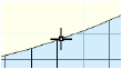
Em um desenho complexo pode ser difícil atingir o ponto de atração desejado. A Lupa de Atração aproxima temporariamente o desenho para que você possa atingir o ponto de atração. Nesta exibição ampliada, os pontos de atração próximos ao cursor ficam mais fáceis de se enxergar.
A Lupa de Atração não pretende incluir a navegação dentro da Janela da Lupa. Ela é apenas uma forma fácil de se atingir pontos de atração e retornar rapidamente ao desenho.
Para usar a Lupa de Atração:
1 Mova o cursor para a área onde você deseja ter a atração mas é difícil de conseguí-la.
2.Pressione a tecla Z.
A caixa da Lupa de Atração é aberta, exibindo ampliada a região próxima ao cursor. Dentro da caixa da Lupa de Atração, mova o cursor para localizar o ponto desejado. Se a Lupa de Atração não oferecer ampliação suficiente, pressione a tecla Z novamente.
A opção Aproximar Espessuras na Lupa de Atração determina como o desenho será exibido dentro da Lupa de Atração. Veja Atração Geral para alterar essa configuração.
3. Clique no ponto de atração desejado. A janela da Lupa de Atração é fechada automaticamente e retorna-se ao desenho.
Pressione Esc para sair da Lupa de Atração sem clicar, ou clique fora da lupa para fechar.
|
Clique aqui para uma dica em vídeo sobre este tópico (requer acesso à internet) |
~~~~~~~~~~~~~~~~~~~~~~~~~
As dicas do SmartCursor e seu significado estão listadas abaixo. Em vários casos, duas dicas são usadas juntas para indicar que duas restrições foram usadas. Por exemplo, a sugestão Alinhar H/Ângulo significa que o ponto localizado é alinhado tanto horizontalmente ao ponto indicado como também está restrito a um ângulo.
Algumas dicas requerem que um primeiro ponto já tenha sido encontrado, e um segundo ponto esteja sendo procurado. Esses dois pontos formam uma linha chamada "segmento de feedback". Este segmento está a um ângulo e a uma distância que o SmartCursor usa para algumas de suas atrações.
 Quando outros pontos de snap
estão próximos, um ícone é exibido à esquerda do texto do SmartCursor
cue para alertá-lo. Aumente o zoom ou use a lupa para uma visão suficientemente
próxima para selecionar o ponto de encaixe desejado.
Quando outros pontos de snap
estão próximos, um ícone é exibido à esquerda do texto do SmartCursor
cue para alertá-lo. Aumente o zoom ou use a lupa para uma visão suficientemente
próxima para selecionar o ponto de encaixe desejado.
No caso de uma linha, o segmento de feedback corresponde a linha que está sendo criada. Entretanto, para outros objetos, a imagem interativa que você vê na tela não representa o segmento de feedback. O SmartCursor sempre funciona no segmento de feedback criado do primeiro para o segundo ponto (para polígonos, do ponto anterior para o ponto atual).
Dica |
Descrição |
|---|---|
Atração Angular |
|
Alt |
Segmento está paralelo ao ângulo alternativo. |
Alt 90° |
Segmento está perpendicular ao ângulo alternativo. |
Delta Angular |
O segmento desenhado está em um ângulo específico a partir da grade rotacionada. |
Horizontal |
Segmento desenhado está na horizontal. |
Paralelo |
Segmento está paralelo a um objeto. |
Perpendicular |
Segmento está perpendicular a um objeto. |
Rotação de Plano (requer o Design Series) |
Segmento alinhado com o plano rotacionado. |
Simétrico |
Segmento está esboçando a criação de um quadrado ou círculo. |
Vertical |
Segmento está na vertical. |
X |
Segmento está alinhado com o eixo X |
Y |
Segmento está alinhado com o eixo Y |
Z |
Segmento está alinhado com o eixo Z , ou o ponto está alinhado na direção Z com o ponto referencial. |
X’ |
Segmento está alinhado com o eixo X da grade rotacionada |
Y’ |
Segmento está alinhado com o eixo Y da grade rotacionada |
Z’ |
Segmento está alinhado com o eixo Z da grade rotacionada, ou o ponto está alinhado na direção Z da grade rotacionada com o ponto referencial. |
Ponto Referencial |
|
-------------- |
A linha de extensão é usada para todos os pontos lógicos, exceto o Datum. |
Alin |
Segmento desenhado está perpendicular ao segmento da posição atual do cursor até o ponto referencial. |
Alin H |
Ponto está alinhado horizontalmente com um ponto referencial. |
Alin V |
Ponto está alinhado verticalmente com um ponto referencial. |
Alin X |
Ponto está alinhado com a coordenada X do ponto referencial |
Alin Y |
Ponto está alinhado com a coordenada Y do ponto referencial |
Alin Z |
Ponto está alinhado com a coordenada Z do ponto referencial |
Alin X’ |
Ponto está alinhado com a coordenada X do ponto referencial, no espaço da grade rotacionada. |
Alin Y’ |
Ponto está alinhado com a coordenada Y do ponto referencial, no espaço da grade rotacionada. |
Alin Z’ |
Ponto está alinhado com a coordenada Z do ponto referencial, no espaço da grade rotacionada. |
Alin. Borda |
Ponto está alinhado à Borda Referencial. |
Alin. Borda 90° |
Ponto está alinhado perpendicularmente à Borda Referencial |
Alin. Alt |
Ponto está alinhado ao sistema de coordenadas alternativo. |
Alin. Alt 90° |
Ponto está alinhado perpendicularmente ao sistema de coordenadas alternativo. |
Datum |
O ponto é o Datum atual do desenho. |
O |
Círculo ao redor do Datum. |
Plano de Trabalho |
Ponto sobre o plano da grade. |
Atrair à Distância |
|
Dist |
2D - O ponto é especificado a uma distância ao longo da linha 3D - O ponto é especificado a uma distância ao longo da linha a partir do ponto final de uma curva NURBS, polígono 3D ou borda de um objeto sólido |
Barra de Dados |
|
-------------- |
Linha de extensão usada para valores fixados de X e Y. |
Ângulo |
O segmento está restrito a um valor de ângulo. |
Comprimento |
O segmento está restrito a um valor de comprimento fixado na Barra de Dados. |
Atrair a Objetos |
|
Arco |
O cursor está em um vértice de um segmento de uma polilinha por Arcos. |
Centro de Arco |
O cursor está sobre o ponto central de um arco. |
Fim de Arco |
O cursor está no extremo de um segmento de arco. |
Bézier |
O cursor está em um vértice de um segmento de uma polilinha Bézier. |
Centro Inferior |
O cursor está no centro inferior de um retângulo ou grupo. |
Esquerdo Inferior |
O cursor está colocado diretamente sobre esta parte dos limites de contorno do objeto. |
Direito Inferior |
O cursor está colocado diretamente sobre esta parte dos limites de contorno do objeto. |
Centro |
2D - O cursor está posicionado diretamente sobre esta parte do contorno limite do objeto 3D - O cursor está no ponto médio da borda de um sólido, curva NURBS, polígono 3D ou centro de uma curva NURBS circular |
Centro Esquerdo |
O cursor está colocado diretamente sobre esta parte dos limites de contorno do objeto |
Centro Direito |
O cursor está colocado diretamente sobre esta parte dos limites de contorno do objeto |
Canto |
O Cursor está sobre o ponto de canto de uma polilinha. |
Extremo |
O Cursor está sobre o extremo (final) de uma borda de um objeto. |
Encaixar |
O cursor está em um vértice de um segmento de uma polilinha Cúbica.nt |
Origem Interna |
O cursor está sobre a origem interna |
Ponto de Inserção |
O Cursor está sobre a origem de um símbolo, objeto paramétrico ou objeto texto; para cotas, o cursor está sobre um dos pontos referenciais. |
Luz |
O Cursor está sobre uma luz |
Locus |
O cursor está sobre um locus |
Locus 3D |
O Cursor está sobre um Locus 3D |
Ponto Médio |
O Cursor está sobre a metade de uma borda do objeto. |
Objeto |
2D - O ponto está na borda do objeto 3D - O ponto está em qualquer ponto não específico ao longo da borda de um sólido ou curva NURBS; um alto ponto de canto quando a restrição Atrair à Borda estiver desselecionada |
Página |
O cursor está sobre o contorno da página |
Centro Inferior da Página |
O Cursor está sobre o centro inferior do contorno da página |
Esquerda Inferior da Página |
O Cursor está sobre a esquerda inferior do contorno da página |
Direita Inferior da Página |
O Cursor está sobre a direita inferior do contorno da página |
Centro da Página |
O Cursor está sobre o centro da página |
Centro Esquerdo da Página |
O Cursor está sobre o centro esquerdo do contorno da página |
Centro Direito da Página |
O Cursor está sobre o centro direito do contorno da página |
Centro Superior da Página |
O Cursor está sobre o centro superior do contorno da página |
Topo Esquerdo da Página |
O Cursor está sobre o topo esquerdo do contorno da página |
Topo Direito da Página |
O Cursor está sobre topo direito do contorno da página |
Ponto |
2D - O ponto está em um objeto 3D - O ponto está em um dos vértices de um sólido, o ponto de controle de uma curva NURBS, o ponto de controle de uma superfície NURBS ou ponto de interpolação da curva NURBS |
Centro Superior |
O cursor está colocado diretamente sobre esta parte dos limites de contorno do objeto. |
Esquerdo Superior |
O cursor está colocado diretamente sobre esta parte dos limites de contorno do objeto. |
Direito Superior |
O cursor está colocado diretamente sobre esta parte dos limites de contorno do objeto. |
Borda Referencial |
|
Bissetriz |
O cursor está sobre a linha bissetriz entre duas bordas ativadas. |
Borda |
O segmento está paralelo a uma borda referencial, ou o cursor está sobre a borda entre dois pontos referenciais. |
Borda 90° |
O segmento está perpendicular a uma borda. |
Deslocamento |
O cursor está a uma distância pré-determinada de uma borda. |
Borda Referencial |
O ponto está em uma borda referencial, mas não no próprio objeto. |
Atrair à tangente |
|
Tangente |
O segmento está tangente a um arco |
Tangente/Tangente |
O segmento está tangente a dois arcos |
~~~~~~~~~~~~~~~~~~~~~~~~~
Objetos 2D podem ser criados como objetos de plano de tela ou como objetos (planares) de plano da camada, dependendo do modo de seleção de planos.
• O plano de tela coincide com o plano da tela do monitor, perpendicular a direção de visualização. Objetos 2D desenhados no plano de tela "flutuam" nas vistas 3D
• Os objetos planares, no entanto, existem no espaço 3D; um objeto 2D planar é mostrado associado ao plano da camada que o contém, mantendo assim sua relação com o modelo 3D em vistas 3D.

Por padrão, os objetos são criados como objetos planos. Eles são exibidos em aramado com seus atributos gráficos no plano de camada em vistas que não sejam a Topo/Planta, e se tornarão parte do modelo 3D.
Os objetos 2D podem ser criados e editados em qualquer plano e em qualquer vista. A edição ocorre no contexto planar do plano do objeto. Ao realizar operações em mais de um objeto planar em uma vista 3D, estes objetos devem ser co-planares.
Duplo-clique em um objeto planar para definir o plano de trabalho como sendo o plano onde o objeto foi criado.
A ferramenta dividir, bem como os comandos Modificar > Rotacionar > Rotacionar, Rotacionar à Esquerda, Rotacionar à Direita e Inverter, operam somente no plano de tela.
A maioria dos objetos 2D podem funcionar corretamente como planar, mas alguns objetos funcionam melhor como objetos de plano de tela. Por exemplo: todos os elementos em camadas de folha estão, por definição, no plano de tela. Os objetos criados como objetos de recorte para viewports são colocados automaticamente no plano de tela. Além disso, ao criar símbolos híbridos especiais, o componente 2D do símbolo deve ser criado no plano de tela, para que o símbolo tenha uma representação quando for visualizado na vista Topo/Planta.
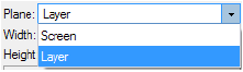
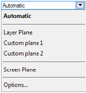
A lista de Planos Ativos, localizada na Barra de Visualização, define o plano ativo no momento e determina se os objetos 2D são criados como objetos plano ou plano de tela. Os planos disponíveis dependem da vista do desenho, da ferramenta atual, da presença de planos de trabalho nomeados e das opções do modo de plano.
• Para criar objetos planos, selecionar Plano da Camada da lista de Planos Ativos.
• Para criar objetos de plano de tela, selecionar Plano de Tela.
• Para criar objetos planos no plano de trabalho automático, selecionar Automático como descrito em Conceito: O Plano de Trabalho Automático.
O modo plano selecionado permanece em vigor até a próxima vez que for alterado.

Um objeto 2D existente selecionado, desenhado no modo de plano de tela, pode ser alternado para a camada (plano) e vice-versa. A lista de Planos Ativos na guia Forma da Paleta Info de Objetos alterna a propriedade de plano de objetos 2D existentes selecionados.
|
Clique aqui para uma dica em vídeo sobre este tópico (requer acesso à internet) |
Dependendo do seu fluxo de trabalho e das configurações de preferências do Documento, as opções disponíveis na lista de Planos Ativos podem ser restritas, para nunca mostrar o plano da camada ou nunca mostrar o plano da tela.
Em uma vista 3D, e quando o plano de tela não for o plano ativo, os objetos planos como círculos, retângulos, retângulos com cantos arredondados, ovais, arcos, polilinhas e polígonos podem ser extrudados imediatamente após a criação se o modo Empurrar/Puxar na barra de ferramentas estiver ativada. A alternância de modo é aplicada a todas as ferramentas planas; se o modo for ativado para uma das ferramentas, ele será ativado em todas as ferramentas. Com isto você pode rapida e facilmente criar objetos 3D a partir de objetos planos, apenas movendo o cursor ou informando a distância na barra de dados.

Quando o modo plano de trabalho automático estiver ativado e o modo Empurrar/Puxar for usado em um objeto que ofereça suporte a operações sólidas, pressione a tecla Option (Macintosh) ou Alt (Windows) e puxe para fazer uma adição sólida ou empurre para fazer uma subtração sólida.
O modo Empurrar/Puxar dos objetos planos trabalha de forma diferente após a criação do objeto. Se o objeto não estiver selecionado, ele poderá ser extrudado posteriormente usando a ferramenta Empurrar/Puxar; veja Modelagem Direta. Em algumas situações o modo Empurrar/Puxar precisará ser desativado, como por exemplo na criação de objetos planos seguidos.
|
Clique aqui para uma dica em vídeo sobre este tópico (requer acesso à internet) |
~~~~~~~~~~~~~~~~~~~~~~~~~
The working plane is an important concept for working in 3D. This section covers all aspects of the working plane, including setting, manipulating, and saving the working plane position.
~~~~~~~~~~~~~~~~~~~~~~~~~
Every Vectorworks layer has a 3D plane associated with it. When a layer is active, this 3D plane is called the active layer plane. The active layer plane provides a constant visual and logical reference and is fixed in relation to the objects in the layer. In an architectural sense, the active layer plane is like the floor of a building; it is sometimes referred to as the ground plane.
Every Vectorworks drawing also has a working plane. The location of the working plane defaults to that of the active layer plane, and it is not seen. However, when working and modeling in 3D, the orientation of the working plane can be changed, and its positions saved. The working plane can be moved, aligned to different objects or surfaces, and rotated, unlike the active layer plane, which remains constant at the internal drawing center.
Working in 3D requires the cursor to snap to a 3D location. When no other 3D snap is active (the cursor is not snapping to 3D geometry), the cursor still needs to snap to a 3D location; this location is the 3D plane called the working plane.

Every object created in the drawing is placed in relation to the active layer plane for that layer, whether it is placed directly on that plane or placed above or below it. The working plane helps to easily create and position objects in 3D space. It allows you to draw while in an isometric view and position objects exactly where they are needed. When you change the location of the working plane, the active layer plane remains displayed, providing a constant frame of reference while you adjust the working plane.

For example, for a drawing of a complex machine, with numerous gears, cams, rollers, and other parts that intersect on multiple planes, the working plane can be changed to different locations and angles in relation to the active layer plane. Creating or locating objects according to the working plane allows highly accurate positioning of the objects in 3D space.

Hybrid symbols can only be inserted on a working plane that is parallel to the active layer plane. When inserting a hybrid symbol, if the working plane is not parallel to the active layer plane, the working plane is moved to, and aligned with, the active layer plane.
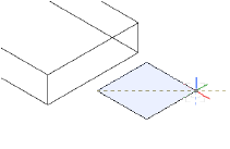
In addition, some tools require a vector or plane. The 3D viewing tools can use the working plane to define their center and/or axis of rotation, while the Mirror tool can mirror the selected 3D objects across the working plane. The location of 3D tools in 3D space is taken from the point on the working plane directly behind the cursor, or from a snap point if they are snapped to an object.
To assist with drawing in 3D with certain drawing tools, an automatic working plane appears on suitable object surfaces as the cursor moves over drawing objects with the tool selected. The automatic working plane is a temporary working plane that does not need to be explicitly set; see Conceito: O Plano de Trabalho Automático.

If there is no suitable surface under the cursor, the automatic working plane aligns to the layer plane.
When the automatic working plane is in effect, Automatic displays in the Active Planes list located on the View bar.
~~~~~~~~~~~~~~~~~~~~~~~~~
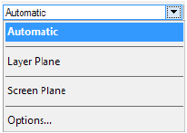
On the View bar, the Active Planes list displays the currently active plane, and also allows other active planes to be selected. The available planes depend on the drawing view, current tool, presence of named working planes, and plane mode options.
Plane |
Description |
|---|---|
Automatic |
The active working plane changes as the cursor moves over the drawing area in a 3D view. The automatic plane is a temporary working plane that does not need to be set; over suitable surfaces and with certain drawing tools, the automatic plane is planar to the surface. Otherwise, the automatic plane aligns to the layer plane. |
Layer Plane |
The active working plane is planar to the current plane of the active layer |
Custom Plane |
The active working plane is planar to a saved working plane position; selecting a working plane cancels the automatic working plane. |
Screen Plane |
The active working plane is aligned to the screen plane (planar to the computer screen) |
Screen Aligned |
The active working plane is parallel to the screen plane in the current orthographic view |
Options |
Opens the Document Preferences dialog box, for setting the plane mode options; see Preferência do Modo Plano |
~~~~~~~~~~~~~~~~~~~~~~~~~
Um plano de trabalho é um local no espaço 3D onde os objetos podem ser criados. Por padrão, o plano de trabalho e o plano da camada estão no mesmo local, mas o plano de trabalho pode ser posicionado em qualquer lugar para auxiliar no desenho de objetos.
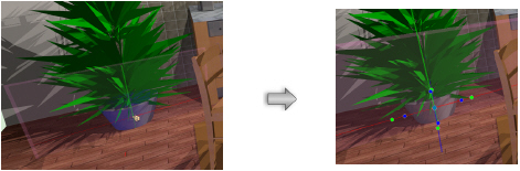
O plano de trabalho automático, quando está ligado e quando uma ferramenta de desenho típica é selecionada, sempre mostra um plano adequado para a criação de objetos, com base nas superfícies existentes no desenho. Conforme o cursor se move sobre as superfícies de desenho, o plano de trabalho automático é realçado na superfície para indicar que um objeto de desenho pode ser colocado ali e será desenhado planarmente para a superfície. “Automático” é exibido na lista Planos Ativos. Os objetos criados no plano de trabalho automático são desenhados para o plano de trabalho automático, e não no plano da camada. Isso facilita o desenho de objetos planares sem a necessidade de criar ou salvar um plano de trabalho.

Quando o cursor não está sobre uma superfície adequada enquanto está em uma visualização 3D, o plano automático padrão está em vigor. O plano de trabalho automático padrão se alinha ao plano da camada e um objeto desenhado é colocado no plano da camada.
A cor e a opacidade do plano de trabalho automático podem ser personalizadas; vejaConfigurando as Dicas Interativas de Tela.
Em alguns casos, pode ser desejável desligar o plano de trabalho automático, como ao desenhar no plano da camada ou plano da tela, ao desenhar em uma superfície oculta onde o plano automático não aparece, ou ao desenhar em um plano de trabalho específico que foi estabelecido pela ferramenta Set Working Plane. Quando você usa uma ferramenta de plano de trabalho, como a ferramenta Set Working Plane, o plano de trabalho automático é desativado. Selecione um plano diferente da lista, como um plano de trabalho salvo, ou pressione a tecla \ (barra invertida) para ativar e desativar o plano de trabalho automático. Essa chave pode ser personalizada no editor de espaço de trabalho; veja Modifying Special Shortcuts. A cor e a opacidade do plano de trabalho automático também podem ser personalizadas; veja Configurando as Dicas Interativas de Tela.
~~~~~~~~~~~~~~~~~~~~~~~~~
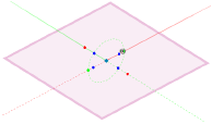
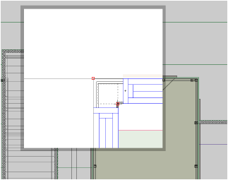
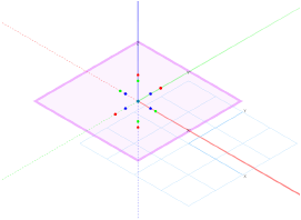
In any view other than Top/Plan, the layer plane is represented in blue; when active, it has red X and green Y axes (an option in the display preferences of the Vectorworks preference can also show the axes in Top/Plan). When the working plane and the active layer plane are located in the same position, only the active layer plane is shown. However, once the position of the working plane has been changed or directly set, it is represented on the screen as a colored frame. The color of the active layer plane and appearance of the working plane can be customized in the Vectorworks preferences; see Aba Interatividade for details.
The axis lines of both the working plane and the automatic working plane are colored red for X’, green for Y’, and blue for Z’; dashed axes represent the negative axes. In a 3D view, the axes are always visible, although they appear more transparent when they are behind rendered solid objects. The Z’ axis and all axis labels are optionally displayed by settings in the SmartCursor Settings dialog box; see Atrair à Grade.

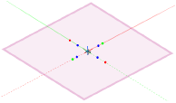
Simply click an axis with the Set Working Plane tool to select and display the working plane and its grip handles. When the working plane is selected, it displays with colored grips around each axis, as well as a move grip, for manipulating the plane.
The working plane can be moved, but not rotated, when in rotated Top/Plan view (Vectorworks Design Series required). See Rotating the Plan.
When grid snapping is enabled, the working plane displays with dots; when grid snapping is off, the dots do not display. The working plane displays slightly darker, and with a double line frame, when it is viewed from below.
When the working plane and the active layer plane are coincident, the active layer plane displays with grid lines. Otherwise, when the planes are not coincident, the grid lines do not display on the active layer plane.
Dashed gray lines represent the intersection of the active layer plane and working planes. The active layer plane does not display in a rendered view.

If the active layer plane grid lines are not visible, select Show Grid in the SmartCursor Settings dialog box (see Atrair à Grade).
~~~~~~~~~~~~~~~~~~~~~~~~~

The Set Working Plane tool is in the 3D Modeling tool set.
The Set Working Plane tool can set the location and angle of the working plane. Set the working plane to any location in 3D space.
Double-click the Set Working Plane tool to set the working plane to the layer plane. Double-click a planar object to re-activate the working plane on which it was created.
The tool has two modes:

Mode |
Description |
|---|---|
Three Point |
Defines the working plane by three 3D points, or according to the surface of a rendered object |
Planar Face |
Aligns the working plane to a planar face; or, for a NURBS curve, aligns the working plane perpendicular to that point's tangent on the curve |
Once the working plane location has been set, Custom Plane displays in the Active Planes list on the View bar. The location can be saved; see Working Plane Commands.
The working plane can be quickly set based on the automatic working plane location. Right-click on the automatic working plane, and select Set Working Plane from the context menu (or select Modify > Working Plane > Set Working Plane). The working plane is set to match the automatic working plane, and the working plane is active.

|
Clique aqui para uma dica em vídeo sobre este tópico (requer acesso à internet) |
~~~~~~~~~~~~~~~~~~~~~~~~~
Mode |
Tool |
Tool set |
|---|---|---|
Three Point |
Set Working Plane
|
3D Modeling |
The Set Working Plane tool and Align Plane tool share the same position on the tool set. Click and hold the mouse on the visible tool to open the Ferramentas Pop-out list and select the desired tool.
When you use the Three Point mode of the Set Working Plane tool, two methods are available for defining the working plane location. With the first method, you set the position and angle of the working plane by defining the origin and axes of the new working plane location. With the second method, you set the position and angle of the working plane according to a rendered object’s surface.
To set the working plane with three points:
1 In a 3D view, click the tool and mode.
2 Click to set the first point.
This becomes the origin of the working plane.
3 Click to set the second point.
This sets the working plane X’ axis.
4 Select the third point.
This sets the Y’ axis for the working plane. Once the third point is defined, the working plane location is set.

The working plane can be defined according to the surface of a rendered object.
To set the working plane to a rendered object’s surface:
1 In a 3D view, select a rendering mode of Unshaded Polygon, Shaded Polygon, Shaded Polygon No Lines, or Final Shaded Polygon.
2 Click the tool and mode.
The cursor changes to a pointing hand when over the surface of a rendered object.
3 Click the surface that defines the working plane location.
The working plane location is set to the selected surface.

~~~~~~~~~~~~~~~~~~~~~~~~~
Mode |
Tool |
Tool set |
|---|---|---|
Planar Face |
Set Working Plane
|
3D Modeling |
The Set Working Plane tool and Align Plane tool share the same position on the tool set. Click and hold the mouse on the visible tool to open the Ferramentas Pop-out list and select the desired tool.
The Planar Face mode of the Set Working Plane tool is particularly useful when you want to align the working plane to the top of an object without sharp corners (like a cylinder). Instead of clicking in three places, you only need to select the planar face of the object.
In addition, the working plane can be positioned on a NURBS curve, aligning the working plane’s Z axis to the curve’s tangent direction. The ability to set the working plane to a NURBS curve requires one of the following conditions: a smart point must be set on the NURBS curve, Snap to Object must be enabled, or the Nearest Point on Edge object snapping must be enabled.
To set the working plane to a planar face:
1 In a 3D view, click the tool and mode.
2 As the cursor moves over the underlying geometry, a preview of the working plane displays. Click to set the working plane location. The click location becomes the origin of the working plane.
The working plane is aligned to the selected face and remains selected for manipulation. The working plane is deselected when the Set Working Plane tool is no longer active.
~~~~~~~~~~~~~~~~~~~~~~~~~
Working plane operations can be performed either by using the grips on the selected plane or by using the Working Plane Commands.
Manipulate the working plane by rotating about any of the three axes (X’, Y’, and Z’) or moving the working plane origin. The working plane can be moved, but not rotated, when in rotated plan view (Vectorworks Design Series required). See Rotating the Plan.

To manipulate the working plane directly:
1 Click the Selection tool from the Basic palette.
2 In a 3D view, select the working plane by clicking on its edge or any of its axes. Alternatively, double-click a planar object to re-activate the working plane upon which it was created.
The working plane must be selected for the grips to be visible. Any other object reshape handles are temporarily hidden, to avoid confusion.
3 The working plane displays with grips.
Each axis has two grips for rotation about the other two axes. Red grips rotate about the X’ axis, green grips rotate about the Y’ axis, and blue grips rotate about the Z’ axis. Moving the cursor over an axis displays a preview showing the rotation direction. The blue diamond grip at the working plane origin moves the working plane origin.
Action |
Description |
|---|---|
Rotate the working plane |
Click one of the axis grips. The rotate cursor displays. Move the cursor to rotate the plane about the selected axis, and click to set.
|
Move the working plane origin |
Click the center grip. The move cursor displays. Move the cursor to move the plane, and click to set.
|
4 Once the working plane has been positioned, press the Esc key, or click off of the working plane. The position can be saved with working plane commands or in the Working Planes palette.
Use the grips in combination with SmartCursor cues for accurate manipulation in relation to other objects.

~~~~~~~~~~~~~~~~~~~~~~~~~
The working plane commands can select and manipulate the working plane. Some commands have equivalents in the Working Planes palette or when editing the working plane directly.
To access the working plane commands:
Select Modify > Working Plane.
The same commands are available from the context menu of the working plane.
Command |
Description |
|---|---|
Selects the working plane (alternatively, click the plane with the Selection tool, select Edit > Select Working Plane, or select the working plane from the Working Planes palette’s Utility menu or context menu) |
|
Changes the view to be perpendicular to the working plane; similar to the Top view under the View menu, in that you are looking straight at the working plane. This command is also available from the View menu and the View bar. |
|
Opens the New Working Plane dialog box. Enter a name to save the working plane position; if desired, change the origin and rotation values. Once a working plane position has been saved, it can be accessed through the Working Planes palette and the Active Planes list on the View bar. Working planes can also be saved by selecting New from the Working Planes palette’s Utility menu or context menu. |
|
Cycles through the next ten unsaved palette positions |
|
Cycles through the last ten unsaved palette positions |
|
If selected while the automatic working plane is highlighted, sets the working plane to match the automatic working plane. Otherwise, sets the working plane to the next clicked planar face, similar to the Planar Face mode of the Set Working Plane tool (see Setting the Working Plane to a Planar Face) |
|
Rotates the working plane coordinates about the Z axis until the X axis is parallel to the active layer plane and the Y axis is pointing up. The working plane origin is unchanged. |
|
Aligns all working plane axes to the corresponding active layer plane axes. The working plane origin is unchanged. |
|
Aligns the working plane Z axis toward the viewer; the X axis is aligned horizontally and the Y axis vertically, on the screen. The working plane origin is unchanged. |
|
Rotates the working plane to the left about its X axis by 90 degrees |
|
Rotates the working plane to the right about its X axis by 90 degrees |
|
Rotates the working plane to the left about its Y axis by 90 degrees |
|
Rotates the working plane to the right about its Y axis by 90 degrees |
|
Rotates the working plane to the left about its Z axis by 90 degrees |
|
Rotates the working plane to the right about its Z axis by 90 degrees |
|
Flips the working plane about its X axis |
|
Flips the working plane about its Y axis |
|
Flips the working plane about its Z axis |
When using the rotate commands, left indicates counterclockwise when viewing the working plane origin from the positive X axis.
~~~~~~~~~~~~~~~~~~~~~~~~~
Command |
Path |
|---|---|
Working Planes |
Windows > Palettes |
The Working Planes palette displays working planes that have been set or saved while working on a drawing. The palette allows you to save new working plane positions, and to edit, duplicate, delete, activate, and select existing working planes. Combine these features with the working plane controls on the View bar, the working plane commands on the Modify menu, the Set Working Plane tool, and the Align Plane tool to accurately control the placement and alignment of objects in 3D space.
To manage working planes in the Working Planes palette:
1 Select the command.
The Working Planes palette opens.
2 Click the Utility Menu button at the bottom of the Working Planes palette to open the Utility menu.
Alternatively, right-click on the palette to access the context menu.

Menu/Command |
Action |
|---|---|
New |
Saves a new working plane; see Saving Working Plane Positions |
Edit |
Edits the currently selected working plane; see Editing and Renaming Working Planes |
Duplicate |
Duplicates all currently selected working planes |
Delete |
Deletes all currently selected working planes |
Activate |
Activates the currently selected working plane. Alternatively, double-click an existing working plane from the Working Planes palette to activate it. |
Select |
Activates the currently selected working plane, if it is not already active, then executes the Select Working Plane command to display the grip handles for the plane |
3 Select the desired command.
~~~~~~~~~~~~~~~~~~~~~~~~~
The working plane position can be permanently saved with the drawing and accessed later from the Working Planes palette or Active Planes list on the View bar.
To permanently save a working plane position:
1 Click the Utility Menu button at the bottom of the Working Planes palette to open the Utility menu.
Alternatively, right-click on the palette to access the context menu.
2 Select New.
Alternatively, select Modify > Working Plane > Save Working Plane or right-click on the drawing to access the context menu.
The New Working Plane dialog box opens. If there is a currently active working plane, the dialog box displays the origin and rotation values of the current plane. Otherwise, the dialog box displays the origin and rotation values of the global ground plane centered at the internal origin.
3 Name the working plane position and reset the values, if desired.
Saved working plane positions are displayed in alphabetical order in the palette. To access a saved working plane position, double-click its name in the Working Planes palette or select it from the Active Planes list on the View bar.
~~~~~~~~~~~~~~~~~~~~~~~~~
To edit or rename a working plane position:
1 Select the working plane to edit.
2 Click the Utility Menu button at the bottom of the Working Planes palette to open the Utility menu.
Alternatively, right-click on the palette to access the context menu.
3 Select Edit.
The Edit Working Plane dialog box opens.
4 Enter the new name and/or origin and rotation values.
~~~~~~~~~~~~~~~~~~~~~~~~~
Initially, when the working plane has not yet been changed, the only plane saved in the Working Planes palette is that of the active layer plane location, and only the active layer plane or the automatic working plane are available from the Active Planes list in the View bar. Once the position of the working plane has been changed, it can be accessed from different locations depending on whether the position has been saved.
The Active Planes list on the View bar displays and switches among saved working planes. See Barra de Visualização and The Active Planes List. Selecting a working plane cancels the automatic working plane.
To access working planes from the View bar:
While in a 3D view, select a working plane from the Active Planes list.
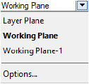
The current working plane displays in bold; if it has not yet been saved, it displays as Working Plane.
Alternatively, select Window > Palettes > Working Planes and double-click the name of the plane from the Working Planes palette.
The selected working plane displays.
To access unsaved working plane positions, select Modify > Working Plane > Next Working Plane and Modify > Working Plane > Previous Working Plane. The commands cycle through ten working plane positions.
~~~~~~~~~~~~~~~~~~~~~~~~~
The three buttons on the View bar control how the working plane is viewed and how it interacts with certain tools and commands.
Button |
Description |
|---|---|
Look At Working Plane
|
Changes the view to be perpendicular to the working plane; similar to the Top view under the View menu in that you are looking straight at the working plane |
Active Layer Plane Views
|
Sets the active layer plane as the reference for tools such as the Flyover tool, Walkthrough tool, and other viewing tools; used with the Flyover tool’s rotation center mode |
Working Plane Views
|
Sets the working plane as the reference for tools such as the Flyover tool, Walkthrough tool, and other viewing tools; used with the Flyover tool’s rotation center mode |
~~~~~~~~~~~~~~~~~~~~~~~~~
Tool |
Tool set |
|---|---|
Align Plane |
3D Modeling |
The Set Working Plane tool and Align Plane tool share the same position on the tool set. Click and hold the mouse on the visible tool to open the Ferramentas Pop-out list and select the desired tool.
When the working plane has been set to the desired location, it can be used to position 3D objects. One way to align objects precisely in 3D space is to align them to the working plane, using the Align Plane tool.
|
Clique aqui para uma dica em vídeo sobre este tópico (requer acesso à internet) |
To align an object to the working plane with three points:
1 In a 3D view, set the working plane location.
2 Select the object to align to the working plane.
3 Click the tool.
4 Click a location on the object to align with the origin of the working plane.
5 Click a second point on the object to define the X axis.
The line between the first and second points defines the X axis position.
6 Click a third point on the object to define the Y axis.
The line between the second and third points defines the Y axis position.
The object aligns itself to the working plane as defined by these points. If the surface was mistakenly aligned to the wrong side of the working plane, use the Mirror tool to flip the object to the opposite side of the working plane.

A rendered object can be aligned to the working plane.
To align a rendered object to the working plane:
1 Select a 3D view and a polygon rendering mode (Unshaded Polygon, Shaded Polygon, Shaded Polygon No Lines, or Final Shaded Polygon) for the drawing.
2 Select the 3D object to align to the working plane.
3 Click the tool.
The cursor changes to a pointing hand when over the surface of a rendered object.
4 Click the surface to align to the working plane.

The object’s selected surface is aligned to the working plane.
Setting different visibilities for individual classes and layers within a drawing can make it easier to add, select, snap to, and edit objects, and to establish the desired appearance within viewports and saved views. There is a variety of ways to control visibility, depending on your needs, including setting global visibilities for the drawing, and setting the visibilities of specific classes and layers.
Objects that are in both the active class and active layer always have normal visibility, regardless of the visibility settings. For objects that are in an inactive class and/or layer, the visibility is controlled by the lower visibility setting. For instance, if an object is in the active class, and therefore has normal visibility, but is on an inactive layer that is set to gray, the object is grayed. (See Organizando o Desenho for a discussion of classes and layers as the building blocks on which to structure a drawing.)
The level of gray for grayed layers and classes can be adjusted for Printing a File.
• Class Options and Layer Options commands allow you to establish global visibilities for the inactive classes and design layers in the drawing. As you change among classes and layers, the active class and active layer always display normally. All other classes and layers display and can be snapped or modified (or not snapped or modified) according to the class and layer options commands.
These global settings establish the maximum visibilities for the drawing. Individual inactive classes and layers cannot be set to a higher level of visibility with the Visibility columns or Visibility tool than the class/layer options setting allows, though they can be set to a lower level of visibility (such as made invisible or grayed).
• Visibility columns appear in the Organization dialog box, Navigation palette (Vectorworks Design Series required), and other places throughout Vectorworks. They provide lists of the classes and layers in the drawing, which can be individually set to fully visible, invisible, or grayed.
• The Visibility tool (Design Series required) can be used either to set the visibilities of specific classes and layers, or to make global changes to class and layer visibilities. Rather than setting visibility directly for the class or layer itself, as with the Visibility columns, the Visibility tool sets visibilities for the classes and layers of clicked objects in the drawing.
Both the Visibility columns and Visibility tool can be used to set class and layer visibilities for the drawing area and viewports; Visibility columns can be used to set visibilities for saved views, as well.
Visibility Change |
Method |
Description |
|---|---|---|
Set global visibilities for inactive classes and design layers |
Select the Class Options and Layer Options commands to set the master visibility for all inactive layers in the drawing area |
Setting Global Visibility with Class and Design Layer Options |
Quickly turn classes or layers on/off globally |
Use the Visibility tool preferences and double-click operation; use the Navigation palette (Vectorworks Design Series required) |
Global Visibility Changes with the Visibility Tool; The Navigation Palette |
Change the visibility of the individual class or layer for an object clicked in the drawing area or viewport |
Use the Visibility tool modes from the View bar |
|
Set the visibility of individual classes/layers in the drawing area |
Use the Visibility columns in the Organization dialog box Details view and elsewhere |
Layer or Class Visibility Changes in the Drawing Area Using Visibility Columns |
Set the visibility of individual classes/layers in viewports and saved views |
Use the Visibility columns in the Organization dialog box Visibilities view and elsewhere |
Layer or Class Visibility Changes for Viewports and Saved Views Using Visibility Columns |

~~~~~~~~~~~~~~~~~~~~~~~~~
Command |
Path |
|---|---|
Class Options (or Layer Options) |
• View • Document context menu |
The Class Options and Layer Options commands control how all the inactive classes or design layers in a drawing display. For example, a drawing project can be set to display only the active class, temporarily hiding all objects assigned to other classes. When you make a different class active, the objects in the new active class display, and all other objects are hidden. This makes it easier to display, snap to, and edit objects in the current class or design layer.
These commands establish the maximum allowed visibility settings for the inactive classes and layers. Individual inactive classes and layers can be set to lower visibility (made invisible or grayed) using the Visibility Columns or The Visibility Tool, but if class/layer options are set to Active Only or to one of the gray settings, inactive classes/layers cannot be displayed with normal visibility (see Concept: Visibility of Drawing Elements).
Objects that are in both the active class and the active layer always display with normal visibility.
To change the class or layer visibility options:
1 Select the command and then the option.
Command |
Description |
|---|---|
Displays only objects in the active class/layer; only the active class/layer prints |
|
Displays the active class/layer normally and all other classes/layers are grayed (except for those set to invisible); even though visible, objects in grayed classes/layers cannot be edited |
|
Displays the active class/layer normally and all other classes/layers are grayed (except for those set to invisible); objects in any normally displayed or gray class/layer can be snapped to. Only objects in the active class/layer can be edited. |
|
All classes/layers display normally, except for those set to invisible or grayed; even though visible, objects in classes/layers other than the active class/layer are not editable and cannot be snapped to |
|
All classes/layers display normally, except for those set to invisible or grayed; objects in any normally displayed or gray class/layer can be snapped to. Only objects in the active class/layer can be edited. |
|
All classes/layers display normally, except for those set to invisible or grayed. Objects in any normally displayed or gray class/layer can be snapped to; only objects in normally displayed classes/layers can be edited. (An object on another layer can only be edited if its layer scale and view are the same as those of the active layer.) Locked objects display with gray highlighting. |
2 The current class or design layer visibility changes accordingly.
|
Clique aqui para uma dica em vídeo sobre este tópico (requer acesso à internet) |
The active class and design layer are always visible. Each inactive class and layer can be set to be visible, invisible, or gray. These visibilities can be set independently for the drawing area, saved views, and viewports. For maximum usability, class and design layer visibilities can be set with the Visibility columns accessed in multiple places in the Organization dialog box, in the Navigation palette (Vectorworks Design Series required), and also in other dialog boxes. The Visibility columns work the same way wherever they are used. Visibility set with the columns is subject to the class and layer options settings.
For an alternative workflow, you can use The Visibility Tool to set visibility for the class and/or layer of a clicked object in the drawing area or in a viewport.
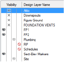
To change the setting for a single class or design layer, click on one of its visibility columns. To change the settings for multiple items, click a visibility column as follows:
• Press the Ctrl key (Windows) or Cmd key (Mac) and click selected class or layer rows.
• Press the Shift key and click the first and last rows of a group of classes or layers.
• Press the Alt key (Windows) or Option key (Mac) and click any row to change all classes or layers.
When Exibindo Classes em Ordem Hierárquica, change the visibility setting of a group header to change the visibility of all of its subclasses.
Column |
Description |
|---|---|
Visible
|
Class/design layer is visible; objects in this class/layer display when another class/layer is active |
Invisible
|
Class/design layer is invisible; objects in this class/layer display only when the class/layer is active |
Gray
|
Class/design layer is gray; objects in this class/layer are grayed when another class/layer is active |
Don’t Save
|
For saved views, a fourth column displays to the right of the other columns. When selected, class/design layer visibility is not saved for the saved view; the current class/layer visibility is used when the view is displayed. |
Use A Janela de Diálogo Organização or The Navigation Palette (Design Series required) to set the visibilities of classes and design layers in the drawing area.
To set the class and design layer visibilities for the drawing area:
1 From the Organization dialog box, select the Classes or Design Layers tab in Details view.
2 Click in the Visibility column for each class or design layer to set its visibility.
3 To see the changes before saving them, click Preview.
Class and design layer visibility in the drawing area are also affected by the Class Options and Layer Options settings. See Setting Global Visibility with Class and Design Layer Options for details.
Use A Janela de Diálogo Organização to set the visibilities of classes and design layers in existing viewports and saved views. You can also set these visibilities while creating and editing classes, design layers, viewports, and saved views, as described in the following topics:
• Creating Classes and Setting Class Properties
• Criando Camdas and Definindo Propriedades da Camada de Projeto
To set the class and design layer visibilities for viewports and saved views:
1 From the Organization dialog box, select a tab in Visibilities view.
Organization Dialog Box Tab |
Sets Visibility of |
|---|---|
Classes |
Classes in viewports and saved views; if classes are displayed in hierarchical order and a class group header is selected, the viewport and saved view lists are disabled |
Design Layer |
Design layers in viewports and saved views |
Viewports |
Classes and design layers in a viewport |
Saved Views |
Classes and design layers in a saved view |
2 Select one or more class, design layer, viewport, or saved view names and set the Visibility settings for classes and design layers.
3 On the Saved Views tab, change the active design layer and class, and the design layer and class options.
4 To see the changes before saving them, click Preview (not available on the Saved Views tab).
|
Clique aqui para uma dica em vídeo sobre este tópico (requer acesso à internet) |
~~~~~~~~~~~~~~~~~~~~~~~~~
 The
Visibility Tool
The
Visibility Tool
The Visibility tool is on the Basic palette.
The Visibility tool changes the visibility of either the layer or class associated with a clicked object. If you click an object in a sheet layer or design layer viewport, only the visibility in that viewport changes (with some exceptions). You can also make rapid changes to the visibilities of multiple layers or classes in the drawing at one time by double-clicking the tool itself.
Several modes are available to specify whether to change class or layer visibility, and to set the type of visibility change to make.

Mode |
Description |
|---|---|
Classes |
Affects the visibility of the clicked object’s class |
Layers |
Affects the visibility of the clicked object’s layer |
Visible |
Sets the clicked object’s class or layer to visible |
Invisible |
Hides the clicked object’s class or layer |
Greyed |
Sets the clicked object’s class or layer to gray |
Preferences |
Specifies the global visibility behavior when the Visibility tool is double-clicked |
Class and design layer visibility in the drawing area are also affected by the Class Options and Layer Options settings. See Setting Global Visibility with Class and Design Layer Options for details.
|
Clique aqui para uma dica em vídeo sobre este tópico (requer acesso à internet) |
~~~~~~~~~~~~~~~~~~~~~~~~~
 Layer or Class Visibility Changes
Using the Visibility Tool
Layer or Class Visibility Changes
Using the Visibility ToolTool |
Tool set |
|---|---|
Visibility
|
Basic |
Use the Visibility tool to change the visibility of the class or layer of a clicked object in the drawing area or viewports.
Alternatively, to change the visibility of one or more classes or layers selected from a list of all classes/layers in a drawing, use the Visibility Columns.
To change class or layer visibilities based on a clicked object:
1 Click the tool.
2 Click Classes or Layers mode, and then select whether to make the object’s class or layer Visible, Invisible, or Greyed.
3 If the class or layer to be changed is currently invisible, ensure that the class or layer options are not set to Active Only. Press and hold the shortcut key (V by default) for the Visibility tool to temporarily make all classes (in Classes mode) or layers (in Layers mode) visible. If the cursor is over a viewport, all classes or layers in the viewport become visible.
In Classes mode, if the cursor is over a design layer viewport that is set to use the class visibilities of the document, all document classes become visible (which includes the classes in the viewport).
4 Move the cursor over a drawing object that is in the class or layer to be changed. All objects that will be affected by the visibility change are highlighted. In addition, a screen tip indicates the name of the class or layer that will be changed, as well as its current visibility setting. If the object is in a viewport, the screen tip also indicates the name of the viewport in which the change will be made.
In Classes mode, if the object is in a design layer viewport that is set to use the class visibilities of the document, the screen tip does not show the viewport name. This indicates that a click on the object will change the class visibility for the document (not the viewport)—including objects of that class that are not in the viewport.
5 Click the object to change the visibility setting for its class or layer.
The object’s class or layer is set to visible, invisible, or gray, and the Message bar shows the change that occurred. The Navigation palette (Vectorworks Design Series required) updates to display the new visibility status. On a design layer, changes to class visibility redraw the entire drawing; changes to layer visibility redraw the layer.

When you use the Visibility tool to make class or layer changes, several factors may prevent the visibility from changing as expected.
• The layer and class options control the visibility of objects in the inactive layers and classes. For example, if the layer options are set to gray objects in inactive layers, grayed objects do not become fully visible when clicked with the Visibility tool. (See Setting Global Visibility with Class and Design Layer Options.) An alert displays in this situation.
• The Visibility tool cannot hide or gray the active class or layer immediately, since the active class or layer is always set to visible. An alert displays in this situation.
• A container object (such as a symbol or a group) and its component parts can belong to different classes, and their visibilities can be set differently. For example, if the classes of the individual objects that make up a symbol are set to invisible or gray, they do not become visible when the symbol’s class is made visible.
• In a viewport, changes to class or layer visibility display immediately if the viewport has a background render mode of Wireframe, Sketch, or OpenGL. For other render modes, you must update the viewport to see the visibility change. An alert displays in this situation.
• If a design layer viewport (Vectorworks Design Series required) is embedded in another viewport, several factors affect the behavior of the Visibility tool. See Visibility Tool Behavior in Embedded Viewports for more information.
~~~~~~~~~~~~~~~~~~~~~~~~~
 Global Visibility Changes
with the Visibility Tool
Global Visibility Changes
with the Visibility ToolTool |
Tool set |
|---|---|
Visibility
|
Basic |
The Visibility tool can make global changes to the class or layer visibilities of a drawing. In a complex drawing, for example, this can be an easy way to quickly show the classes or layers only of selected objects. All classes or layers can easily be set to show again. This feature does not affect visibilities in viewports.
To make global changes to the visibility of classes or layers:
1 To make changes to the class or layer visibility of selected objects, select the objects first.
The objects do not need to be in the same class or layer.
2 Click the tool, and then click Preferences.
The Visibility Tool Preferences dialog box opens. Specify the effect to occur when the Visibility tool is double-clicked.
► Clique para exibir/ocultar os parâmetros.
3 Double-click the Visibility tool to execute the selected action.
The classes or layers in the drawing area are set to visible or invisible as specified, and the Message bar shows the change that occurred. The Navigation palette (Vectorworks Design Series required) updates to display the new visibility status.
When you use the Visibility tool to make global changes, several factors may prevent the visibility from changing as expected.
• The layer and class options control the visibility of objects in the inactive layers and classes. For example, if the layer options are set to gray objects in inactive layers, grayed objects do not become fully visible when the Visibility tool is double-clicked. (See Setting Global Visibility with Class and Design Layer Options.) An alert displays in this situation.
• The Visibility tool cannot hide the active class or layer immediately, since the active class or layer is always set to visible. An alert displays in this situation.
• A container object (such as a symbol or a group) and its component parts can belong to different classes, and their visibilities can be set differently. For example, if the classes of the individual objects that make up a symbol are set to invisible or gray, they become visible only when the first double-click option (Makes all classes visible) is used.
~~~~~~~~~~~~~~~~~~~~~~~~~
 Visibility
Tool Behavior in Embedded Viewports
Visibility
Tool Behavior in Embedded ViewportsDesign layer viewports (Vectorworks Design Series required) can be embedded in both sheet layer and design layer viewports, and they can be referenced or not. There are settings in the viewport properties of all of these viewports to control the way classes and layers display, which affect the behavior of the Visibility tool.
The following cases describe the conditions under which the Visibility tool cannot change the visibilities of the class or layer of a clicked object, when the object is in a design layer viewport that is embedded in another viewport.
• The top-level viewport is a sheet layer viewport, and it is set to use the class or layer visibilities of the embedded viewport. The tool can only change the top-level viewport’s visibility setting for the class or layer of the embedded viewport itself. The tool cannot change the visibility for the class or layer of an object inside the embedded viewport.
• The top-level viewport is a sheet layer viewport, and it is not set to use the class or layer visibilities of the embedded viewport. However, the embedded viewport is referenced. In a referenced viewport, each class can either keep its own settings, or take on the settings of the document in which it is embedded. In Classes mode, if you click an object whose class is set to keep its own settings, the tool changes the top-level viewport’s visibility setting for the class of the embedded viewport itself. In Layers mode, the tool can only change the top-level viewport’s visibility setting for the layer of the embedded viewport itself.
• The top-level viewport is a design layer viewport, and the embedded viewport is referenced. In Classes mode, if you click an object whose class is set to keep its own settings, the tool changes the top-level viewport’s visibility setting for the class of the embedded viewport itself.
• The top-level viewport is a design layer viewport. In Layers mode, the tool can only change the top-level viewport’s visibility setting for the layer of the embedded viewport itself. The tool cannot change the visibility for the layer of an object inside the embedded viewport.
The following cases describe the conditions under which the Visibility tool changes the class visibilities for the entire document, when you click an object in a design layer viewport that is embedded in another viewport.
• The top-level viewport is a design layer viewport, and it is set to use the class visibilities of the document. The embedded viewport is not referenced. The tool changes the visibility of the class of the clicked object, not only in the viewport, but in the entire document.
• The top-level viewport is a design layer viewport, and it is set to use the class visibilities of the document. The embedded viewport is referenced. If the clicked object belongs to a class that is set to take on the settings of the document, the tool changes the class visibility for the entire document.
~~~~~~~~~~~~~~~~~~~~~~~~~