
Os itens do submenu Visualizar> Vistas permitem a você mudar a orientação da imagem do seu projeto na Área de Desenho. O Vectorworks oferece 15 opções de Vistas, que podem ser divididas em 4 categorias básicas:
Para mudar entre as diferentes vistas:
No menu Visualizar, selecione no submenu Vistas a opção desejada.
A vista muda e uma marca de checagem é exibida na frente da vista ativa das vistas listadas na Janela Atual/Vistas.
A referência para a vista, o plano de trabalho ou plano de chão, pode depender da seleção na paleta de Planos de Trabalho (veja Working Plane View and Modes).
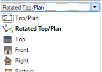
Quando uma vista Topo/Planta Rotacionada existir (Vectorworks Design Series apenas), a tecla 0 do teclado numérico irá mostrar a Vista Topo/Planta Rotacionada ao invés da vista Topo/Planta padrão (sem rotação). Pressione a tecla 0 uma segunda vez para mudar para a vista Topo/Planta padrão sem rotação.
A Barra de Visualização também oferece rápido acesso às vistas padrões. Clique no menu da vista atual e selecione uma vista standard na lista que é mostrada. Se a vista é diferente de uma vista padrão a mensagem Vista Personalizada é mostrada como a vista atual.

O comando Projeção altera a maneira que o Vectorworks exibe a geometria 3D do desenho na tela 2D de seu monitor ou no papel impresso.
Os comandos de projeção relacionados a perspectiva adicionam uma distorção ao desenho de modo que os objetos mais distantes pareçam menores que os objetos que estão mais próximos. Estas vistas se aproximam mais de como um modelo em 3D seria visto no mundo real. A vista de perspectiva pode ser recortada ou não recortada (veja Perspectiva).
Além da projeção 2D Topo/Planta padrão, o Vectorworks tem nove outros modos de projeção 3D.
Para mudar os modos de projeção:
A partir do menu Visualizar > Projeção, selecione a projeção específica.
A barra de visualização também oferece acesso rápido aos comandos de projeção. Clique na projeção atual e escolha uma projeção a partir da lista que é exibida.

Modo de Projeção |
Descrição |
|---|---|
Este modo é equivalente ao usado para desenhos normais em 2D. Use esta vista quando você está desenhando objetos 2D para melhor precisão. |
|
Esta projeção exibe o desenho em uma projeção 3D sem distorção - onde os objetos aparecem com seu tamanho exato independente de sua distância ao plano do observador. |
|
Exibe uma projeção do desenho similar ao obtido com uma lente telefoto |
|
Exibe uma projeção do desenho similar ao obtido com uma lente retrato |
|
Exibe uma projeção do desenho similar ao obtido com uma lente objetiva grande angular ou olho de peixe |
|
Selecione para definir uma perspectiva personalizada numericamente. A janela Definir Distância de Perspectiva é exibida. Digite o valor de perspectiva personalizada no campo Distância e então clique em OK. Quanto menor for o valor, maior será o ângulo da perspectiva. |
|
Usada raramente, é concebida para mostrar uma vista frontal (ou outra vista ortogonal não distorcida) junto com sua profundidade. O comprimento das linhas ao longo do eixo Z, mostrando a espessura de um objeto, é representado em seu comprimento verdadeiro. Este comprimento verdadeiro distorce a imagem do objeto, fazendo ele parecer mais espesso do que ele realmente é. No entanto, neste modo de projeção você pode gerar perspectivas nas quais você pode medir diretamente. |
|
Similar à Cavaleira Oblíqua. No entanto, neste modo, as linhas para a profundidade são reduzidas em 50 %. Esta redução distorce o comprimento real destas linhas, mas representa uma vista mais "natural" do objeto. Você pode ainda usar este modo para tirar medidas de vetores perpendiculares ao plano de projeção (ao longo do eixo Z) de um desenho impresso, mas você precisa multiplicá-lo por dois para obter a dimensão real. |
Os modos de apresentação OpenGL e Renderworks não suportam projeções oblíquas; arquivos renderizados no modo OpenGL ou Renderworks são convertidos de Projeção oblíqua para Projeção ortogonal após salvo. Para apresentar nestas projeções utilize a opção Polígono ou Linhas Escondidas.
Uma preferência do Vectorworks define a projeção preferida, aplicada sempre que a vista de um desenho é alterada da vista Topo/Planta em uma vista 3D; veja Aba 3D.
Em uma vista de perspectiva sem recorte, a rolagem dentro do desenho e a utilização das ferramentas Deslocamento e Zoom causarão o movimento da câmera de perspectiva enquanto a vista permanece centralizada na janela. Como não há objetos na vista para serem usados como referência, um indicador especial o ajudará a se orientar durante o movimento.

A ferramenta Translação de Vista também pode ser usada para se movimentar por um modelo e ajustar a distorção de perspectiva enquanto se está na projeção de perspectiva. Veja Translação de Vista.
~~~~~~~~~~~~~~~~~~~~~~~~~

A projeção de perspectiva pode ser exibida na vista de modelagem sem recorte ou na vista de apresentação com recorte. A projeção em perspectiva com recorte pode ser definida para todo o documento na aba Display na janela de diálogo Preferências do documento. A projeção Perspectiva Recortada é definida para todo o documento na tab Display na janela de Preferências do Documento; Veja Aba Visualização.
Na vista com recorte um quadro de corte será exibido na janela de vista de perspectiva, o que é útil para apresentar, por exemplo, a elevação do modelo na vista de perspectiva. Você pode ajustar o recorte arrastando os cantos para aumentar ou diminuir o tamanho da janela.
Na vista sem recorte uma representação de horizonte sombreado é mostrado no fundo. O horizonte oferece uma indicação visual da posição vertical do observador em relação aos objetos na cena. O horizonte não será impresso ou exportado. A cor verde representa o chão abaixo do horizonte, e a cor azul representa o céu acima do horizonte, o que ajuda na orientação. As cores do chão e do céu podem ser alteradas usando a janela Aparências das Dicas Interativas. Veja Configurando as Dicas Interativas de Tela.
In Vectorworks, it is possible to divide the drawing area to display multiple drawing views at the same time, and move efficiently among them to draw and edit in any of the view panes. You can also open floating view panes outside the application window, and size and place them as desired. Working in a multiple view panes layout not only allows you to see the drawing from different view points at once, but it even makes it possible to begin drawing in one view pane and complete the action in another.
Multiple view panes are not viewports (though a viewport can be shown in a view pane), but are different “live” and fully interactive working views of the same drawing. Just as changes made in a single view are reflected when you change the drawing view, changes made in one view pane are reflected in real time in the other view panes.
Multiple simultaneous view panes can include different standard views, projections, and rendering styles, display a combination of design and sheet layer views, and show different parts of the drawing. The views can have the same layer and class visibility settings for all panes, or different settings for each.
|
Clique aqui uma uma díca em vídeo sobre este tópico (requer acesso à internet) |

There are several general operating behaviors and principles that guide working with multiple view panes:
• Only one pane is active at a time. To switch among the view panes, click a different pane label to make it active; the blue title flag and border change to indicate the new active pane. When a new pane is activated, the displays for class and layer options, standard views, rendering style, and so on change to reflect the settings for the new active pane.
You can simply click in a pane to make it active, but that could result in accidental selection of an object in the pane.
• Any time you enable multiple views, the current view in the application window becomes the active view in the multiple pane layout.
• Although the editing actions that are completed inside a view pane can be undone, view pane actions themselves, such as splitting and closing panes, cannot be undone. Once a view pane is closed, that view cannot be recovered; unless it was previously saved as a saved view, it must be set up again.
• Because multiple pane viewing is a working layout, not meant for presentation, the entire view panes layout cannot be printed. Only the active view pane prints.
• Multiple view pane operations may not be fully supported when the Vista Unificada de Camadas feature is disabled.
• Moving the drawing area’s scroll bars affects only the active pane.
• It is possible to begin drawing in the active pane and complete the step in a different pane. Without changing tools, simply move the cursor to the other pane and complete the operation there. For example, a shape can be selected and the Push/Pull tool clicked in Top/Plan view in one view pane, and then the cursor moved into a second view pane set to an isometric view to complete the extrude. As the cursor moves over the selected object in the second view pane, the extrude previews, allowing you to complete the push-pull operation accurately.
If a particular operation cannot be completed in a different pane, the action stops when the cursor moves over the other pane.
• Object Editing Mode works while in multiple drawing view, and can be used with different objects in different view panes simultaneously.
• The default initial multiple pane view, including the number of panes and the views in each pane, can be changed by Criando Gabaritos with the desired default multiple view pane layout.
• The multiple view pane layout can be customized to include as many panes as needed for an efficient workflow, including floating panes that can be moved and placed as wanted. Panes can be resized for the most appropriate layout. (See Changing the Multiple View Pane Layout.)
• When multiple view panes are disabled, the active view becomes the single view. When multiple view panes are re-enabled, they reopen in the same positions and with the same settings they had before, with the exception that the current single view becomes the new active view.
• Floating view panes are created using a command; they cannot be created by dragging a view pane out of the application window.
• Floating view panes can be resized and moved independently of the application window, and are minimized, maximized, and closed like a palette.
• Unlike view panes in the application window, floating view panes do not toggle on and off with the Enable Multiple View Panes command. Floating view panes remain visible as long as the Vectorworks file they are in remains the active document.
• Design layer view panes can be set to use the same class and layer visibilities and clip cube for each view pane with the Use Same Visibilities in All Panes command. All design layers in the drawing adopt the same visibility settings as the pane that is active when the command is enabled. The command can be disabled to set different visibilities for some view panes, or to use a different clip cube in some panes.
• When they are set to the same visibilities, every change made to visibilities and the clip cube in any view pane automatically makes the same change in all design layer panes.
~~~~~~~~~~~~~~~~~~~~~~~~~
Command |
Path |
View bar |
|---|---|---|
Enable Multiple View Panes |
View > Multiple View Panes |
|
To use multiple drawing views:
1 In any drawing view, select the command or click the View bar button.
Alternatively, press the shortcut key for the command (m by default).
The drawing area is divided into multiple view panes; the single view when the command is selected becomes the active view.
2 To set all panes to the same class visibilities, layer visibilities, and clip cube, select View > Multiple View Panes > Use Same Visibilities in All Panes. Deselect the command to set visibilities independently in each view pane.
3 Edit the drawing in the active view pane; to configure and draw in a different pane, click in the pane or on the pane title flag to make it active.
You can begin a drawing operation in the active pane and conclude it in another pane.
4 To return to a single view pane, select the command again.
~~~~~~~~~~~~~~~~~~~~~~~~~
When multiple view panes are enabled, the pane layout can be altered by resizing, adding, and deleting view panes that are contained within the application window and by adding one or more floating view panes.
To resize view panes, hold the cursor over the pane splitter until the resize cursor appears, and then drag the cursor to the desired location. Both adjacent view panes resize.

Command |
Path |
|---|---|
Split Vertically/Horizontally |
• View > Multiple View Panes • Context menu |
Split an existing view pane horizontally or vertically to create a second pane within the same space.
To split a view pane:
1 Click in the pane to be split, to make it the active pane.
2 Select the command, or right-click on the pane’s title flag and select the context menu command.
The pane is split into two equally sized panes with the same view; a panel splitter allows them to be resized as needed. The views and configurations can be changed independently.

Command |
Path |
|---|---|
Close Active View Pane |
• View > Multiple View Panes • Context menu |
To close a view pane within the application window:
1 Click in the pane to be closed, to make it the active pane.
2 Select the command, or right-click on the pane’s title flag and select the context menu command.
The active pane is closed and an adjacent pane is resized to fill the space. This action cannot be undone; to redisplay the view in the closed pane, a new pane must be added and the view set up as desired.
If multiple panes adjacent to the active pane are aligned evenly with the active pane, there is no way to control which adjacent pane will be resized to fit the space vacated by the closed pane. To ensure the desired pane layout, resize the active pane before closing it.


Command |
Path |
|---|---|
Create Floating View Pane |
• View > Multiple View Panes • Context menu |
Create a floating view pane from any of the following:
• Single pane view (multiple view panes are disabled)
• Any view pane, when multiple view panes are enabled
• Another floating view pane
• An existing saved view (Vectorworks Design Series required)
The floating view pane can be configured and edited independently of other view panes. It can be resized, moved (including to another screen on a multiple-monitor setup), and closed like a palette. A floating pane remains visible, regardless of whether multiple view panes are enabled.

To add a floating view pane:
1 If multiple view panes are enabled, click in the pane to be duplicated as a floating pane, to make it the active pane.
2 Select the command, or right-click on the pane’s title flag and select the context menu command.
You can also create a floating view pane from a saved view in the Navigation palette (Design Series required). On the Saved Views tab, right-click the saved view name, and select Activate in new pane from the context menu.
~~~~~~~~~~~~~~~~~~~~~~~~~
Várias ferramentas simulam movimento sobre e através do desenho.
Ao usar estas ferramentas o modelo apresentado pode ser exibido temporariamente com a apresentação OpenGL, mesmo quando o modo de apresentação for diferente. Quando o movimento parar o programa fará a apresentação da nova vista do modelo. Além disso, em um desenho altamente complexo, o programa irá remover temporariamente alguns dos detalhes afim de aumentar a velocidade do movimento. Quando o movimento parar os detalhes serão recolocados.
Estas ferramentas apresentam certos botões na barra Ferramentas que representam modos verdadeiros, e outros que operam como botões de comandos. Quando essas ferramentas são utilizadas, a barra Dados exibe informações que ajudam a orientar a vista.
A referência para a vista (seja plano de camada ou plano de trabalho) depende dos botões do plano de trabalho na barra Exibir; veja Working Plane View and Modes.
~~~~~~~~~~~~~~~~~~~~~~~~~
Tool sets |
|
|---|---|
Sobrevôo
|
• Basic • 3D Modeling • Visualization |
A ferramenta Sobrevôo irá simular a navegação de um observador sobrevoando o modelo.
Os diferentes movimentos direcionais da ferramenta Sobrevôo são controlados arrastando o mouse sobre um centro de rotação selecionado. Os botões na Barra de Ferramentas selecionam o centro de rotação.

Modo |
Descrição |
|---|---|
Centro da Vista |
Define automaticamente o centro de rotação com base na vista atual |
Origem Interativa |
Define o centro de rotação para o movimento de sobrevôo com um clique do mouse |
Centro de objeto |
Define o centro de rotação para o centro dos objectos selecionados; se não há objetos selecionados, define o centro de rotação para o centro dos objetos visíveis |
Origem do Plano de Trabalho Atual |
Utilizará o ponto de origem do Plano de Trabalho atual como centro de rotação para o movimento de sobrevôo |
Centro do Plano de Chão |
Utilizará o centro do Plano de Chão como centro de rotação para o movimento de sobrevôo |
Preferência |
Define a velocidade do sobrevôo em resposta aos movimentos do mouse |
Para sobrevoar um desenho:
1.No conjunto de ferramentas Modelagem 3D, selecione a ferramenta Sobrevôo.
2 Clique o botão de modo desejado na Barra de Ferramentas.
3 Para sobrevoar o desenho, clique no desenho e arraste na direção desejada, enquanto mantém o botão do mouse pressionado. Pare o movimento soltando o mouse. Alternativamente, sobrevoe o desenho usando um atalho equivalente no teclado/mouse.
Para alterar a velocidade do sobrevôo, clique em Preferências. A caixa de diálogo Preferências Sobrevôo é aberta. defina a sensibilidade de rotação.
Movimento do Mouse |
Tecla de Atalho |
Descrição |
|---|---|---|
Arrastar para Esquerda-Direita |
|
Vira para Esquerda-Direita ao redor do centro de rotação selecionado |
Arrastar para Cima-Baixo |
|
Vira para Cima-Baixo ao redor do centro de rotação selecionado |
Movimento na Direção do Centro da Janela |
Alt + Arrastar para Direita (Win) ou Option + Arrastar para Direita |
Move o observador na direção do centro de rotação (somente em Projeção Perspectiva) |
Movimento Afastando do Centro da Janela |
Alt + Arrastar para Esquerda (Win) ou Option + Arrastar para Esquerda |
Afasta o observador do centro de rotação (somente em Projeção Perspectiva) |
Movimento para Baixo na Direção do Plano de Chão |
Alt + Arrastar para Cima (Win) ou Option + Arrastar para Cima (Mac) |
Move o observador para baixo na direção do plano de chão (projeção perspectiva e/ou ortogonal) |
Movimento para Cima a partir do Plano de Chão |
Alt + Arrastar para Baixo (Win) ou Option + Arrastar para Baixo (Mac) |
Move o observador para cima a partir do plano de chão (projeção perspectiva e ou ortogonal) |
|
Tecla Shift |
Restringe a rotação ao eixo K do plano de trabalho ativo ou ao eixo Z global. |
Enquanto outra ferramenta estiver ativa, pressione e mantenha pressionado a roda do mouse e a tecla Ctrl (Windows) ou Control (Mac) simultaneamente para ativar a ferramenta Sobrevôo. Oriente a vista conforme desejado, e solte o botão do mouse. A ferramenta anterior se tornará ativa novamente automaticamente.
Este recurso não irá funcionar propriamente se a roda do mouse estiver associada a uma função personalizada nas configurações do mouse. Por exemplo, se a roda do mouse está definida para realizar uma função de apagar quando pressionada, um clique com a roda do mouse no Vectorworks apagará ao invés de ativar a ferramenta Sobrevôo (a configuração específica requerida para este recurso depende do tipo de mouse sendo usado).
~~~~~~~~~~~~~~~~~~~~~~~~~

A ferramenta Caminhar Através está na barra de Visualização.
A ferramenta Caminhar Através permite a você "passear" através de seu modelo 3D.
Esta ferramenta opera na projeção de perspectiva. Quatro modos, o parâmetro Altura do Observador e diversas chaves modificadoras oferecem flexibilidade ao manipular a posição do observador e o ângulo de visão antes e durante a navegação.

Modo |
Descrição |
|---|---|
Caminhar |
Move o observador pelo desenho |
Olhar em Volta |
Muda o ângulo de visão para cima, para baixo, para a esquerda ou para a direita enquanto o observador permanece parado |
Elevador |
Sobe ou desce o observador |
Gamer |
Semelhante a muitos jogos de vídeo, usa o teclado (para mover) e o mouse (para direcionar para a esquerda e para a direita e para cima e para baixo) para mover o visualizador pelo desenho. |
Preferência |
Especifica opções para o modo Gamer; vejaVisualizar um Modelo no Modo Gamer |
Altura do Observador |
Permite especificar a altura do observador acima do plano de chão. Este valor é atualizado automaticamente se o modo Elevador for utilizado. Ele também reflete a altura do observador conforme definido por qualquer outra ferramenta de visualização. |
Se a ferramenta Caminhar Através estiver sendo usada, a barra Dados exibe as seguintes informações para ajudar a orientar a visualização.
Barra de Dados |
Descrição |
|---|---|
Guinada |
Exibe o ângulo (de 0 a 360 graus) entre a direção da caminhada e o eixo Y positivo, para descrever a direção do movimento no plano de camada ativo. Uma guinada de 90 graus indica um movimento na direção do eixo X positivo. Uma guinada de 180 graus indica um movimento na direção do eixo Y negativo. |
Inclinação |
Exibe o ângulo de visualização. Um valor de zero graus indica que o observador está olhando diretamente em frente. Um valor de 45 graus indica que o observador está olhando para cima num ângulo de 45 graus a partir da horizontal. |
Observador X/Y/Z |
Exibe a posição do observador em relação ao plano de camada ativo |
Se a barra de dados flutuante estiver ativada, você pode ocultar a barra de dados durante a explicação passo a passo. Selecione Preferências e, em seguida, selecione Ocultar barra de dados flutuante.
~~~~~~~~~~~~~~~~~~~~~~~~~
Modo |
Ferramenta |
Conjunto de Ferramentas |
|---|---|---|
Caminhada |
Caminhar Através
|
Visualização |
Para realizar uma caminhada por um modelo:
1. Clique na ferramenta Caminhada no conjunto de ferramentas Visualização e clique em Caminhar na barra de Ferramentas.
A projeção é alterada automaticamente para perspectiva.
2. Clique no desenho e segure o botão do mouse para realizar a caminhada.
O primeiro clique dentro do desenho, indicado por uma pequena cruz, define o ponto de controle da caminhada. O ponto de controle permite controlar o andamento da caminhada. Quanto mais você se afasta do ponto de controle, mais rápida será a caminhada. Volte ao ponto de controle para reduzir ou parar a caminhada. Para interromper a caminhada solte o botão do mouse.
3. Mova o mouse para cima (frente), para baixo (trás), para a esquerda ou para a direita para andar pelo desenho.
A barra Dados traz informações em tempo real sobre a caminhada.
Para alterar o ângulo de visão ou a altura do observador durante a caminhada, realize o movimento usando uma tecla modificadora.
Tecla modificadora |
Descrição |
|---|---|
Tecla Alt (Win) ou Option (Mac) |
Mova o mouse para alterar o ângulo de visão para cima ou para baixo (inclinação) ou para a esquerda ou para a direita (guinada) acompanhando o movimento do cursor. A posição e a altura do observador permanecerão inalteradas. Mova o mouse para um ângulo que altere a inclinação e a guinada simultaneamente para criar uma vista deslumbrante. |
Tecla Shift |
Mova o mouse para mudar a altura do observador. As posições X e Y e o ângulo de visão do observador permanecerão inalterados |
~~~~~~~~~~~~~~~~~~~~~~~~~
Modo |
Ferramenta |
Conjunto de Ferramentas |
|---|---|---|
Caminhada |
Caminhar Através
|
Visualização |
Para olhar em um modelo a partir de um ponto de observação fixo:
1. Clique na ferramenta Caminhada no conjunto de ferramentas Visualização e clique em Olhar em Volta na barra de Ferramentas.
A projeção é alterada automaticamente para perspectiva.
2. Clique no desenho e segure o botão do mouse para olhar em volta.
O primeiro clique dentro do desenho, indicado por uma pequena cruz, define o ponto de controle da observação. O ponto de controle permite controlar o andamento da observação. Quanto mais você se afasta do ponto de controle, mais rápido será o movimento. Volte ao ponto de controle para reduzir ou parar o movimento. Para interromper o movimento solte o botão do mouse.
3. Mova o mouse na direção que você deseja olhar.
A barra Dados traz informações em tempo real sobre o movimento. Para alterar o ângulo de visão ou a altura do observador durante o movimento, pressione a tecla Shift e mova o mouse para cima ou para baixo.
~~~~~~~~~~~~~~~~~~~~~~~~~
Modo |
Ferramenta |
Conjunto de Ferramentas |
|---|---|---|
Elevator |
Caminhar Através
|
Visualização |
Para alterar a altura do observador:
1. Clique na ferramenta Caminhada no conjunto de ferramentas Visualização e clique em Elevador na barra de Ferramentas.
A projeção é alterada automaticamente para perspectiva.
2. Clique no desenho, segure o botão do mouse e mova o mouse para cima ou para baixo. A barra Dados traz informações em tempo real sobre o movimento.
O primeiro clique dentro do desenho, indicado por uma pequena cruz, define o ponto de controle do movimento. O ponto de controle permite controlar o andamento do movimento. Quanto mais você se afasta do ponto de controle, mais rápido será o movimento. Volte ao ponto de controle para reduzir ou parar o movimento. Para interromper o movimento solte o botão do mouse.
Se preferir, caso você já tenha a altura do observador desejada, digite o valor no campo Altura do Observador da barra de Ferramentas. Este campo pode ser editado em qualquer modo.
~~~~~~~~~~~~~~~~~~~~~~~~~
Modo |
Ferramenta |
Conjunto de Ferramentas |
|---|---|---|
Gamer |
Caminhar Através
|
Visualização |
Para visualizar o modelo no modo Gamer:
1 Clique na ferramenta e modo
2 Clique em Preferências.
The Walkthrough Tool Preferences dialog box opens.
► Clique para exibir/ocultar parâmetros.
3 Configure os Parâmetros.
4 Click the drawing, and then use the keyboard keys to move the viewer. While moving the viewer, move the mouse to change direction.
If the Click drag drawing option is selected in the Vectorworks Preferences, hold the mouse button down while moving the mouse.
The Data bar provides real-time information about the walkthrough.
To return the mouse to its regular functions, click again to display the cursor. While the cursor displays, the mouse movements do not affect the drawing view.
~~~~~~~~~~~~~~~~~~~~~~~~~
Ferramenta |
Conjunto de Ferramentas |
|---|---|
Translação de vista
|
Visulização |
A ferramenta Translação de Vista muda a vista de um modelo 3D, especialmente quando em uma projeção em perspectiva.

Modo |
Descrição |
|---|---|
Translação de Vista |
Move o desenho ao longo do eixo X da tela quando o cursor se move para a esquerda ou direita, e ao longo do eixo Y da tela quando o cursor se move para cima ou para baixo |
Perspectiva Mover Para Dentro-Fora |
Na projeção perspectiva, arraste o mouse para cima e para baixo para mover a vista para a frente (mais perto) ou para trás (mais distante) ao longo da linha de visão atual |
Ajuste de Perspectiva |
Na projeção perspectiva, ajusta a distorção ao mover o mouse para cima (mais distorcida) ou para baixo (menos distorcida); semelhante à criação de uma perspectiva personalizado selecionando Exibir> Perspectiva> Definir Distância |
Clique duas vezes na ferramenta Translação de Vista para atualizar a vista de desenho.
Para transladar uma vista:
1.Clique a ferramenta Translação de Vista no conjunto de ferramenta Visualização.
2 Clique na janela de desenho e arraste o mouse (mantendo o botão pressionado) para realizar a translação do desenho na horizontal ou vertical. Solte o botão do mouse para parar o movimento. Alternativamente, realize a translação do desenho utilizando os botões da Barra de Ferramentas ou em suas teclas de atalhos.
Quando a ferramenta Translação de Vistas está em uso, uma Barra de Dados especial irá mostrar a seguinte informação para ajudar na orientação do observador.
Campo na Barra de Ferramentas |
Descrição |
|---|---|
Observ X/Y/Z |
Mostra a posição do observador relativa ao plano de chão. |
L/R |
Mostra o movimento para esquerda ou para a direita com relação a um eixo imaginário perpendicular a tela. |
U/D |
Mostra o movimento para cima ou para baixo com relação a um eixo imaginário perpendicular a tela. |
I/O |
Mostra o movimento para dentro e para fora com relação a um eixo imaginário perpendicular a tela. |
Distância da Perspectiva |
No modo de Ajuste de Perspectiva, mostra a distância da perspectiva |
~~~~~~~~~~~~~~~~~~~~~~~~~
Para rotacionar a vista 3D, use a ferramenta Rotação de Vista, ou especifique os valores de rotação com o comando Rotação de Vista 3D.
Ferramenta |
Conjunto de Ferramentas |
|---|---|
Rotação de Vista
|
Visualização |
A ferramenta Rotação de Vista irá rotacionar a vista atual na direção horária ou anti-horária em 3D.
As diferentes direções de deslocamento da ferramenta podem ser controladas interativamente pelo mouse ou pelos botões na Barra de Ferramentas. Os primeiros três botões da Barra de Ferramentas permitem definir o centro de rotação de uso da ferramenta. Os últimos dois botões da Barra de Ferramentas permitem realizar a rotação incremental (precisa) na direção especificada.

Modo |
Descrição |
|---|---|
Rotaciona em Torno do Centro do Objeto |
Utiliza o centro do(s) objeto(s) selecionado(s) como centro de rotação. |
Rotaciona em Torno do Centro do Plano de Chão |
Utiliza o centro do plano de chão como centro de rotação. |
Rotaciona em Torno do Centro do Plano de Trabalho |
Utiliza o centro do plano de trabalho como centro de rotação. |
Para rotacionar uma vista 3D:
1 Clique na ferramenta Rotacionar Vista no conjunto de ferramentas Visualização.
2 Para rotacionar a vista, clique na janela de desenho e arraste o mouse mantendo o botão pressionado. Mova o cursor para rotacionar a vista na direção do movimento do mouse. Solte o botão para parar o movimento de rotação. Alternativamente, use os dois botões na Barra de Ferramentas para realizar a rotação.
Modo |
Movimento do Mouse/Tecla |
Rotacionará em torno do eixo Y de tela (ou o eixo Z da tela se o cursor estiver no canto do desenho. |
|---|---|---|
|
Arrastar para Esquerda ou Direita |
Rotacionará em torno do eixo Y de tela (ou o eixo Z da tela se o cursor estiver no canto do desenho. |
|
Arrastar para Cima ou para Baixo |
Cada clique irá rotacionar a vista no sentido-horário em torno do centro de rotação selecionado. |
Rotacionar Sentido Horário |
|
Cada clique irá rotacionar a vista no sentido anti-horário em torno do centro de rotação selecionado. |
Rotacionar Sentido Anti-Horário |
|
Os objetos selecionados serão desenhados com todos os detalhes, e os objetos desselecionados ficarão escondidos, mostrando apenas o contorno dos mesmos. Isto irá aumentar a velocidade de resposta e atualização de tela. |
Quando a ferramenta Rotação de Vista está em uso, uma Barra de Dados especial irá mostrar a seguinte informação para ajudar na orientação do observador.
Campo na Barra de Dados |
Descrição |
|---|---|
Azimute |
Mostra o ângulo (em graus) no plano de chão, entre o eixo X positivo e a direção a partir do centro de rotação selecionado e o observador |
Elevação |
Mostra o ângulo (em graus) , entre o centro de rotação selecionado e o plano paralelo ao plano de chão que passa através da origem do observador. |
Rolagem |
Mostra a quantidade de rotação (em graus) em torno do centro de seleção selecionado. |
Command |
Path |
|---|---|
Rotate 3D View |
View |
O comando Rotação de Vista 3D oferece uma maneira precisa de rotacionar uma vista em 3D. Digite os valores exatos de rotação da vista ou ainda rotacione a vista através de incrementos precisos. Um preview mostra o movimento de rotação antes que a vista seja efetivamente rotacionada.
Para rotacionar uma vista 3D:
Selecione o comando
A janela de diálogo Rotação de Vista 3D aparecerá.
► Clique para exibir/ocultar parâmetros.
~~~~~~~~~~~~~~~~~~~~~~~~~
O Vectorworks suporta tanto a edição standard como a edição "personal" do mouse SpaceNavigator da 3Dconnexion. O driver do SpaceNavigator deve estar devidamente instalado; veja 3dconnexion.com/service/drivers.
O movimento do SpaceNavigator afeta a vista atual no Vectorworks; quando estiver trocando entre os diferentes modos de movimento através do botão esquerdo do SpaceNavigator, a Barra de Mensgens do Vectorworks mostrará um aviso. Os efeitos do mouse SpaceNavigator no Vectorworks dependerá de qual a vista e projeção atual, assim como também qual o modo de seleção.
À medida que você usa comandos de mouse 3D e modos de navegação, a barra de mensagens do programa Vectorworks exibe o modo de navegação e o comando.
Os efeitos do mouse SpaceNavigator no Vectorworks dependerá de qual a vista e projeção atual, assim como também qual o modo de seleção.
Para melhores resultados durante a navegação, mantenha o desenho em apresentação OpenGL.
Alterne entre os diferentes modos de projeção e visualize os ângulos do mouse 3D e percorra os modos de projeção.
Circule entre os modos do SpaceNavigator para obter vários tipos de navegação.
Modo SpaceNavigator |
Descrição |
Vectorworks Vista ou Projeção |
|---|---|---|
Usando Navegação Caminhar Através |
Move para frente, para trás, esquerda, direita, para cima e para baixo; olha para a esquerda, direita, para cima e para baixo |
Perspectiva |
Usando Navegação Livre |
Move para frente, para trás, esquerda, direita, para cima e para baixo; olha para a esquerda, direita, para cima, para baixo e rola a tela para a esquerda e para a direita. Este modo é o mais flexível, mas pode ser difícil controlar; reduzir a sensibilidade do eixo no painel de controle do SpaceNavigator é recomendado (pressione o botão de navegação direito). |
Perspectiva |
Usando a Navegação Sobrevôo |
Funções como a ferramenta Sobrevôo, com movimentos de giro e inclinação. Se objetos estiverem selecionados, o ponto fixo da rotação será o centro dos objetos selecionados; caso contrário, o ponto fixo de rotação será a origem das coordenadas globais |
Perspectiva, Isométrica |
Usando Navegação 2D |
Permite deslocamento e zoom |
Topo/Planta, Perspectiva, Isométrica |
Modo SpaceNavigator |
Descrição |
Vectorworks Vista ou Projeção |
Modelos avançados do mouse 3D possuem três botões adicionais para salvar e restaurar a visualização atual. Pressione e segure um botão de visualização por dois segundos para salvar a exibição atual; pressione e solte para restaurar uma vista salva anteriormente.
~~~~~~~~~~~~~~~~~~~~~~~~~
Two types of animations can be created from a 3D Vectorworks drawing: orbit point and move along path. The orbit point animator rotates by a specified number of degrees around a 3D object or selected point in the drawing. The move along path animator moves through the 3D drawing, following a specified path.
In Perspective view, only the portion of the model within the perspective frame is visible in the animation (see Perspectiva).
Windows-generated and Mac-generated movies can be viewed on either platform. Simply double-click the file to open it, or open it from your preferred viewer.
On Mac and Windows 7/8/10 platforms, a .mov (MPEG4) file with H.264 compression is created; on Windows Vista an .avi file with optional MJPEG compression is created.
~~~~~~~~~~~~~~~~~~~~~~~~~
Command |
Path |
|---|---|
Create Animation |
Model |
The orbit point animator creates an animation that moves in a circular path around a specific 3D object or point.

To create an orbit point animation:
1 Set up the drawing view.
Select the desired views from the View menu—Standard Views, Projection, and Rendering. In addition, use the Zoom tool to set the drawing magnification level. Ensure that only the layers and classes that should display in the animation are visible.
2 To specify an object or objects as the center of rotation, select the object or group of objects.
3 Select the command.
The Create Animation dialog box opens.
4 Set the Camera to Orbit Point.
5 Click Animation Options.
The Orbit Options dialog box opens.
► Clique para exibir/ocultar parâmetros.
6 Specify the remaining Parâmetro settings in the Create Animation dialog box.
► Clique para exibir/ocultar parâmetros.
7 Click Preview to check the animation before saving it. The preview defined by the Time Range settings is shown in the current interactive render mode (OpenGL or Wireframe).
At the end of the preview, the view returns to the view displayed before the preview began.
8 When satisfied with the preview, click Save Movie to save the animation.
The saved movie observes the current Time Range settings.
The Save As dialog box opens.
9 Enter the name for the movie file and specify its location. Click Save. The progress of movie creation displays.
Command |
Path |
|---|---|
Create Animation |
Model |
The move along path type of animation moves through a 3D drawing along a specified path. For example, create a walk-through presentation of a house.

To create an animation moving along a specified path:
1 Set up the drawing view.
Select the desired views from the View menu: Standard Views, Rendering, and Projection.
The drawing Projection must be set to a perspective view.
2 Save a view for each point along the path to use for creating the animation.
Use the Walkthrough and/or Flyover tools to change views. To save a view, select View > Save View. In the Save View dialog box that opens, enter the View Name and select the view Parâmetros for saving (see Creating Saved Views).
3 Select the command.
The Create Animation dialog box opens.
4 Set the Camera to Move Along Path.
5 Click Animation Options.
The Select Animation dialog box opens.
6 Click New.
The New Animation Name dialog box opens.
Enter a name for this animation and then click Create to return to the Select Animation dialog box.
7 Select the name of the animation to edit and click Edit.
The Edit Path Animation dialog box opens.

8 From the list of views on the left, select the starting view name and click the right arrow to add it to the animation graph.
The first view is placed at the graph’s origin: 0 seconds, 0 drawing units/second.
9 Select the next view to use and click the right arrow to add it to the animation graph. Continue selecting views and adding them to the animation graph until the desired views have been included within the time allotment.
10 For each added view, a bar with a bead is added to the graph. Drag the bar and bead to change the animation settings (time elapsed between view changes and velocity of camera movement).
To move only one bar, drag the bar and bead. To move the subsequent bars as well, press and hold the Alt key (Windows) or Option key (Mac) while dragging the bar and bead.
The distance between bars is the time in seconds that it takes to move from one view to the next.
Move the bead up and down to determine the slope of the line between bars. This slope indicates the velocity of the movement between views (the number of drawing units/second that the camera moves). In general, the slope should form a steady curve. An uneven curve will cause a choppy camera movement, speeding up and slowing down in a jolting manner. The slope can dip below the X axis; however, this may result in a negative velocity (backward movement).
If a bar is currently selected, the saved view is inserted between that bar and the following bar. If no bars are selected, the saved view is inserted after all the bars that are currently in the animation graph. Bars can be dragged past each other to change the order of the views’ appearance. Each saved view can be added to the graph multiple times.
To add a pause to the animation, add the same view twice to the animation graph so that the views are next to each other in sequence. The line between the views should be flat (no upward or downward slope). This creates a velocity of zero and, therefore, a pause in the animation.

11 To set a specific camera target, double-click a bar.
The Set View Direction dialog box opens.
Setting the view to different specified X, Y, Z coordinates for two consecutive equal views, makes the camera appear to stop its forward motion and pan from one direction to another.
► Clique para exibir/ocultar parâmetros.
12 Return to the Create Animation dialog box and specify the remaining Parâmetro settings.
► Clique para exibir/ocultar parâmetros.
13 Click Preview to check the animation before saving it. The preview defined by the Time Range settings is shown in the current interactive render mode (OpenGL or Wireframe).
At the end of the preview, the view returns to the view displayed before the preview began.
14 When satisfied with the preview, click Save Movie to save the animation.
The saved movie observes the current Time Range settings.
The Save As dialog box opens.
15 Enter the name for the movie file and specify its location. Click Save. The progress of movie creation displays.
Existing move along path animations can be duplicated or deleted from the Select Animation dialog box.
• To duplicate an animation, select the animation name from the animations list and click Duplicate. Enter a name for the duplicate animation, and click Create.
• To delete an animation, select the animation name from the animations list and click Delete.
Unless text is specifically converted into a 3D object (using the Convert Text to Polylines command), the Vectorworks program views text as 2D. This means text in a drawing exported as a movie remains motionless, not moving with the other 3D objects. This principle is also true for any graphic images placed in the drawing.
The Vectorworks program can be used to create an animated title screen as a separate movie, using an orbit point animation to move the 2D text. (The move along path animator requires 3D perspective projection.) Then, using a third-party video editor, link the two files together to create one movie.
When creating a title screen animation, ensure that the title movie uses the same frame rate setting as the linked animation movie.
O comando Vista Unificada acessa um modo de modelagem para visualizar, atrair e editar objetos em múltiplas camadas de projeto dentro de um sistema de coordenadas unificado. Este modo fica ativo por default para a visualização de todo o modelo e permitir a edição mais fácil de objetos distribuídos pelas camadas, ou alinhar objetos entre camadas, sem a necessidade de ter que criar um viewport ou usar a Associação de Camadas.
Em uma vista unificada, o programa Vectorworks alinha todas as camadas de projeto visíveis no arquivo com a camada ativa, e os mostra usado a escala, opções de iluminação, modo de apresentação e fundo Renderworks (Renderworks necessário) da camada ativa. A vista unificada também promove um sistema de coordenadas unificado; as coordenadas Z de todos os objetos são expressadas relativas ao plano da camada ativa. Outras camadas podem estar acima ou abaixo da camada ativa, dependendo de suas elevações em relação a camada ativa.
As opções da camada ativa (Visualizar > Opções de Camada) determina se outras camadas podem ficar visíveis e podem ser atraídas, e se objetos em outras camadas podem ser selecionados e modificados. Para visualizar outras camadas, selecione Mostrar Outras ou Outras em Meio Tom. Para visualização e atração selecione Mostrar/Atrair com Outras ou Atrair com Outras Meio Tom. Quando a opção Mostrar/Atrair/Modificar Outras está selecionada, objetos em outras camadas podem ser selecionados e modificados.
|
Clique aqui uma uma díca em vídeo sobre este tópico (requer acesso à internet) |
Comando |
Path |
View bar |
|---|---|---|
Opções da Vista Unificada |
View |
|
Para definir as opções da vista unificada:
Selecione o comando ou clique-duplo o botão de Vista Unificada.
A janela de diálogo de Opções da Vista Unificada abrirá:
► Clique para exibir/ocultar parâmetros.
Comando |
Path |
View bar |
|---|---|---|
Opções da Vista Unificada |
View |
|
Para ativar a vista unificada:
1. Selecione Visualizar > Vista Unificada. Alternativamente, clique no botão Vista Unificada na Barra de Visualização.
2. Para retornar para o modo de visualização normal das camadas, selecione Visualizar > Vista Unificada novamente.
Uma marca de checagem ao lado do comando Vista Unificada no menu indica que o recurso está ativado.


~~~~~~~~~~~~~~~~~~~~~~~~~
Comando |
Path |
|---|---|
Alinhar Vista das Camadas |
View |
O comando Alinhar Vistas das Camadas fornece um método de um passo para alterar todas as camadas de projeto no arquivo de desenho para que eles tenham modos idênticos de Vistas e Projeção. O programa combina todas as camadas de projeto, independentemente da visibilidade, aos modos de Vistas e Projeção da camada ativa.
Para alinhar vistas de camada de projeto:
1 Selecionar Visualizar e então definir os modos de Vistas e Projeção da camada ativa.
2 Selecionar Visualizar > Alinhar Vistas das Camadas.

~~~~~~~~~~~~~~~~~~~~~~~~~
Comando |
Path |
|---|---|
Definir Vista 3D |
View |
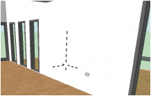
O comando Definir Vista 3D permite definir uma vista 3D precisa, em ângulo, altura e perspectiva pré-determinadas. Normalmente este comando é utilizado a partir da vista Topo/Planta 2D, mas ele também pode ser utilizado a partir de qualquer vista 3D.
Para definir uma vista 3D:
1.Selecione Visualizar > Definir Vista 3D.
2. Clique no desenho para definir a linha de observação; o ponto inicial da linha indica a posição do observador e o ponto final do ponto observado (alvo).
A janela de diálogo Definir Vista 3D irá abrir.
► Clique para exibir/ocultar parâmetros.
~~~~~~~~~~~~~~~~~~~~~~~~~
 Rotating
the Plan
Rotating
the PlanCommand |
Path |
View bar |
|---|---|---|
Rotate Plan |
View |
|
In a design layer, the view may need to be rotated to match a drawing angle. When the plan is rotated, the view switches to Rotated Top/Plan, and all existing layers are rotated together.
To rotate the plan:
1 Select the command or click the View bar button.
2 Click to indicate the center of plan rotation, and then click again to indicate the angle of plan rotation. The angle snaps to existing objects.
The temporary reference line indicates the line that will become horizontal after the operation. The temporary arrow within the arc indicates the direction of the rotation. The rotation is referenced to a horizontal line, unlike the Rotate tool.
The angle of plan rotation can also be specified from the floating data bar, or entered directly in the View bar. The drawing rotates around plan center (0, 0) when the angle is specified in the View bar.
3 All layers in the drawing rotate to match the specified angle. (If some layers were in a 3D view, they will lose this view since all layers in the drawing are set to Rotated Top/Plan; confirm that this is the desired action.) Symbols placed and objects drawn while in this view match the current rotation angle.
At the bottom left of the drawing window, the position of the X - Y axis indicator shows the drawing rotation angle and direction.
To disable the rotation animation, see Aba Interatividade.
The View bar indicates that the drawing has been rotated; the icon next to the layers in the Layers list changes, and the Current View list displays Rotated Top/Plan. If you switch to another view and want to return to the rotated top/plan view, select Rotated Top/Plan from the Current View list on the View bar.
In addition, in a Rotated Top/Plan view, the rulers display in a blue color, and the Object Info palette for objects in rotated plan displays both global world coordinates and rotated plan coordinates (depending on the Object Info palette preference).

The display of the Object Info palette coordinates in rotated plan view is controlled by a preference, accessed from the Coordinate/IFC menu at the top right corner of the Object Info palette:
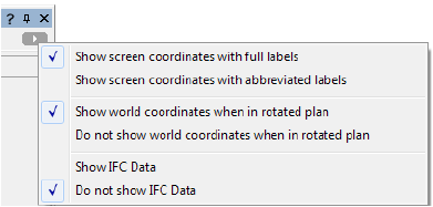
► Click to show/hide the preferences.
Once the drawing has been rotated, a different rotation angle can be specified with Rotate Plan in the View bar.
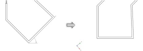
The green reference line indicates the unrotated, horizontal direction. If the Rotate Plan command is selected again, match this reference line to un-rotate the view, returning to the world coordinate system. Alternatively, to un-rotate the view, select View > Standard Views > Top/Plan, select Top/Plan from the View bar, or enter an angle of 0 for Rotate Plan in the View bar.
In rotated plan view, a working plane is automatically present, with its origin at the rotated plan pivot point and its X’ axis horizontal to the screen. Click the X’ or Y’ axis to drag the working plane to a new location. The X’ and Y’ coordinates adjust from this point and the local coordinates are reflected on the rulers.

An elevation view can be easily set based on the working
plane position. Click Working Plane Views  from the View bar, and then
select a standard view such as Front. To return to the rotated 2D view,
select Rotated Top/Plan from the Current View list
on the View bar.
from the View bar, and then
select a standard view such as Front. To return to the rotated 2D view,
select Rotated Top/Plan from the Current View list
on the View bar.
The plan rotation can be saved as a view and restored later by selecting the view for display. Select Save View Orientation in the Save View dialog box to save the plan rotation (see Creating Saved Views).
Saved views with rotation information display with a rotated icon in the View column of the Organization dialog box. Sorting by the View column separates non-rotated views from the rotated views.
~~~~~~~~~~~~~~~~~~~~~~~~~
Comando |
Path |
|---|---|
Recorte Cúbico |
View |
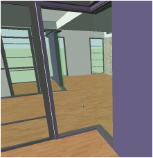
O comando Recorte Cúbico permite recortar temporariamente partes de um modelo 3D para que você possa ver o trabalho por dentro do modelo. Somente os objetos dentro do cubo estarão visíveis e serão atraídos. Isto facilita a localização de pontos de atração ou a exibição de uma área de interesse em um modelo 3D grande.
O recurso de recorte cúbico funciona somente nos modos aramado e OpenGL. Selecione os objetos que você deseja visualizar, e então escolha o comando Recorte Cúbico para criar um cubo que contenha estes objetos. Depois de criar o cubo, use a ferramenta Seleção para empurrar ou puxar as faces do cubo e ajustar seu tamanho. Use o quadro de edição do cubo para rotacioná-lo ou arrastá-lo para outra posição.
Para alinhar o plano de trabalho com a face realçada de um recorte cúbico, clique com o botão direito do mouse em uma face realçada horizontal ou vertical do cubo de clipe e selecione Definir Plano de Trabalho no menu de contexto.
Para usar o recurso Recorte Cúbico:
1.Em uma vista 3D selecione os objetos que deverão aparecer dentro do cubo. (Se nenhum objeto for selecionado, o cubo irá considerar todos os objetos atualmente visíveis.)
2.Mude o modo de apresentação para Aramado ou OpenGL.
3. Selecione Visualizar > Recorte Cúbico.
Se preferir, adicione o atalho para o comando Recorte Cúbico à barra Ferramentas. Veja “Definindo as Preferências Rápidas” na página 60.
A vista é cortada para mostrar apenas a área do modelo que contém os objetos selecionados; os objetos são rodeados por um cubo transparente. Por padrão, as áreas de seção transversal de objetos sólidos são exibidos em vermelho, conforme o plano onde o recorte cúbico faz o corte
4 Para alterar o recorte cúbico clique no canto do cubo usando a ferramenta Seleção. Um quadro de edição com os eixos X, Y e Z será exibido na face inferior. Durante a edição a vista mudará para exibir os objetos dentro do cubo.
Ação |
Descrição |
|---|---|
Para ajustar as dimensões do cubo |
Assim como na ferramenta Empurra/Puxa, a face do cubo será destacada quando o cursor estiver sobre ele. Clique em uma face e arraste-a conforme necessário. Clique novamente para definir a nova posição. |
Para rotacionar o cubo |
Clique em uma das quatro alças de rotação nos cantos do quadro de edição da face inferior do recorte cúbico. Arraste para rotacionar o cubo, e então clique para definir a nova posição. |
Para mover o cubo |
Clique na alça de movimentação no centro do quadro de edição. Arraste para mover o cubo, e então clique para definir a nova posição. |
5 Edite os objetos dentro do cubo conforme necessário. Tenha em mente o seguinte:
• Se você editar um símbolo o recorte cúbico será redefinido para o limite do símbolo. Ao sair do modo de edição de símbolos, o cubo voltará ao seu limite original.
• Enquanto o recorte cúbico estiver ativado você poderá criar um cubo diferente em cada camada de projeto. No entanto se a opção de vista unificada estiver ativada (requer Vectorworks Design Series) somente um recorte cúbico poderá ser criado.
• Ao empurrar/puxar a face do recorte cúbico, o valor da barra de dados flutuante sempre mostra a distância relativa do local do cubo do clipe original.
6 Para salvar o recorte cúbico atual e utilizá-lo posteriormente, clique em Vista > Salvar Vista, e então selecione a opção **Save View Orientation** (veja Creating Saved Views).
7.Selecione o comando Recorte Cúbico novamente para desativar o recurte cúbico e voltar à visualização completa em todas as camadas de projeto.
(Uma marca próxima ao comando Recorte Cúbico indica que o recurso está ativado.)
Se você segurar a tecla Ctrl (Windows) ou Command (Macintosh) ao ativar o comando Recorte Cúbico, o último recorte cúbico usado na camada de projeto será restaurado.


 Criando
uma Viewport de Seção a Partir de um Recorte Cúbico
Criando
uma Viewport de Seção a Partir de um Recorte CúbicoComando |
Path |
|---|---|
• Create Section Viewport • Create Horizontal Section Viewport |
Context menu |
Depois de criar um recorte cúbico, selecione a ferramenta Seleção e, em seguida clique com o botão direito (Windows) ou Ctrl+clique (Mac) uma face horizontal ou vertical destacada do recorte cúbico.
Selecione Criar Viewport de Seção no menu de contexto. A caixa de diálogo Criar Viewport de Seção abrirá.
Crie um viewport ou em uma camada camada de folha ou camada de projeto, conforme descrito nos seguintes tópicos:
• Creating a Vertical Section Viewport
• Creating a Horizontal Section Viewport
Se a classe de atributos da janela de exibição estiver definida como Advanced Section Viewport Properties, as áreas de seção cruzada serão mostradas com preenchimento preto por padrão. Alternativamente, exibe as áreas das secções transversais com os objetos originais e atributos. Na paleta Informações do Objeto, acesse a janela Propriedades Avançadas. Na guia Atributos, selecione Seções Transversais Separadas e Usar Atributos de Objetos originais.


|
Clique aqui uma uma díca em vídeo sobre este tópico (requer acesso à internet) |
~~~~~~~~~~~~~~~~~~~~~~~~~
Ferramenta |
Conjutno de Ferramentas |
|---|---|
Camera Renderworks |
Visualização |
O produto Renderworks contém um método de definir uma vista de câmera com a ferramenta Câmara Renderworks. Esta ferramenta permite ativar uma câmera particular, o que torna fácil a mudança de uma vista. Atributos específicos, como distância focal da câmera, campo de visão, altura e proporção podem ser definidos, assim como os efeitos da câmera do Renderworks, como profundidade de campo, exposição, bloom, vinheta e aberração cromática ao renderizar no Final Quality Renderworks ou Custom Renderworks renderiza modos.
Vários recursos predefinidos da câmera do Renderworks, com configurações para efeitos como luz do dia ou luz baixa interna, estão disponíveis nas Bibliotecas do Vectorworks no Administrador de Recursos.
|
Clique aqui uma uma díca em vídeo sobre este tópico (requer acesso à internet) |

Para inserir uma câmera Renderworks:
1 Selecione a ferramenta Câmara Renderworks do conjunto de ferramenta de visualização.
2 Clique na camada de projeto para especificar a localização da câmera. Clique novamente para indicar que a câmara olhar a ponto.
Se esta é a primeira vez que um objeto de câmera foi inserida nesta sessão, a caixa de diálogo Propriedades do Objeto Câmera Renderworks é aberto. Clique em OK.
3 As propriedades da câmera pode ser editado na paleta Informações do Objeto.
Você pode criar seus próprios recursos de câmera predefinidos para uso posterior através da conversão de uma câmera para um símbolo com o Converter para Grupo selecionado na caixa de diálogo Criar Símbolo (veja Criando Definições de Símbolos). Na inserção, o símbolo é desagrupada e inserido como um objeto Câmera Renderworks que pode ser modificada, se necessário.
► Clique para exibir/ocultar parâmetros.
|
Clique aqui uma uma díca em vídeo sobre este tópico (requer acesso à internet) |
~~~~~~~~~~~~~~~~~~~~~~~~~
Os ajustes da visão da câmera podem ser ajustados em detalhes em tempo-real, e atributos de visualização podem ser especificados.
Para ajustar a vista da câmera:
1.Clique em Ajuste Fino da Visão da Câmera na Paleta Info de Objetos de uma câmera.
A janela de Controles de Vista Perspectiva abrirá. Use os botões deslizantes ou entre valores para ajustar os parâmetros da câmera; mudanças são refletidas automaticamente no desenho. Mudanças são mais fáceis de visualizar durante os ajustes quando o modo de apresentação estiver em Aramado ou OpenGL.
Para Altura da Câmera, Altura Ponto Observado e Distância da Câmera, o curso do botão deslizante é proporcional ao valor mostrado. Para expandir o curso do botão deslizante, entre um valor maior.
► Clique para exibir/ocultar parâmetros.
2 Um objeto câmera pode ser copiado para adicionar vistas adicionais de câmera. Adicionalmente, os atributos de visão 2D da câmera podem ser ajustados de acordo com os atributos de cores principal e de fundo de preenchimento e traço da Paleta de Atributos. Pontos de controle ajustam o ângulo de visão, o ponto observado (alvo), e a localização do nome da câmera.

Atributo de Cor de Preenchimento/Traço |
Parâmetro |
|---|---|
Preenchimento Principal |
Define a cor do ângulo do campo de visão quando a altura da câmera é maior que a altura do ponto observado. |
Cor de Fundo de Preenchimento |
Define a cor de texto do nome da câmera |
Cor Principal de Traço |
Define a cor da linha de campo de visão conectando a câmera ao ponto observado, assim como a cor da representação 3D da câmera. |
Cor de Fundo de Traço |
Define a cor do ângulo das linhas de visão |
A divergência entre o ângulo do campo de visão aparente e o ângulo do campo de visão da lente aumentará assim que a diferença entre a altura da câmera e a altura do ponto observado aumentarem. Quando as alturas da câmera e do ponto observado são iguais, as linhas do ângulo do campo de visão da lente (cinza tracejada por default) não serão visíveis.
~~~~~~~~~~~~~~~~~~~~~~~~~
Comando |
Path |
|---|---|
Create Viewport |
View |
O viewport da camada de folha pode ser controlado por uma câmera do Renderworks. Defina a vista usando a câmera do Renderworks na camada de projeto, e em seguida crie o viewport da camada de folha conectada à câmera. A vista da câmera pode ser então editada a partir do viewport.
As câneras Renderworks não podem ser associadas a viewports de secção.
Para conectar uma câmera do Renderworks a um viewport de camada de folha:
1.Crie e ajuste a câmera do Renderworks conforme descrito em “Definindo uma Vista de Câmera no Renderworks” na página 1171. A câmera conectada ao viewport pode utilizar projeção em perspectvia ou ortogonal.
2.Selecione a câmera do Renderworks e clique em Visualizar > Criar Viewport.
3.Uma janela de diálogo confirmará se a câmera deve ser utilizada para a vista da viewport. Clique em Sim (clique em Sempre Tomar a Ação Selecionada para sempre usar a câmera do Renderworks para a vista ao criar viewports).
1 A janela Criar Viewport é exibida. Informe um nome para a viewport e o título do desenho, e selecione a camada de folha onde você deseja colocá-la. Os parâmetros da vista e da projeção são definidos pela câmera e por isso permanecem desativados. O modo de apresentação da câmera não afeta o modo de apresentação da viewport. Altere os outros parâmetros conforme necessário (veja Creating a Sheet Layer Viewport from a Design Layer).
O viewport é criada na camada de folha especificada, com a vista, a projeção e a distância de perspectiva copiadas da câmera do Renderworks. Na paleta Informações de Objeto, o item Câmera RW é alterado para Sim.
A câmera torna-se parte da viewport e pode ser editada (ou excluída), ou você pode alterar os parâmetros da vista do viewport alterando-a através do viewport. Uma viewport de camada de folha existente também pode ser conectada a uma câmera do Renderworks. Veja Editing a Linked Renderworks Camera.
|
Clique aqui uma uma díca em vídeo sobre este tópico (requer acesso à internet) |
~~~~~~~~~~~~~~~~~~~~~~~~~
Câmera Match define a vista 3D de um modelo para corresponder à vista em perspectiva de uma determinada fotografia, colocando com precisão a fotografia no modelo. A visão é determinada por:
• A background image (photograph)
• A Camera Match reference
• A Camera Match object
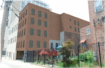
Camera Match consists of the following commands and tools:
Item |
Descrição |
|---|---|
Place Reference command |
Inserted on a design layer, the Camera Match reference provides Camera Match with the model’s orientation in 3D space. |
Place Camera Match Object command |
Placed while in viewport Edit Annotation mode, the Camera Match object calculates the 3D view by aligning control lines to the photograph. |
Camera Match Mask tool |
Placed while in viewport Edit Annotation mode, the Camera Match mask object masks parts of the rendered model with the photo image, effectively erasing portions of the rendered model. Mask objects can also be used to clone parts of the photo; cloning can cover parts of the photo image with other parts of the photo. |
Camera Match Shadow tool |
Placed while in viewport Edit Annotation mode, the Camera Match shadow object adds shadows and shading to the rendered model |
~~~~~~~~~~~~~~~~~~~~~~~~~
Special considerations apply when selecting the photo image to use with Camera Match tools and commands.
• It is best to start with a photo image that is the same size and resolution as desired for the final composite image.
• When taking photos of a site, do not use special lenses that straighten perspective views or distort the image. Such lenses create images that are impossible to match.
• Avoid taking photos head on, where the camera is pointing perfectly straight down the center of a corridor, or exactly perpendicular to the face of a building. When setting up control lines in Camera Match, if a pair of control lines become extremely close to parallel, the calculated view may be prone to errors. Similarly, when a vanishing point is extremely near center of the photo (when taken), the calculated view may have errors. If you require a photo like this, take several photos from slightly varying angles. This will provide some back up options if your first choice has difficulty.
• Include the scope of project when you take the photo. All of the proposed parts of the model that you wish to show should fit within the photo. This may seem obvious, but it is easy to overlook when you are on site with only the existing conditions.
• Most lenses create some degree of barrel distortion in their images. This lens distortion causes straight lines (or edges) in the photo to look curved, providing less accurate results. This lens distortion should be corrected, on an uncropped and unaltered version of the image file. Some popular image editing applications have tools for this, but there are also some low cost applications that are designed specifically for this purpose, such as PTLens.
~~~~~~~~~~~~~~~~~~~~~~~~~
Command |
Path |
|---|---|
Place Reference |
View > Camera Match |
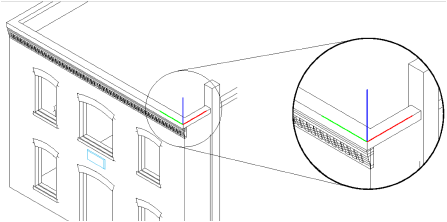
The Camera Match reference provides Camera Match with the model’s orientation in 3D space. It is positioned on the model to define the planes where the vanishing lines lie. The three color-coded axes define the following vanishing points:
• Green: Left vanishing point
• Red: Right vanishing point
• Blue: Vertical vanishing point
The Camera Match reference also establishes a 3D point that can be located in the photo (an existing point at a known height).
Typically, the Camera Match reference should be located at a corner of an object and the two arrows should point along two nonparallel vertical planes (such as two walls that meet at a corner). If the corner angle of the model is not 90 degrees, the angle between left and right axes can be adjusted to match. In Top/Plan view, drag the selection handle at the endpoint of each line to align with the corner of the model.
To place a Camera Match reference:
1 Navigate to the design layer that contains the 3D model.
2 Select the command.
3 Name the Camera Match reference.
4 Click once on the desired point of reference in the model, rotate the Camera Match reference to relate to the model, and then click again.
The properties of a selected Camera Match reference can be edited from the Object Info palette.
► Clique para exibir/ocultar parâmetros.
~~~~~~~~~~~~~~~~~~~~~~~~~
The Camera Match object is designed to be used while in a viewport’s Edit Annotation mode.
Create a sheet layer viewport as described in Creating Sheet Layer Viewports and place it on a new (or empty) sheet layer. Using viewport overrides, display the desired layers and classes. The viewport should have a solid fill from the Attributes palette.
To make the Camera Match process faster, display only minimal geometry in the viewport to represent the existing model. Once the view is set, change the visibility settings to display what is needed for the final rendering.
~~~~~~~~~~~~~~~~~~~~~~~~~
Command |
Path |
|---|---|
Place Camera Match Object |
View > Camera Match |
The Camera Match object contains the photo, controls, and target reference for manipulation; it is inserted into the drawing by placing it in the sheet layer viewport while in Edit Annotation mode.
To place a Camera Match object:
1 Right-click on the sheet layer viewport and select Edit Annotations from the context menu. See Creating Annotations for Sheet Layer Viewports.
2 Select the command.
The Camera Match Settings dialog box opens.
► Clique para exibir/ocultar parâmetros.
3 Select a photo from the current file, or click Import New Image to import a new photo image as described in Importando Arquivos de Imagem.
4 Select the Camera Match reference from the Reference Object list, and select the line style to use for the extension lines.
A Camera Match object is placed in the viewport annotation. The properties of the Camera Match object can be edited from the Object Info palette.
► Clique para exibir/ocultar parâmetros.
~~~~~~~~~~~~~~~~~~~~~~~~~
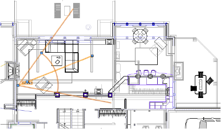
A preview object contained within the Camera Match object helps establish the Camera Match view. This object is made up of two vertical planes placed in relation to the reference object. One vertical plane is green and vanishes toward the left vanish point; the other plane is red and vanishes toward the right vanish point. This object always displays in the perspective view calculated by the Camera Match object, according to its current settings. This provides a live preview as adjustments are made, making it easier to set the Parâmetros and control lines accurately.
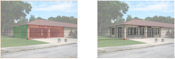
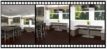
While the default settings may not relate to the size of objects in the photo, they can be used to get a good feel for how the perspective view is shaping up as control lines and settings are changed in the Camera Match object. However, if you know the size of an existing object in the photo, the Preview Object can be set to this size. In the image, the preview object was set to the dimensions from the corner to two columns wide and two columns deep. This also happens to be the extents of the proposed parts of the model. You can see just how well the view is aligning with the photo before actually clicking Set View to Match. Keep in mind that the preview object is only an aid to help with setting the Parâmetros of the Camera Match object. While it is good to try to set up the Camera Match object so that the preview object aligns well with the photo, it is not critical to align it perfectly. Once it is close, click Set View to Match. You can always tune the view to further refine it.
When you click Set View to Match (or Fine Tune View), the preview object is turned off and the model view is set (as shown in the image to the right).
To set the preview object Parâmetros:
1 Select the Camera Match object (in the Edit Annotation mode of the sheet layer viewport).
2 Click Preview Object Settings from the Object Info palette.
The Preview Object Settings dialog box opens.
► Clique para exibir/ocultar parâmetros.
~~~~~~~~~~~~~~~~~~~~~~~~~
The size of the photo image in the Camera Match object must be set appropriately.
To set the photo size:
1 Select the Camera Match object.
2 In the Object Info palette, set the Photo Printed Width or Photo Printed Height to the desired size for the rendering.
For the final rendering, it is recommended to set the sheet layer’s Raster Rendering DPI value in Setting Sheet Layer Properties to match the Sug. Sheet Layer DPI displayed in the Object Info palette of the Camera Match object, or to the desired resolution for final output.
~~~~~~~~~~~~~~~~~~~~~~~~~
A total of six control lines define the three vanishing points of a photo.

Each control line, along with the reference target, serves to correctly place and orient the photo image.
Item |
Purpose |
|---|---|
Green and red control lines |
The green and red lines establish the left and right vanishing points respectively |
Blue control lines |
The blue lines establish the vertical vanishing point |
Measured Line |
The measured line is a control line that specifies the known length of a feature in the photo. Any control line that lies on he vertical plane defined by the green or red axis of the Camera Match reference can be selected as the measured line. The control line that is chosen as the measured line is shown with a bold arrow and displays its given dimension |
Reference Target Point |
The reference target point establishes where the Camera Match reference is on the photo. The reference target point is indicated by a circle with crosshairs; the color of the target corresponds to the color of the measured line. The reference target point (and the Camera Match reference) should lie on the vertical plane defined by the measured line. |
Horizon Line |
The black line represents the calculated horizon line |

The measured line represents a known length within the photo image.
To select the measured line and specify its length:
1 With only the Camera Match object selected, select View > Zoom > Fit to Objects so that the entire photo is within the drawing window.
2 Position the control lines so that Camera Match can identify the orientation of the Camera Match reference:
• The green lines point toward the left vanishing point (defined by the green axis of the Camera Match reference).
• The red lines point toward the right vanishing point (defined by the red axis of the Camera Match reference).
• The blue lines point toward the vertical vanishing point. Place on any vertical element in the photo.
3 From the Object Info palette, select the Measured Line from the list, and then enter the Measured Length of the line.
4 Since the reference target point establishes where the Camera Match reference is on the photo, use the reference target’s control point to move it to the location of the Camera Match reference on the photo.
Initially, the Camera Match object displays with the six colored control lines and a reference target.

The reference target is the circle with cross-hairs. Move it to the Camera Match reference location on the photo.
Before adjusting the control lines and target, turn off all constraints in the Snapping palette. This makes it easier to place the points and adjust the lines without inadvertently snapping to objects in the model.
Each control line has handles for adjusting its location. Move the control lines so that the green lines point toward the left vanishing point, the red lines toward the right, and the blue lines toward the vertical. Once the control lines are in place, zoom in on each control line to fine tune it.
Try to keep each colored pair of lines far from one another. The closer any pair of lines are, the more nearly parallel they become; this makes it harder to establish an accurate vanishing point.
Colored pairs of control lines that are close to parallel are far more sensitive to adjustments. When like color control lines are near parallel, even a very minute change in the angle between them can cause a very large change in the location of the vanishing point where they converge. When setting up views in this situation, the preview object can be a big help in seeing the effect while making very small changes to the control lines (see The Camera Match Preview Object). If you cannot get the preview object perfectly placed, get it as close as you can, set the view, then fine tune it to get it where you need.

In the image, the two red lines are not ideal, but (as evident in the preview object) they are still acceptable.
~~~~~~~~~~~~~~~~~~~~~~~~~
Once the control lines are in place, Camera Match sets the view of the viewport to match.
Setting the view to match performs the following operations:
• If needed, a Renderworks background is created from the photo image and set to be used by the viewport.
• The view is set according to the control lines.
• The Camera Match reference (from the model) is anchored to the reference target location in the photo.
To set the view to match:
1 Select the Camera Match object.
2 From the Tuning Render list in the Object Info palette, select Wireframe or Hidden Line.
The Render Mode pop-up will set the render mode for the viewport when setting views with the Camera Match object. Wireframe or Hidden Line mode is recommended for initially setting and tuning the view.
3 Click Set View to Match.
If the model is upside down after clicking Set View to Match, the green and red control lines are probably pointing to the incorrect vanishing points. The green control lines must point to the left vanishing point, and the red control lines must point to the right vanishing point.
~~~~~~~~~~~~~~~~~~~~~~~~~
If the control lines are accurately placed, the calculated view may be close enough for your needs. However, it is still likely that the view will need fine tuning. Fine Tune View controls adjust the view while keeping the Camera Match reference anchored to the reference target in the photo.
To fine tune the view:
1 Select the Camera Match object.
2 Click Fine Tune View from the Object Info palette.
The Fine Tune View dialog box opens, with a series of control buttons across the top. Each control button, when clicked, controls the slider. Dragging the slider adjusts the view according to the chosen control. When the slider is being dragged (with the mouse button held down), the view updates. When the slider is released, the slider control re-centers itself, allowing for further adjustments.
Start tuning with the vanishing point controls; if needed, continue tuning with the rotate/distance controls.
► Clique para exibir/ocultar parâmetros.
3 When the fine tune view is complete, click Save to set the Camera Match view to the fine tuned settings and close the Fine Tune View dialog box.
~~~~~~~~~~~~~~~~~~~~~~~~~
Tool |
Tool set |
|---|---|
Camera Match Mask
|
Visualization |
Masking can hide parts of a rendered model that should be behind objects in the photo image. While complex masking (for example, hiding many tree branches) may be best left to an image editing application, much can be done directly in the Vectorworks program using Camera Match masks. Masks also allow clones to be created, scaled, and rotated, for better blending.
While a mask object can be placed over the model in one step, it can be difficult to see the parts of the photo where you want the mask. However, you can first create a temporary mask object, allowing the desired parts of the photo to be seen.

Mode |
Descrição |
|---|---|
Polyline creation options |
Specifies the method for drawing the polyline shape for the mask |
Fillet Radius |
Sets the fillet radius when the Arc Vertex mode is selected |
Preferences |
Opens the object properties dialog box to set the default preferences for camera match masks |
To create a Camera Match mask:
1 Render the Camera Match view and crop the viewport if needed.
2 While in the viewport Edit Annotation mode, click the tool, and roughly draw a polyline object over the area of the model to be masked.

3 Once drawn, the mask object brings the parts of the photo that it contains to the front of the model. Now the parts of the photo that need to be worked on can be seen. This mask is temporary and is deleted after the final mask is placed.
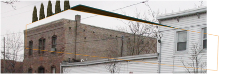
4 Using the Camera Match Mask tool, draw another polyline only over the parts of the photo that need to be in front of the model.

5 After drawing the polyline, the final Camera Match mask object is created. Delete the temporary mask and examine the results. If needed, double-click on the mask to enter Edit Point mode. While in this mode, individual points can be moved, added, or deleted.
The settings of a selected Camera Match mask can be edited from the Object Info palette.
► Clique para exibir/ocultar parâmetros.
Tool |
Tool set |
|---|---|
Camera Match Mask
|
Visualization |
To clone an area with a Camera Match mask:
1 As previously described, use the tool to place a mask over the desired area for the cloned image.
2 Select the mask object. Select Clone Mode from the Object Info palette.
A handle is placed on the mask object.
When the mask object is selected, a dashed outline highlight also appears at the grip location. This indicates the area of the photo used for the clone.
3 Move the handle to an area in the image to clone; that part of the photo appears within the mask object.

~~~~~~~~~~~~~~~~~~~~~~~~~
The following is an illustrated example of how a Camera Match mask’s cloning features can be used. In this example, an existing window in the photo image is removed by placing a mask object over it and cloning the wall brick pattern from the wall.

~~~~~~~~~~~~~~~~~~~~~~~~~
The following example illustrates the Camera Match mask’s Line Mode. In this example, a mask object brings a power line from the photo image in front of the rendered model.

~~~~~~~~~~~~~~~~~~~~~~~~~
Tool |
Tool set |
|---|---|
Camera Match Shadow
|
Visualization |
Shadows and shading can be added to the rendering with the Camera Match Shadow tool.

Mode |
Descrição |
|---|---|
Polyline creation options |
Specifies the method for drawing the polyline shape for the shadow |
Fillet Radius |
Sets the fillet radius when the Arc Vertex mode is selected |
Preferences |
Opens the object properties dialog box to set the default preferences for camera match shadows |
To place a Camera Match shadow:
1 While in the viewport Edit Annotation mode, click the tool.
2 Draw a polyline object over the area of the model that needs a shadow.


The settings of a selected Camera Match shadow can be edited from the Object Info palette.
► Clique para exibir/ocultar parâmetros.
~~~~~~~~~~~~~~~~~~~~~~~~~
Exported web views provide an interactive 3D viewing experience suitable for sharing with clients, team members, and others. They can be viewed in orbit mode or first person mode from any internet-connected device. Head-mounted displays (HMD) and mobile devices equipped with orientation and motion sensors also allow immersive 360° views of the model. Please see the Vectorworks Forum for tips on configuring compatible HMDs for web views.
Click the link provided by the web view author to display the web view in your default browser.
Files saved locally do not open correctly in the Google Chrome, Microsoft Internet Explorer, or Microsoft Edge browsers because of unavoidable security issues with the browsers. To view the web view from a folder on your local drive, open the index.html file using a different browser. Firefox and Safari (on Mac) are recommended.
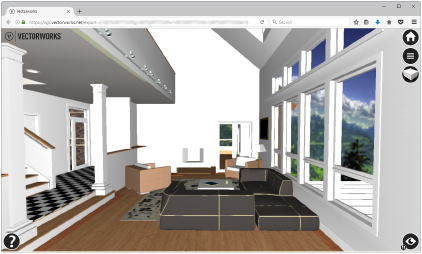
Controller |
Descrição |
|---|---|
Reset
|
Click/tap to return to the initial view and Orbit mode |
First Person Options
|
Click/tap to set options for controlling First Person mode: • whether to walk through walls (collision detection) • walking speed • rotation sensitivity • shadow display options including the angle of directional light • display the model statistics |
Clip Cube
|
Click/tap to toggle the interactive clip cube on/off to crop the web view; the icon displays with a red face to indicate that the clip cube is on. See Exibindo um Modelo no Recorte Cúbico. First-Person mode and the clip cube cannot be active at the same time. After turning off the clip cube, click/tap Reset to restore the view. |
Select Camera Controller
|
Click/tap to toggle the viewing mode; the currently active mode displays on the bottom left of this icon |
Orbit mode
|
Rotate, pan, and zoom to view the model; you can move through walls, floors, and other solid objects |
First-Person mode
|
“Walk” through the model; the Walk Through Walls setting in First Person Options determines whether you bump into walls and other solid objects as in a video game, or can walk through them. Click/tap a surface in the model to teleport to that location when accessing First-Person mode. |
360° mode (mobile only)
|
For mobile devices equipped with orientation and motion sensors, tap to activate a 360° view controlled by the motion of the device. In 360° mode, the model does not respond to screen taps and drags. |
VR mode (accessible with a head-mounted display or from 360° mode on a mobile device)
|
If a head-mounted display or a virtual reality viewer is used, click/tap to activate VR mode. For mobile devices, select the supported viewer to use, and place your device into the viewer for an immersive experience. The view does not respond to touch events when in VR mode. To enable VR “walk-through” in First Person mode, the person must be on a surface before accessing VR mode. |
Help
|
Click/tap to display context-sensitive help |
Because many clients and others who receive exported web views do not have access to the Vectorworks help system, and because navigation varies depending on which device is used, the web view itself contains a brief introductory tutorial and more detailed device-specific help.
|
Clique aqui uma uma díca em vídeo sobre este tópico (requer acesso à internet) |
~~~~~~~~~~~~~~~~~~~~~~~~~


