Apresentando o Projeto
Viewports podem exibir vistas inteiras, bem como recortadas, de um desenho, com configurações especificadas de visibilidade de camada e classe, projeção, modo de renderização e parâmetros de orientação (completos com detalhes, anotações, dimensões e bordas de bloco de título). Viewports podem mostrar outras partes do documento ativo ou até partes de outros documentos. Se o desenho mudar, atualize as viewports para refletir as alterações.
Existem vários tipos diferentes de viewports, dependendo se você possui o produto Vectorworks Fundamentals ou um ou mais produtos Vectorworks Design Series.
In both the Vectorworks Fundamentals and Vectorworks Design Series products, you can create one or more viewports on a sheet layer, and each viewport can show one or more design layers from this document. Sheet layer viewports, often created for presentation purposes, are created on special layers called sheet layers. Sheet layers retain their own print settings, including print area, resolution, and printer setup Parâmetros. For more information on sheet layers, see Criando Camdas. A sheet layer viewport can also be linked to a Renderworks camera.
Vectorworks Design Series products allow you to create one or more viewports on a design layer, and the design layers shown in the viewports can be either from the current document, or referenced from another document. Like a sheet layer viewport, a design layer viewport can display design layers from the current file in a full or cropped view; unlike a sheet layer viewport, it can include one or more design layers that are referenced from another file.
A section viewport creates a cross section view of a model, but leaves the model intact. A section viewport can be created from a design layer, another non-sectioned viewport, a clip cube on a design layer, or from a section line or section-elevation marker in the drawing. It can be placed on a design layer or sheet layer. Both vertical and horizontal section viewports can be created. Horizontal section viewports give the ability to set different display options and attributes for certain objects by class or individually.
Interior elevation viewports are section viewports that allow you to simultaneously create as many as four interior elevation viewports from a selected room or area of the model. An interior-elevation marker automatically placed on the design layer allows you to edit which views you display and maintains coordination between the drawing and the viewports. These viewports can be placed on either a design layer or a sheet layer.
A detail viewport is a cropped sheet layer viewport that shows a detail view of any part of a drawing. A detail viewport can be created from a design layer, another sheet layer viewport, or a section viewport. The crop object used to create the detail viewport becomes a callout object that is linked to the detail viewport for easy navigation between layers.
The Viewports tab of the Organization dialog box differentiates among the various types of viewports.

|
Clique aqui para uma dica em vídeo sobre este tópico (requer acesso a internet) |
~~~~~~~~~~~~~~~~~~~~~~~~~
Comando |
Path |
|---|---|
Create Viewport |
View |
To create a viewport from a design layer:
1 Select the Comando.
The Create Viewport dialog box opens. The viewport Parâmetros are initially set to be the same as those of the design layer that is currently active, but they can be changed here. After the viewport has been created, additional Parâmetros become available; see Viewport Properties.
For Vectorworks Design Series products, the Create Viewport dialog box has additional functionality for creating design layer viewports; see Creating a Design Layer Viewport from an Internal Design Layer.
► Clique para exibir/ocultar parâmetros.
2 Enter the desired Parâmetros and click OK.
3 If a sheet layer does not already exist in the file, the New Sheet Layer dialog box opens automatically to create one.
The viewport is created on the designated sheet layer, and the sheet layer becomes active.
~~~~~~~~~~~~~~~~~~~~~~~~~
Comando |
Path |
|---|---|
Create Viewport |
View |
To create a cropped viewport either from a design layer or from an existing uncropped viewport on a sheet layer:
1 Activate the existing design layer or sheet layer that will display in the viewport.
2 Create a 2D object such as a rectangle, circle, or polyline. The 2D object must define an area; for example, a 2D line cannot be used. Crop objects are automatically placed in the screen plane (see Planar Modes of 2D Objects: Screen Plane and Layer Plane). Position the 2D object on the design layer or existing uncropped viewport to delimit the area to be included in the new viewport. The fill of a viewport cropping object is always None; however, the pen style can be set from the Attributes palette.
3 If the cropped viewport is being created from a design layer, select the 2D object. If the cropped viewport is being created from a sheet layer, select both the 2D object and the uncropped viewport.
4 Select the Comando.
5 An alert dialog box asks whether the object should be used as the viewport’s crop. Click Yes (click Always do the selected action to always use a selected 2D object as a crop object when creating viewports).
6 The Create Viewport dialog box opens. Enter a viewport name and drawing title, and select the sheet layer to place it on. The remaining viewport Parâmetros are initially set to be the same as the design layer properties (for design layers) or selected viewport (for sheet layers). Change the Parâmetros as needed.
The viewport, cropped by the selected 2D object, is created on the specified sheet layer.
7 By default, the crop object is not visible. To change the visibility of the crop object, select the viewport and click Crop Visible from the Object Info palette.

~~~~~~~~~~~~~~~~~~~~~~~~~
 Creating Multiple
Viewports Simultaneously
Creating Multiple
Viewports SimultaneouslyComando |
Path |
|---|---|
Create Multiple Viewports |
View |
The Create Multiple Viewports Comando generates 2D drawings from a 3D model and creates up to seven sheet layer viewports configured with several orthographic views and one isometric view of the model.
If you run the Comando from a sheet layer, the viewports are added to that sheet layer. If you run the Comando from a design layer, the viewports are added to a new sheet layer that is created automatically.
To create as many as four interior elevation viewports of the same space simultaneously, see Creating Interior Elevation Viewports.
To create multiple viewports simultaneously:
1 Select the Comando.
The Create Multiple Viewports dialog box opens.
2 Specify the desired viewport scale, views, and angle projection method.
► Clique para exibir/ocultar parâmetros.
Viewports are created at the designated layer scale, using the current layer and class visibility and print area settings, with the rendered style set to hidden line rendering. Viewports are aligned horizontally and vertically, separated by a fixed distance, and centered on the sheet layer.
3 Optionally, configure the viewports’ layer and class settings (Active, Show, or Gray Others only), annotate the viewport, or modify the rendering style or other viewport Parâmetros.
For more information, see Layer or Class Visibility Changes for Viewports and Saved Views Using Visibility Columns, Creating Annotations for Sheet Layer Viewports, and Viewport Properties.
~~~~~~~~~~~~~~~~~~~~~~~~~
 Creating Design Layer Viewports
A sheet layer viewport displays a full or cropped view of one or more design layers, which you can change without affecting the original drawing. For example, change the viewport’s layer and class visibilities, use a different render mode, or add annotations and dimensions. (See Creating Sheet Layer Viewports.)
Design layer viewports provide different functionality, for more flexibility. Like a sheet layer viewport, a design layer viewport can display design layers from the current file in a full or cropped view; unlike a sheet layer viewport, it can include one or more design layers that are referenced from another file.
Like a sheet layer viewport, in a design layer viewport you can control layer and class visibility, and create layer and class overrides. However, because it is an object on a design layer, a design layer viewport has the same view, scale, and render mode as everything else on the layer. You can use 2D and 3D drawing tools to add objects to the design layer, but you cannot add annotations to a design layer viewport.
Design layer viewports replace the layer link functionality present in the Vectorworks Fundamentals product. Current layer links can be easily converted to a design layer viewport with the Modify > Convert > Convert to Viewport Comando (Vectorworks Design Series required). (See Converting Layer Links.)
The search criteria used in worksheets and in the Script Editor allow you to filter out items from design layer viewports, to prevent unwanted duplicates in schedules.
~~~~~~~~~~~~~~~~~~~~~~~~~
 Creating
a Design Layer Viewport from an Internal Design Layer
Creating
a Design Layer Viewport from an Internal Design LayerComando |
Path |
|---|---|
Create Viewport |
View |
To create a design layer viewport that displays a design layer in the same file:
1 Select the Comando. Alternatively, from either the Organization dialog box or the Navigation palette, select the Viewports tab, and click New.
2 The Create Viewport dialog box opens. The scale, view, and render mode of the viewport are determined by the design layer on which it is placed; they cannot be changed here. Set the other viewport Parâmetros. After the viewport has been created, additional Parâmetros become available; see Modifying Viewports.
► Clique para exibir/ocultar parâmetros.
The viewport is created on the designated design layer, and the design layer becomes active. The viewport can be cropped, as described in Cropping Existing Sheet Layer or Design Layer Viewports.
~~~~~~~~~~~~~~~~~~~~~~~~~
 Creating
a Design Layer Viewport by Cropping
Creating
a Design Layer Viewport by CroppingComando |
Path |
|---|---|
Create Viewport |
View |
The viewport and the design layer that it displays must both be in the same file.
To create a design layer viewport by cropping:
1 Access the design layer that will display in the viewport.
2 Create a 2D object such as a rectangle, circle, or polyline. The 2D object must define an area; for example, a 2D line cannot be used. Crop objects are automatically placed in the screen plane (see Planar Modes of 2D Objects: Screen Plane and Layer Plane). Position the 2D object on the design layer to delimit the area to be included in the new viewport. The fill of a viewport crop object is always None; however, the pen style can be set from the Attributes palette.
3 Select the 2D crop object and then select the Comando.
4 An alert dialog box asks whether the object should be used as the viewport’s crop. Click Yes (also select Always do the selected action to always use a selected 2D object as a crop object when creating viewports).
5 The Create Viewport dialog box opens. Select the design layer on which to create the viewport. The Source must be the current document. Specify the design layers and classes to display in the viewport. (See Changing the Layer Properties of Sheet Layer or Design Layer Viewports and Changing the Class Properties of Sheet Layer or Design Layer Viewports.)
The viewport, cropped by the selected 2D object, is created on the specified design layer.
6 By default, the crop object is not visible. To change the visibility of the crop object, select the viewport and select the Crop Visible setting from the Object Info palette.

~~~~~~~~~~~~~~~~~~~~~~~~~
 Creating
a Referenced Design Layer Viewport
Creating
a Referenced Design Layer ViewportComando |
Path |
|---|---|
Create Viewport |
View |
Referencing allows you to use information from other Vectorworks files in your file, including design layers, classes, and resources (such as hatches, worksheets, or symbols). There are two ways to reference design layers that are in other Vectorworks files:
• The default method in the Vectorworks Design Series products is to create a design layer viewport and then reference the desired design layers from the master file into the viewport, as described here. One advantage to this method is that all of the layers, classes, and resources from the master file are not automatically imported into the target file.
• In the Vectorworks Fundamentals product, design layers are imported into the target file when they are referenced. For backward compatibility, the Vectorworks Design Series products support this method. See Adding and Editing Layer Import References.
A reference for a design layer viewport can be created when the viewport is created, or it can be created ahead of time from the References tab of the Organization dialog box.
To create a design layer viewport that references a design layer in another file:
1 If the current file uses layer import referencing, switch to design layer viewport referencing. (From the References tab of the Organization dialog box, click Settings, and click the Design layer viewports option from the Reference Settings dialog box. Any existing referenced layers are automatically converted into referenced design layer viewports.)
2 Select the Comando. Alternatively, from either the Organization dialog box or the Navigation palette, select the Viewports tab, and click New.
3 The Create Viewport dialog box opens. Enter a Viewport Name and Drawing Title, and then select the design layer on which to create the viewport.
4 Click Select Source to open the Select Viewport Source dialog box, and enter information about the referenced document.
► Clique para exibir/ocultar parâmetros.
5 Click OK in the Select Viewport Source dialog box to return to the Create Viewport dialog box.
6 Specify the design layers and classes to display in the viewport (see Changing the Layer Properties of Sheet Layer or Design Layer Viewports and Changing the Class Properties of Sheet Layer or Design Layer Viewports).
The viewport is created on the designated design layer, and the design layer becomes active. The viewport can be cropped, as described in Cropping Existing Sheet Layer or Design Layer Viewports.
The master file displays on the References tab of the Organization dialog box; for details about how to edit, update, or delete references, see Workgroups and Referencing.
~~~~~~~~~~~~~~~~~~~~~~~~~
 Creating Section Viewports
A section viewport creates either a vertical or horizontal cross section view of a model, but leaves the model intact. The section viewport can display a 2D cross section view of only the objects that intersect the cut plane, or, additionally, the 3D geometry that remains on the indicated side of an infinite plane passing through the model.
Create a section view from one or more design layers, from a clip cube on a design layer, or from a viewport on a sheet layer. By creating several section viewports, models can be analyzed and presented effectively. The section views can be updated as the model changes, and their attributes and appearance can be easily changed.
A section viewport can be created on either a sheet layer or a design layer; the functionality and purpose of the two types of section viewports are different.
Section viewports on sheet layers can include annotations and automatic drawing coordination of the sheet and drawing numbers; also, if there are multiple viewports on a sheet layer, each can a have different view and scale. [KB note: I think the following sentence, which was already here, must be wrong. It seems literally nonsensical to me. ???] These types of sections are always in Top/Plan view since they are on sheet layers, and are created for construction drawings. To get a 3D “look,” switch to Perspective Projection.
For sheet layer section viewports, to automatically coordinate the sheet numbers and drawing numbers among the title blocks, drawing labels, and section markers in a file, select Use Automatic Drawing Coordination in the Display tab of the Document Preferences. This feature keeps references up to date, even when drawings are edited or moved to a different layer.
Section viewports on design layers are useful when, for example, a detail section is needed in a Front rendered view. A design layer section viewport allows comparison between a section and an elevation view. In a team environment, the design layer section viewport can be referenced in other files.
In addition to the section line instance that is automatically created with a vertical section viewport, a section-elevation marker can be linked to a vertical section viewport for annotation; see Section-Elevation Marker Tool.
Interior elevation viewports are a subcategory of vertical section viewports that display as many as four elevations of a space as seen from within the room, without creating a cross section of the model; see Creating Interior Elevation Viewports.
~~~~~~~~~~~~~~~~~~~~~~~~~
 Creating
a Vertical Section Viewport
Creating
a Vertical Section ViewportComando |
Path |
|---|---|
Create Section Viewport |
• View • Context menu |
When you create a vertical section viewport, you can place it on either a sheet layer or design layer. Section viewports on sheet layers can have annotations and automatic drawing coordination of the sheet and drawing numbers; also, if there are multiple viewports on a sheet layer, each can a have different view and scale. Section viewports on design layers are useful when a detailed section is needed, or when the section viewport needs to be referenced into other files.
Create a vertical section view from a design layer, from a clip cube, or from a viewport on a sheet layer. A section viewport that is created from a design layer or clip cube can be updated when changes are made to the design layer. However, a section viewport that is created from a viewport does not maintain a connection to the viewport that created it. It updates when the design layers that are visible in the source viewport change.
To create a vertical section viewport:
1 Prepare to create the viewport as follows:
• To create a section view from an active design layer, set the layer to Top/Plan view by selecting View > Standard Views > Top/Plan.
• To create a section view from an existing viewport, select a non-sectioned viewport object. The viewport object must be in Top, Bottom, Left, Right, Front, or Back view orientation.
• To create a section view from an existing clip cube object, use the Selection tool to highlight the face of the clip cube where the section will begin. (See Viewing a Model with the Clip Cube.)
2 Do one of the following:
• Select the Comando. If you are using a clip cube, the section line is created automatically from a vertical clip cube face; skip to step 4.
• Create a section line with the Section-Elevation Marker Tool and select the Comando or click Create Section Viewport from the Object Info palette. Skip to step 4.
• Duplicate an existing section line from another viewport. The copy will maintain all the settings and attributes of the parent section line, but will not be associated with a viewport (a red unlinked icon displays at the beginning of the line). Position the line and edit its path, if needed, and then select the Comando or click Create Section Viewport from the Object Info palette. Skip to step 4.
3 Draw the section line to create the cutting plane on the design layer or viewport.
Click in the drawing and drag the mouse to begin drawing the marker line. Click to mark the end of the line, and then click to indicate the side of the line to look toward (keep), which is indicated by a black arrow. Double-click to end the line.
To create a broken section line, click in the drawing and draw the first segment. Indicate which side of the drawing to show in the viewport. Click and drag to draw additional segments; broken section line segments are always parallel or perpendicular to each other (90° angles). Double-click to end the broken line.
4 The Create Section Viewport dialog box opens. The available Parâmetros depend on whether you choose to place the section viewport on a sheet layer or design layer.
The scale of a design layer section viewport is the same as the layer where it is placed. The rendering mode of the current layer is also used to render the design layer section viewport.
► Clique para exibir/ocultar parâmetros.
A section line object is created on the layer, or is added to the annotations space of the existing non-sectioned viewport. A vertical section viewport is created on the selected layer, and the drawing switches to that layer, displaying the new section viewport.
For viewports placed on a design layer, the view is initially set to Top/Plan, but this can be changed, and the section can be displayed in any view (the Flyover tool can also be used to view the section). Additionally, there is an option to display a flattened version of the section, which can be used to create section drawings or details.
A design layer section viewport can be cropped, but it does not contain an annotation space.
~~~~~~~~~~~~~~~~~~~~~~~~~
The Section-Elevation Marker tool creates two different kinds of objects, section-elevation markers, and section lines (Design Series required), which look very similar on a drawing but have different capabilities.
• A section-elevation marker can serve as a reference line graphic for vertical sections and elevations, or as a cutting plane graphic. In Fundamentals, the section-elevation marker is simply a graphic. In Design Series products, section-elevation markers can be linked to a viewport, and can be used to create a vertical section viewport. Depending on the type of viewport it is linked to, its drawing number and sheet number are synced to the selected viewport, similar to a section line.
• A section line is used to create a vertical section viewport (horizontal sections do not have them). The section line graphically indicates the cutting plane of the section viewport and shows the orientation of the section view; section lines that are not a single straight line can have only 90° angles. To access a section line from its section viewport, click Section Line Instances from the Object Info palette (see Section Line Instances).
A section line is also automatically created when a vertical section viewport is created using the Create Section Viewport Comando.
There are several methods for Editing Section Lines and Section-Elevation Markers after placement.
Section-elevation markers and section lines that are linked to a viewport (Design Series required) display with a green link icon next to the beginning marker; unlined objects display a broken red link icon. These icons provide screen feedback only; they do not print or export. When a section viewport is deleted, the associated section line and any linked section-elevation markers are also deleted.
To create a section-elevation marker in Fundamentals:
Tool |
Tool set |
|---|---|
Section-Elevation Marker
|
Dims/Notes |
1 Click the tool and then click Preferences to set the default Parâmetros for section-elevation markers (see Section-Elevation Marker Properties).
2 Click to place one end of the section-elevation marker and move the mouse to the end point, or to insert a multi-segment marker, click to define each segment.
3 Double-click at the end point to finish placing the section-elevation marker.
To create a section-elevation marker in Design Series:
Mode |
Tool |
Tool set |
|---|---|---|
Unconstrained |
Section-Elevation Marker
|
Dims/Notes |
1 Click the tool and mode, and then click Preferences to set the default Parâmetros for section-elevation markers (see Section-Elevation Marker Properties).
2 Click to place the beginning point of the section-elevation marker.
To create a broken section-elevation marker, click in the drawing and draw the first segment. Indicate which side of the drawing to show in the viewport. Click and drag to draw additional segments.
Broken section-elevation markers can be drawn with angles of any degree. However, markers with angles other than 90° cannot be used to create section viewports.
3 Double-click at the end point to finish placing the section-elevation marker.
To create a section line (Design Series required):
Mode |
Tool |
Tool set |
|---|---|---|
Constrained |
Section-Elevation Marker
|
Dims/Notes |
1 Click the tool and mode, and then click Preferences to set the default Parâmetros for section lines (see Section Line Properties).
2 Click to place the beginning point of the section line.
To create a broken section line, click in the drawing and draw the first segment. Indicate which side of the drawing to show in the viewport. Click and drag to draw additional segments; broken section line segments are constrained to 90° angles.
3 Double-click at the end point to finish placing the section line.
~~~~~~~~~~~~~~~~~~~~~~~~~
After creation, edit section lines and section-elevation markers as follows:
• Use the Object Info palette to edit the graphic properties (such as the marker style).
• Use the Attributes palette to apply attributes (such as the fill or pen color).
• Use options on the Text menu to control the text appearance (such as the font or size), or assign a text style.
• Use the Selection or Reshape tool to edit the objects (see Modifying Section Lines Graphically).
• A section-elevation marker can be linked to a viewport by selecting the viewport from the Link To Viewport list on the Object Info palette (Design Series only).
Parâmetros display on the Object Info palette for selected section-elevation markers.
► Clique para exibir/ocultar parâmetros.
 Section
Line Properties
Section
Line Properties► Clique para exibir/ocultar parâmetros.
~~~~~~~~~~~~~~~~~~~~~~~~~
 Section
Line Instances
Section
Line InstancesSection line instances associated with a vertical section viewport can be added to or deleted from design layers or viewport annotations. In addition, the Section Line Instances dialog box provides an easy way to navigate from a section viewport to its associated section lines.
Section lines are created for vertical sections, but not horizontal sections.
To edit section line instances or navigate to a section line:
1 Select the section viewport whose section line you want to navigate to or edit.
2 Click Section Line Instances from the Object Info palette.
The Section Line Instances dialog box opens.
► Clique para exibir/ocultar parâmetros.
3 To add another instance of the section line to a different design layer or to the annotation for a different viewport, click on the column next to that design layer or viewport. Alternatively, to remove a section line instance from a layer or viewport, click the checked column (which removes the check mark).
Deleting all section line instances does not delete the section viewport, and new instances can be created at any time. However, deleting a section viewport deletes all section line instances.
4 The section line instances can also be used as a navigation tool to access a particular section line. Select the design layer or viewport where the section line instance is located, and click Activate to switch to the section line location; the section line is selected for any modifications.
To return from a section line instance to the associated section viewport, click Navigate to Section Viewport from the Object Info palette of a selected section line.
~~~~~~~~~~~~~~~~~~~~~~~~~
 Creating Vertical Section
Viewports from Unlinked
Section Lines
Creating Vertical Section
Viewports from Unlinked
Section LinesComando |
Path |
|---|---|
Create Section Viewport |
• View • Context menu |
An unlinked (orphan) section line is disconnected from its associated section viewport, possibly because the section line was pasted from a copy, duplicated, or mirrored. Not Linked is displayed in Section Viewport on the Shape tab of the Object Info palette, and a red unlinked icon displays beside the section line’s beginning marker.
Vertical section viewports can be created from unlinked section lines located on a design layer, sheet layer, or while in edit annotation mode.
To create a section viewport from one or more unlinked section lines:
1 Select the unlinked section lines. If on a sheet layer, include the viewport to be sectioned in the selection set.
Each selected section line creates a new section viewport.
2 Select the Comando, or click Create Section Viewport on the Object Info palette.
The Create Section Viewport dialog box opens (see Creating Section Viewports). If multiple unlinked section lines were selected, the Parâmetros specified apply to all section viewports created.
3 Click OK to create a section viewport for each selected section line.
~~~~~~~~~~~~~~~~~~~~~~~~~
 Creating
and Sectioning Elevation Views
Creating
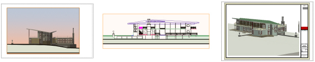
and Sectioning Elevation ViewsSection viewports are useful for creating images that show multiple design layers from a certain point of view.
For example, to show an exterior elevation of a building model, draw a section line outside of the model on one of the design layers and make all of the necessary layers visible in the section viewport. To show an interior view of the same model, do the same thing, but draw the section line through the model at the appropriate location.
See Creating Interior Elevation Viewports for an alternative method for creating as many as four interior elevation viewports with a single Comando.
Alternatively, if you already have a (non-sectioned) sheet layer viewport that shows multiple design layers in an elevation view, you can draw the section line through the viewport at the appropriate location.
A section-elevation marker can be linked to the section viewport; see Section-Elevation Marker Tool.


~~~~~~~~~~~~~~~~~~~~~~~~~
 Creating a Horizontal Section Viewport
Comando |
Path |
|---|---|
Create Horizontal Section Viewport |
• View • Context Menu (for clip cube) |
Horizontal section viewports can be customized in several ways to display the view needed. They can be placed on sheet layers, to include annotations, automatically coordinate sheet and drawing numbers, and display multiple viewports with different views and scales on a single sheet. They can be placed on design layers to provide detailed views and so they can be referenced into other files.
Within a horizontal section viewport, you can set extents, display and attributes settings for the viewport overall, and then create override settings for certain objects by class or individually (see Displaying Objects in Horizontal Section Viewports).
To create a horizontal section viewport:
1 Prepare to create the viewport as follows:
• To create a section view from a design layer, make the design layer active.
• To create a section view from an existing viewport, select a non-sectioned viewport object. The viewport object must be in Top, Bottom, Left, Right, Front, or Back view orientation.
• To create a section view from an existing clip cube object, use the Selection tool to highlight the face of the clip cube where the section will begin. (See Viewing a Model with the Clip Cube.)
2 Select the Comando.
The Create Horizontal Section Viewport dialog box opens. The available Parâmetros depend on whether you choose to place the section viewport on a sheet layer or design layer.
The scale of a design layer section viewport is the same as the layer where it is placed. The rendering mode of the current layer is also used to render the design layer section viewport.
► Clique para exibir/ocultar parâmetros.
A horizontal section viewport is created on the selected layer, and the drawing switches to that layer, displaying the new section viewport.
~~~~~~~~~~~~~~~~~~~~~~~~~
 Setting
Horizontal Section Viewport Cut Planes and Extents
Setting
Horizontal Section Viewport Cut Planes and ExtentsYou can control the cut plane and extents of a horizontal section viewport itself, and you can also create different settings for individual 3D and hybrid objects when viewed within the horizontal section viewport.
When the section viewport is created from a clip cube, the cut plane and extents are automatically set to match the clip cube.
To set the cut plane and extents:
Click Cut Plane and Extents from one of the following locations, and set the Parâmetros in the Cut Plane and Extents dialog box.
• The Create Horizontal Section Viewport dialog box
• The Object Info palette or Properties dialog box of a horizontal section viewport
• The Cut Plane and Display dialog box for one or more selected 3D and hybrid objects; see Displaying Individual 3D and Hybrid Objects in Horizontal Section Viewports
► Clique para exibir/ocultar parâmetros.
The cut plane and extents are set for the viewport, or for the selected objects, depending on how the dialog box was accessed.
~~~~~~~~~~~~~~~~~~~~~~~~~
 Displaying
Objects in Horizontal Section Viewports
Displaying
Objects in Horizontal Section ViewportsBy default, all objects seen in a horizontal section viewport take on the cut plane, display, and attributes settings of the viewport itself. However, this does not always result in the desired view. You can, instead, control the appearance of objects in the viewport by class, or by selecting and setting the Parâmetros for one or more 3D and hybrid objects in Edit in Place mode. These settings affect the objects’ appearance only within the horizontal section viewport, and do not change the settings in the model itself.
~~~~~~~~~~~~~~~~~~~~~~~~~
 Displaying
Objects by Class in Horizontal
Section Viewports
Displaying
Objects by Class in Horizontal
Section ViewportsThe display and pen attributes can be defined for objects by class to override the horizontal section viewport’s settings for objects above and/or below the cut plane. These by class settings apply only to the viewport view and do not affect the appearance of the model itself.
To control display and pen attributes by class:
1 Determine whether you need to set the display for objects below or above the cut plane, and then click the appropriate Object Display or Hidden Object Display from the Create Horizontal Section Viewport dialog box, or from the Object Info palette or Properties dialog box.
Hidden object display settings prescribe how objects that are obstructed by other objects display in the viewport.
The Object/Hidden Object Display by Class dialog box opens.
► Clique para exibir/ocultar parâmetros.
2 Select one or more classes to assign the same display and attributes settings, and do one of the following:
If there are many classes in the file, use the filter capability to located the needed classes.
• To set the attributes directly, click Edit, or double-click the selected classes.
• To import attributes from another viewport in the file, click Import.
• To set the objects in the class to retain the display settings from the design layer viewport in a sheet layer viewport, select Use embedded design layer viewport settings.
The settings are applied to the selected classes.
~~~~~~~~~~~~~~~~~~~~~~~~~
 Displaying
Individual 3D and Hybrid Objects in Horizontal Section
Viewports
Displaying
Individual 3D and Hybrid Objects in Horizontal Section
ViewportsCut plane, display, and attributes can be set for individual 3D and hybrid objects to override the horizontal section viewport’s settings and the object’s settings for display outside the viewport. This can be done only within the viewport’s Edit in Place mode.
To set the appearance of a hybrid object viewed in a horizontal section viewport:
1 Right-click on the horizontal section viewport and select Edit Section in Place from the context menu.
2 In Edit in Place mode, select one or more eligible 3D and hybrid objects to assign the same cut plane and display Parâmetros.
When objects are not displayed in the current viewport view, Modo de Seleção Raio X allows hidden objects to be visible and selected, while in Edit in Place mode.
3 Click Cut Plane and Display from the Object Info palette, and set the Parâmetros in the Cut Plane and Display dialog box.
► Clique para exibir/ocultar parâmetros.
~~~~~~~~~~~~~~~~~~~~~~~~~
 Object/Hidden Object Display and Pen
Attributes
Object/Hidden Object Display and Pen
AttributesEdit the display and pen attributes of objects in the viewport. This dialog box can be accessed from the Object/Hidden Object Display by Class dialog box to set the display for the objects in one or more classes, or from the Cut Plane and Display dialog box, to set the pen attributes for individual 3D and/or hybrid objects in the viewport.
► Clique para exibir/ocultar parâmetros.
~~~~~~~~~~~~~~~~~~~~~~~~~
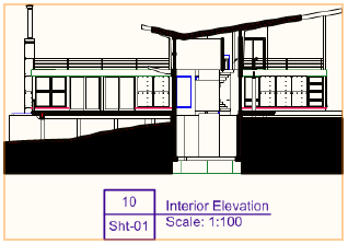
 Creating Interior Elevation Viewports
Comando |
Path |
|---|---|
Create Interior Elevation Viewport |
View |
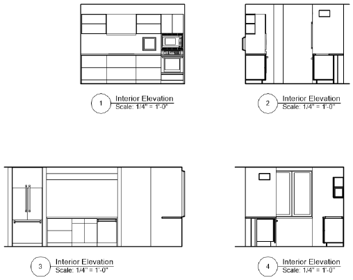
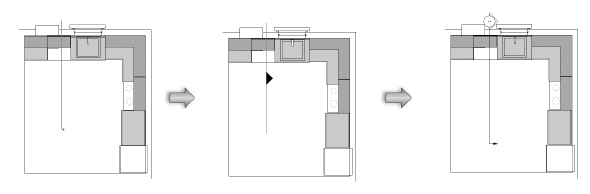
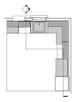
The Create Interior Elevation Viewport Comando creates as many as four interior elevation viewports of a room or area of a model at the same time. Interior elevation viewports are a kind of section viewport, but rather than creating a cross section of the area, the Comando creates section lines with extents defined by the walls that surround the interior-elevation marker. The drawing’s automatic coordination among the interior-elevation marker and the associated viewports is maintained as long as the viewports are kept on the same sheet layer or design layer on which they are originally created.
By default, the vertical extent of the section lines is determined by the bottom of the lowest wall and the top of the highest wall of all layers visible in a sheet layer viewport, or by the height of the active layer for a design layer viewport. By default the horizontal extent is determined by the nearest walls in the XY direction of each section line; if there is no wall in a direction, the extent will be determined by the bounding box of the nearest object. Section lines, which are not visible on the design layer, can be edited after creation by clicking Edit Section Lines from the Object Info palette or by double-clicking the interior-elevation marker.

To create interior elevation viewports:
1 Make sure the desired design layer is active, and set the drawing to Top/Plan view.
Once the viewports are created, the interior-elevation marker displays on the active design layer. The viewports are connected to this marker for ease of editing and automatic coordination.
2 Select the Comando.
3 Click once to place the interior-elevation marker in the drawing, and click again to set the rotation.
The Create Interior Elevation Viewports dialog box opens to set the viewport properties.
► Clique para exibir/ocultar parâmetros.
The interior elevation viewports are created on the layer specified.
The interior-elevation marker displays on the design layer that was active when you created the viewports. It is updated to reflect which viewports were created, and to display with the selected settings. Associated viewports are placed on the specified sheet layer or design layer; moving individual viewports to a different layer breaks the association with the interior-elevation marker and the other viewports, and the relocated interior elevation viewport is converted to a section viewport.
|
Clique aqui para uma dica em vídeo sobre este tópico (requer acesso a internet) |
 Editing
Interior Elevation Viewports
Editing
Interior Elevation ViewportsInterior elevation viewports are technically section viewports, and they can be edited using many of the same techniques described in Modifying Section Viewports and Section Lines.
Moving the marker with click-and-drag does not affect the placement of the section lines that define the viewports, but rotating the marker using the Rotate tool rotates all the section lines associated with the marker.
To edit the individual section lines that define the viewport, either double-click the associated interior-elevation marker or click Edit Section Lines from the marker’s Object Info palette to enter Object Editing Mode. Then edit the lines using the control points and the Selection tool and Reshape tool as described in Modifying Section Lines Graphically.
Cropping Existing Sheet Layer or Design Layer Viewports is possible for interior elevation viewports. If the section lines that define the viewport are edited after a viewport is cropped, you may need to remove or change the crop to get the desired result.
~~~~~~~~~~~~~~~~~~~~~~~~~
 Interior-Elevation
Markers
Interior-Elevation
MarkersTool |
Tool set |
|---|---|
Interior-Elevation Marker
|
Dims/Notes |
There are two kinds of interior-elevation markers in Vectorworks. The viewport-linked marker is placed when you create interior elevation viewports (see Creating Interior Elevation Viewports); it maintains coordination with the viewports for automatic updates. This kind of marker is placed on the active design layer and graphically indicates for which directions the viewports were created. Specify the graphic properties, such as the marker style, when you create the interior elevation viewports. To access the marker from any of the associated viewports, click Navigate to Interior Elevation from the viewport’s Object Info palette.
The simple interior-elevation marker (available with Vectorworks Fundamentals) looks identical on a drawing, but it is placed using the Interior-Elevation Marker tool and is simply a visual marker, not linked to a viewport.

To insert a simple interior-elevation marker:
1 Click the tool.
2 Click to place the object in the drawing, and click again to set the rotation.
The first time you use the tool in a file, a properties dialog box opens. Set the default properties. The properties can be edited from the Object Info palette.
Interior-elevation marker properties can be set before the marker is inserted in the drawing. If the marker is being placed by the Create Interior Elevation Viewports Comando (Vectorworks Architect required), click Interior Elevation Settings on the Create Interior Elevation Viewports dialog box to open the Interior Elevation Settings dialog box. If you are placing a simple marker using the Interior-Elevation Marker tool, click Preferences to open the object properties dialog box. These preferences serve as the new default for interior-elevation markers inserted in the drawing using that insertion method until the preferences are changed.
The Parâmetros can be edited for selected interior-elevation markers after placement, in the Object Info palette. The available Parâmetros are different, and displayed in a different order, for viewport-linked and simple interior-elevation markers.
The viewport-linked and simple interior elevations markers can be easily distinguished at the top of the Object Info palette. Markers that are linked to viewports are identified as the object type “Interior Elevation,” while the simple markers are identified as “Interior-Elevation Marker.”
► Clique para exibir/ocultar parâmetros.
~~~~~~~~~~~~~~~~~~~~~~~~~
 Creating Detail Viewports
Comando |
Path |
|---|---|
Create Detail Viewport |
View |
The Create Detail Viewport Comando creates a cropped sheet layer viewport that shows a detail view of any part of a drawing. A detail viewport can be created from a design layer, another sheet layer viewport, or a section viewport.
The crop object used to create the detail viewport becomes a callout object that is linked to the detail viewport for easy navigation between layers. If the detail callout object is moved or reshaped, the detail viewport updates accordingly. Additionally, the detail callout is automatically labeled with the drawing number and sheet number of the detail viewport. If the detail viewport is renumbered or moved to another layer, the callout label updates automatically.
In addition to the detail callout instance that is automatically created, a detail-callout marker can be linked to the detail viewport; see Detail Callouts and Detail-Callout Markers.
To create a detail viewport:
1 Create a crop object on a design layer (in Top/Plan view), on a sheet layer viewport (sectioned or not), or inside a viewport annotation group.
2 Select the crop object and then select the Comando.
The Create Detail Viewport dialog box opens. Different options are available, depending on where the crop object is located (design layer, viewport, or section viewport). Specify the desired Parâmetros.
► Clique para exibir/ocultar parâmetros.
The specified sheet layer is activated, and the detail viewport is placed in the center of the sheet.
Additionally, the original crop object is converted into a detail callout object. If the detail viewport is created from a design layer, the detail callout is created on the design layer. If the detail viewport is created from a viewport, the detail callout is created in the annotation space of that viewport. The callout includes the drawing number and sheet number of the detail viewport associated with it.


3 You can create additional instances of the callout on other design layers or in the annotations of other viewports, if needed. See Detail Callouts and Detail-Callout Markers. A detail-callout marker can also be linked to a detail viewport.
4 To delete a detail viewport and its associated callouts, delete the viewport.
|
Clique aqui para uma dica em vídeo sobre este tópico (requer acesso a internet) |
~~~~~~~~~~~~~~~~~~~~~~~~~
 Detail Callouts and Detail-Callout
Markers
Detail Callouts and Detail-Callout
MarkersDetail callouts and detail-callout markers look very similar on the drawing, but they are created differently.
A detail callout is automatically created when a detail viewport is created. The detail callout and the detail viewport are linked, as described in Creating Detail Viewports. Specify the graphic properties of the detail callout (such as marker style) when you create the detail viewport. To modify the detail callout, or to change the view in the detail viewport that is linked to the detail callout, see Editing Detail Callouts. To access a detail callout from its detail viewport, click Detail Callout Instances from the Object Info palette (see Detail Callout Instances).
A detail callout that has been pasted from a copy, duplicated, or mirrored from a detail callout that is associated with a detail viewport becomes an “unlinked” detail callout. It displays with black and yellow stripes. In the Object Info palette, Detail Viewport displays Not Linked.
A detail-callout marker is graphically similar to a detail callout, but it is not necessarily linked to a viewport. Use the Detail-Callout Marker tool from the Dims/Notes tool set to insert a marker. Click Preferences to specify the graphic properties of the object before you create it.
A detail-callout marker can be linked to a viewport. Depending on the type of viewport it is linked to, its drawing number and sheet number are synced to the selected viewport, similar to a detail callout. Detail-callout markers that are linked to a viewport display with a green link icon next to the marker symbol. The linked detail-callout marker can have different graphic properties from a detail callout that is also associated with a detail viewport.
Tool |
Tool set |
|---|---|
Detail-Callout Marker
|
Dims/Notes |
To create a detail-callout marker, either use the Detail-Callout Marker tool or create a polyline and then select the Create Objects from Shapes Comando (see Creating Objects from Shapes).
The following modes are available.

Mode |
Descrição |
|---|---|
Oval |
Creates an oval detail-callout marker using Box mode; see Creating Ovals |
Rectangle |
Creates a rectangular detail-callout marker using Corner to Corner mode; see Creating Rectangles |
Rounded Rectangle |
Creates a rounded rectangular detail-callout marker using Proportional or Symmetrical mode; see Creating Rounded Rectangles |
Proportional |
Click to draw a rounded rectangular detail-callout marker with proportional corners |
Symmetrical |
Click to draw a rounded rectangular detail-callout marker with symmetrical corners |
Fillet Radius |
Enter the corner radius for a symmetrical rounded rectangular detail-callout marker |
Polyline |
Creates a polyline detail-callout marker using the six polyline creation options |
Polyline creation options |
Select one of six types of control points for the vertices of the polyline; see Creating Polylines. The Fillet Radius value for Arc Vertex Polyline mode is independent of the Fillet Radius value for Symmetrical Rounded Rectangle mode. |
Preferences |
Sets the default Parâmetros for detail-callout markers |
To insert a detail-callout marker:
1 Click the tool and then click Preferences to set the default Parâmetros for detail-callout markers.
2 Click a drawing mode from the Tool bar, and do one of the following:
• For a detail-callout marker in the shape of an oval, rectangle, or rounded rectangle, click to begin the shape, and then click to complete the shape and create the detail-callout marker.
• For a polyline detail-callout marker, click to begin the polyline, and then click to set each polyline vertex. Click the start point (for a closed polyline) or simply double-click to complete the polyline and create the detail-callout marker.
After creation, edit detail-callout markers as follows:
• Use the Object Info palette to edit the graphic properties (such as the marker style).
• Use the Attributes palette to apply attributes (such as the fill or pen color).
• Use options on the Text menu to control the text appearance (such as the font or size), or assign a text style.
• Use the Selection tool to adjust the marker label, or to move the entire detail-callout marker.
• Use the Reshape tool to reshape the detail-callout marker.
There are two reshape modes for both oval and rounded rectangular detail-callout markers. To reshape an oval detail-callout marker, click Polyline or Oval mode from the Tool bar. To reshape a rounded rectangular detail-callout marker, click Polyline or Rounded Rectangle mode. (See Modos de Remodelagem 2D.)
• To link a detail-callout marker to a viewport, select the viewport from the Link To Viewport list on the Object Info palette.
Parâmetros display on the Object Info palette for selected detail callouts and detail-callout markers. Many of these Parâmetros also display on the Detail Callout Settings dialog box, which you can access to edit when you create a detail viewport. If there are multiple instances of a detail callout, all instances are updated.
► Clique para exibir/ocultar parâmetros.
~~~~~~~~~~~~~~~~~~~~~~~~~
 Detail
Callout Instances
Detail
Callout InstancesDetail callout instances associated with a detail viewport can be added to or deleted from design layers or viewport annotations. In addition, the Detail Callout Instances dialog box provides an easy way to navigate from a detail viewport to its associated detail callouts.
To edit detail callout instances or navigate to a detail callout:
1 Select the detail viewport whose detail callout you want to navigate to or edit.
2 Click Detail Callout Instances from the Object Info palette.
The Detail Callout Instances dialog box opens.
► Clique para exibir/ocultar parâmetros.
3 To add another instance of the detail callout to a different design layer or to the annotations for a different viewport, click on the column next to that design layer or viewport. Alternatively, to remove a detail callout instance from a layer or viewport, click the checked column (which removes the check mark).
Deleting all detail callout instances does not delete the detail viewport, and new instances can be created at any time. However, deleting a detail viewport deletes all detail callout instances.
4 The detail callout instances can also be used as a navigation tool to access a particular detail callout. Select the design layer or viewport where the detail callout instance is located, and click Activate to switch to the detail callout location; the detail callout is selected for any modifications.
To return from a detail callout instance to the associated detail viewport, click Navigate to Viewport from the Object Info palette of a selected detail callout.
~~~~~~~~~~~~~~~~~~~~~~~~~
Once it has been created, edit the viewport in the Object Info palette, or select Properties from the viewport’s context menu to open the Properties dialog box. There are additional methods of Modifying Viewports other than editing the Parâmetros.
A viewport is assigned to the None class by default when it is created; its class can be changed after creation. A viewport’s visibility is controlled by the class visibility settings (see Concept: Visibility of Drawing Elements).
When viewports are selected for editing, and if the Parâmetro settings of the selected viewports are different, Parâmetros display in an “indeterminate state.” Any values changed are changed for all the selected viewports.
Many Parâmetros can be edited from both the Properties dialog box and the Object Info palette for ease of access. The fields in the Object Info palette are named similarly (but not always identically) to those in the Properties dialog box. The Parâmetros are described in the sections listed, which explain how to create each kind of viewport. Only the Parâmetros that are different in the Object Info palette are listed here.
• Creating Sheet Layer Viewports
• Creating Design Layer Viewports
• Creating a Vertical Section Viewport
• Creating a Horizontal Section Viewport
• Creating Interior Elevation Viewports
► Clique para exibir/ocultar parâmetros.
~~~~~~~~~~~~~~~~~~~~~~~~~
To access additional sheet layer viewport Parâmetros, click Advanced Properties from the Object Info palette or Properties dialog box of a selected viewport. The Advanced Viewport Properties dialog box opens. These settings affect the viewport display only; they do not change the original design layer(s).
► Clique para exibir/ocultar parâmetros.

~~~~~~~~~~~~~~~~~~~~~~~~~
 Advanced
Design Layer Viewport Properties
Advanced
Design Layer Viewport PropertiesTo access additional design layer viewport Parâmetros, click Advanced Properties from the Object Info palette of a selected viewport. The Advanced Viewport Properties dialog box opens. These settings affect the viewport display only; they do not affect the original design layer(s).
► Clique para exibir/ocultar parâmetros.

~~~~~~~~~~~~~~~~~~~~~~~~~
 Advanced Section Viewport Properties
Advanced properties define the extents and attributes of the section viewport. Specify them when the viewport is created, or after the viewport has been created; edit the properties from either the Object Info palette or the Properties dialog box.
Finite sections are useful when you want to create interior elevations. For example, draw a section line across a particular room of a building, and set the layer visibility only for the room’s floor to create an interior elevation of only that room. For an even more precise interior elevation, use a clip cube to create the section viewport; the extents are automatically set according to the clip cube’s shape.
The X, Y position of perspective vertical section views is at the center of the section line. The Z position depends on the height range selection (finite or infinite).
To specify the advanced properties of a section viewport:
1 From the Create Section Viewport dialog box or Create Horizontal Section Viewport dialog box, click Advanced Section Properties.
Alternatively, select the viewport, and then from the Object Info palette or the Properties dialog box, click Advanced Properties.
The Advanced Section Properties/Advanced Horizontal Section Properties dialog box opens.
2 For vertical section viewports, click the Extents tab to specify either an infinite section view, or the length, height, and depth of a finite vertical section viewport.
Extents for horizontal section viewports are managed from the Cut Plane and Extents dialog box; see Setting Horizontal Section Viewport Cut Planes and Extents).
► Clique para exibir/ocultar parâmetros.
3 Click the Attributes tab to specify the appearance of objects on and beyond the section plane. Objects on the cut plane can maintain an individual profile, or can be divided into structural and non-structural groups to display them differently according to class settings.
Certain 3D objects can be designated as structural, allowing their appearance to merge with other structural objects on the section plane. Merged objects display as a single unit with one continuous fill. The following objects can be designated as structural by selecting Merge with Structural Objects in Sections from the Object Info palette.
• CSG solids (add/subtract/intersect/section) |
• Deforms (generic solid) |
• Extrudes |
• Multiple extrudes |
• Extrude along paths |
• Chain extrudes |
• Tapered extrudes |
• Cylinders (extrude) |
• Extruded rectangles (extrude) |
• Extruded polygons (mesh) |
• Meshes |
• Subdivisions |
• Solids (sphere/cone/hemisphere) |
• Sweeps |
• Stair structures (top face, bottom face, front face, inside/outside) |
• NURBS surfaces |
► Clique para exibir/ocultar parâmetros.
4 Click the Display tab to specify the section viewport display properties.
► Clique para exibir/ocultar parâmetros.
~~~~~~~~~~~~~~~~~~~~~~~~~