Comando |
Caminho |
|---|---|
Edit Viewport |
• Modify • Context menu |
There are various ways to modify viewports; their appearance can be completely different from the original design layers, for presentation purposes.
Modification |
Description |
|---|---|
Change the settings for the viewport in the Object Info palette |
|
Modify the viewport with various 2D and 3D tools and commands |
|
Add annotations and dimensions to the viewport |
|
Crop the viewport |
|
Edit one or more design layers in a live section or elevation |
|
Edit a design layer displayed in the viewport |
|
Edit or delete a linked Renderworks camera |
|
Change the properties of the viewport’s layers and classes |
Changing the Layer Properties of Sheet Layer or Design Layer Viewports and Changing the Class Properties of Sheet Layer or Design Layer Viewports |
Change the attributes of the objects in the viewport based on their attached record formats |
To modify a viewport:
Select the viewport and select the command. The Edit Viewport dialog box opens. The options available depend on whether the viewport is on a sheet layer or design layer (Vectorworks Design Series required).
► Clique para exibir/ocultar parâmetros.
~~~~~~~~~~~~~~~~~~~~~~~~~
A viewport can be edited like most 2D objects. For information on editing tools and commands, see Editing Geometry. 3D tools cannot be used on sheet layers. However, a 3D object can be copied from a design layer and pasted on a sheet layer. A design layer viewport (Vectorworks Design Series required) cannot be pasted on a sheet layer.
• Use the Cut, Copy, and Paste commands to copy or paste a viewport on its original sheet layer or another sheet or design layer. Use the Selection tool to drag a viewport to a new position (or edit the X- and Y-axis positions in the Object Info palette). Press the Delete key to delete a selected viewport.
• Use the Move and Rotate commands and the Rotate and Mirror tools to move, rotate, or mirror a viewport. The viewport can be split by the Split tool (in Line Split mode), and clipped with the Clip tool.
• Use the Scale Objects command to scale a sheet layer viewport. Any crop objects in the viewport are also scaled, as are annotations and dimensions. Viewport text, however, is not scaled unless Scale Text is selected in the Scale Objects dialog box.
• Use the Modify > Lock and Modify > Unlock commands to lock and unlock viewports.
• Use the Eyedropper tool to transfer attributes from one viewport to another; see Transferindo Atributos.
• Use 2D drawing tools on sheet layers to create title block borders, and so on.
• A sheet layer viewport can be copied and pasted into an image-editing application. The dpi setting of the sheet layer affects the resolution of the pasted image. Depending on the platform and the image-editing application, the resolution of the pasted image may still not be optimal; in this case, the File > Export Image File command offers control over the exported area, dimensions, resolution, and file type.
~~~~~~~~~~~~~~~~~~~~~~~~~
Command |
Path |
|---|---|
Edit Viewport |
• Modify • Context menu |
Use the Edit Annotation mode to add annotations and dimensions in viewports, and to edit those annotations and dimensions later.
To add annotations, including dimensions, to a viewport:
1 With the viewport’s sheet layer active, select the viewport by clicking on it with the Selection tool.
2 Select the command. The Edit Viewport dialog box opens (see Modificando Viewports for a description of the dialog box parameters).
3 Click Annotations to enter Edit Annotation mode.
Alternatively, right-click on a viewport and select Edit Annotations from the context menu.
A colored border around the drawing window indicates that you are in an editing mode. The Exit Viewport command becomes available from the Modify menu, and the Exit Viewport Annotation button is visible in the top right corner of the drawing window.
4 Use the various dimension tools from the Dims/Notes tool set to add dimensions to the viewport (see Cotas e Anotações). The dimension tools snap to the objects in the viewport as if you were dimensioning the design layer. The dimensions are automatically updated if the design layer object changes.
Annotations are 2D objects that are placed on the screen plane. Therefore, a 2D object in the viewport must be dimensioned in Top/Plan view. A 3D object can be dimensioned in any view, but you must align the face that is to be dimensioned with the screen plane to get an accurate measurement.
To view other objects on the sheet layer while in Edit Annotation mode, select Show other objects while in editing modes on the Display tab of the Vectorworks preferences (see Aba de Visualização).
Text, callouts, and other annotations, as well as 2D objects, can be added to the viewport. The Vectorworks Design Series products contain additional annotation objects.
The stacking order of selected annotations can be changed with the Modify > Send commands. To add graphical annotations to a viewport rendered with Hidden Line, use the Inner Boundary or Outer Boundary mode of the 2D Polygon tool (see Ferramenta de Polígono 2D).
Annotations are in viewport scale, not sheet layer scale.
5 Click Exit Viewport Annotation to exit Edit Annotation mode and return to the sheet layer.
~~~~~~~~~~~~~~~~~~~~~~~~~
Command |
Path |
|---|---|
Edit Viewport |
• Modify • Context menu |
To crop a viewport:
1 Select the viewport.
2 Select the command. The Edit Viewport dialog box opens (see Modificando Viewports for a description of the dialog box parameters).
3 Click Crop to enter Edit Crop mode.
Choose whether to display the viewport outside of the crop area. Select Display Viewport Outside Crop to view the rest of the viewport; select Gray Outside Crop to view the area outside of the crop in gray. These options make drawing and editing easier, since objects outside the crop can be snapped to.
To view other layer objects while in Edit Crop mode, select Show other objects while in editing modes on the Display tab of the Vectorworks preferences (see Aba de Visualização).
Alternatively, right-click on a viewport and select Edit Crop from the context menu.
A colored border around the drawing window indicates that you are in an editing mode. The Exit Viewport Crop command becomes available from the Modify menu, and the Exit Viewport Crop button is visible in the top right corner of the drawing window.
4 Create a 2D object such as a rectangle, circle, or polyline. The 2D object must define an area; for example, a 2D line cannot be used. Position the 2D object to delimit the new viewport display area. The fill of a viewport cropping object is always None; however, the pen style can be set from the Attributes palette while in Edit Crop mode.
Use the Flyover tool to adjust the view (see Sobrevôo).
The bounding box of the crop object is also the perspective clip rectangle, if the viewport is in Perspective projection. Reshaping the crop object changes the perspective clip rectangle as well.
5 Click Exit Viewport Crop to return to the sheet layer or design layer.
6 The cropped viewport displays; in the Object Info palette, the Crop status changes to Yes.
7 To change, replace, or delete the crop object, select the viewport and then select Modify > Edit Viewport to re-enter Edit Crop mode. Alternatively, right-click and select Edit from the context menu.
To change the visibility of the crop object, change the Crop Visible setting in the Object Info palette.
~~~~~~~~~~~~~~~~~~~~~~~~~
 Editing
Design Layers from a Section or Elevation View
Editing
Design Layers from a Section or Elevation ViewCommand |
Path |
|---|---|
Edit Viewport |
• Modify • Context menu |
The Edit In-Place mode edits design layers in a live section, or in a live elevation (Vectorworks Architect required). The visual context of the live section or elevation (its view orientation, projection, rendered appearance, and visibilities) matches its source viewport, for a seamless transition to editing.
|
Click here for a video tip about this topic (internet access required). |
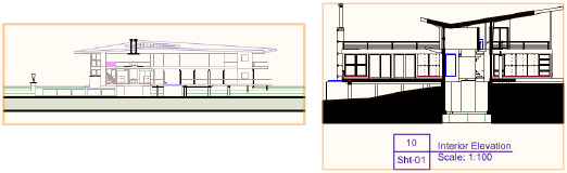
To edit a model in a live section or elevation:
1 Select a section viewport or interior elevation viewport.
2 Select the command. The Edit Viewport dialog box opens (see Modificando Viewports for a description of the dialog box parameters).
3 Click Section In-Place for a section viewport, or Elevation In-Place for an interior elevation viewport to enter Edit In-Place mode.
Alternatively, right-click on a viewport and select Edit Section In-Place, or Edit Elevation In-Place, from the context menu.
A colored border around the drawing window indicates that you are in an editing mode. The Return to Viewport command becomes available from the Modify menu, and the Return to Viewport button is visible in the top right corner of the drawing window.
4 The live section or elevation has the same layer and class visibilities as its source viewport. All objects on the viewport’s visible layers are available for editing in-place. Interactively edit the design layers. For example:
• Use the Flyover tool and View menu commands to change the view, showing surfaces that may not be accessible from the initial section or elevation view. See Sobrevôo and Utilizando Vistas Padrão.
All standard views are available except for Top/Plan view.
• Use the Reshape tool to change object dimensions. See Remodelando Objetos.
• Move an object to a wall on a different layer. See Movendo Objetos.
The movement of objects in walls is constrained horizontally. To remove this constraint for a selected wall, click the Reshape tool and click Reshape 3D Walls mode. See Reshaping Walls.
• Use the Mirror tool to mirror and duplicate objects on multiple layers. See Espelhando Objetos.
• Use the Align/Distribute command to align and distribute objects across layers. See Alinhando e Distribuindo Objetos.

5 To restore the original view, select Viewport View from the Current View/Standard Views list.
6 Click Return to Viewport to exit Edit In-Place mode. The viewport updates automatically.
Other viewports may become out of date.
~~~~~~~~~~~~~~~~~~~~~~~~~
Command |
Path |
|---|---|
Edit Viewport |
• Modify • Context menu |
To edit a design layer displayed in a viewport:
1 Select the viewport.
2 Select the command. The Edit Viewport dialog box opens (see Modificando Viewports for a description of the dialog box parameters).
3 Click Design Layer and select the design layer to edit from the list.
Alternatively, right-click on a viewport and select Edit Design Layer or Edit Referenced Design Layer from the context menu to activate the design layer of the right-clicked object (if the right-clicked object does not belong to a design layer, the Edit Viewport dialog box opens).
4 Choose how the design layer will display. Select Display using Viewport Attributes to change the file’s view settings and layer and class visibilities to match those of the viewport. If the Navigate Back to Viewport option is also selected, the file’s layer and class visibilities return to their original status when you return to the viewport; otherwise, the file’s attributes remain the same as the viewport’s.
A rendered viewport displays the original design layer with the viewport’s render mode; however, the design layer’s options for that render mode are used.
5 If the viewport has been cropped, select Add Reference Crop Object to display the crop on the design layer. Because the crop object is added to the design layer, it could become visible in other viewports that reference that area. The appearance of the crop object can be edited in the Attributes palette.
6 Select Navigate Back to Viewport to return to the viewport and to restore the file’s original layer and class visibilities when editing is complete.
7 If you are editing a section viewport, and Navigate Back to Viewport is selected, select Display with Clip Cube to display the design layer with a clip cube whose dimensions match the length, depth, and height ranges set for the viewport. Portions of the design layer outside the clip cube are not visible while editing.
8 After selecting the options, click OK to navigate to the selected design layer.
9 Edit the design layer objects as needed.
If you selected Navigate Back to Viewport, a colored border displays around the drawing window. The Return to Viewport command becomes available from the Modify menu, and the Return to Viewport button is visible in the top right corner of the drawing window.
10 If you selected Display with Clip Cube, switch to an isometric view to see the clip cube. Edit the clip cube to change the extents of the viewport. See Exibindo um Modelo no Recorte Cúbico for details.
11 Do one of the following when your edits are complete:
• Click Return to Viewport to return to the viewport. This saves changes to drawing objects, but it does not save clip cube edits.
• Press Shift+Esc to exit to the design layer instead of exiting to the viewport. Alternatively, right-click in the drawing area, and select Exit Viewport from the context menu.
• If a clip cube is displayed, right-click the cube face where the section was created; select Update Section Viewport (Vectorworks Design Series required) to save the clip cube edits. Then either click Return to Viewport, or select Exit Viewport from the context menu to exit editing mode.
• If a clip cube is displayed, right-click any vertical cube face other than the one where the section was created; select Create Section Viewport (Vectorworks Design Series required) to create a new section viewport with its section line located at that cube face.
~~~~~~~~~~~~~~~~~~~~~~~~~
Command |
Path |
|---|---|
Edit Viewport |
• Modify • Context menu |
You can edit a linked Renderworks camera, to change the associated sheet layer viewport’s view.
To edit a linked Renderworks camera:
1 Select the viewport.
2 Select the command. The Edit Viewport dialog box opens (see Modificando Viewports for a description of the dialog box parameters).
3 Click Camera to enter Edit Renderworks Camera mode.
Alternatively, right-click on a viewport and select Edit Camera from the context menu.
A colored border around the drawing window indicates that you are in an editing mode. The Exit Renderworks Camera command becomes available from the Modify menu, and the Return to Viewport button is visible in the top right corner of the drawing window.
4 The design layer that was active when the viewport was created is active, and the linked Renderworks camera object is selected. Edit the camera view as described in Ajustando a Visão de Câmera.
The camera can be deleted. The view and projection parameters are controlled by the viewport if the camera is deleted.
If no Renderworks camera is linked to the viewport, select a camera to be linked. Alternatively, the view can be manipulated with the standard view tools (such as the Flyover tool, zoom level, and View menu commands), changing the viewport view upon exit.
5 Click Return to Viewport to return to the viewport once the Renderworks camera has been edited or deleted. The viewport’s view, projection, and perspective distance are updated.
~~~~~~~~~~~~~~~~~~~~~~~~~
 Modifying Section Viewports
and Section Lines
Modifying Section Viewports
and Section LinesSection viewports can be modified, cropped, annotated, and updated, similarly to sheet layer viewports. See Modificando Viewports and Atualizando Viewports.
The appearance of a section viewport, including an interior elevation viewport, can be completely customized, from the items it displays to the attributes of those items. Copies of a section viewport on a sheet layer can look completely different. Changes to a section viewport’s appearance can be made by several methods; after changes are made, update the section viewport by clicking Update from the Object Info palette.
Modification |
Method |
Description |
|---|---|---|
Change the section view |
Click Advanced Properties from the Object Info palette of a selected section viewport, and modify the section view from the Extent tab |
|
Change the view attributes |
Click Advanced Properties from the Object Info palette of a selected section viewport, and modify the attributes of the view from the Attributes tab |
|
Change the view direction of the section line (not available for interior elevation viewports) |
Click Reverse Direction from the Object Info palette of a selected section viewport |
|
Change the cross section appearance for sectioned items (not available for interior elevation viewports) |
The cross section appearance is set by the Section Style class. Edit the class to change the appearance of sectioned items. If the Section Style class is made invisible, the cross sections are not displayed. |
|
Override the layer settings from the design layer |
Click Layers from the Object Info palette of a selected section viewport, and override the layer properties. Unlike a regular sheet layer viewport, the design layer stacking order in the section viewport cannot be changed. |
Changing the Layer Properties of Sheet Layer or Design Layer Viewports |
Override the class settings from the design layer |
Click Classes from the Object Info palette of a selected section viewport, and override the class properties of “by class” objects |
Changing the Class Properties of Sheet Layer or Design Layer Viewports |
Change the location of the section line |
Change the location of the section line with the Selection tool, and update the section viewport |
|
Create section viewports from unlinked section lines (not available for interior elevation viewports) |
Select the unlinked section lines and then select the Create Section Viewport command to create section viewports from the section lines |
Creating Vertical Section Viewports from Unlinked Section Lines |
Add additional section line instances to design layers or viewports (not available for interior elevation viewports) |
Click Section Line Instances from the Object Info palette of a selected section viewport, and specify the design layers or viewports where section line instances should display |
|
Change the section line length, position, or type |
Change the section line with the Selection tool or the Reshape tool, and update the section viewport |
|
Change the depth of a finite section |
The depth can be changed graphically or by modifying the Depth Range in the Advanced Properties of the section viewport |
Modifying Section Lines Graphically, or Advanced Section Viewport Properties |
~~~~~~~~~~~~~~~~~~~~~~~~~
 Modifying
Section Lines Graphically
Modifying
Section Lines GraphicallyIn addition to modifying section line parameters as described in Editing Section Lines and Section-Elevation Markers, the section line can be modified by changing its location, length, or shape.
To modify a section line:
1 Navigate to the section line by clicking Section Line Instances from the Object Info palette of a selected section viewport.
2 The section line is automatically selected for modification.
• Move the section line to a new location with the Selection tool.
• Shorten, lengthen, or rotate the line by dragging an end point with the Selection tool.
• Add vertices and change a straight section line to a broken section line with the Reshape tool.
• Reshape the section line with the Reshape tool.

3 A section view with a finite depth has a special control point on a dashed line. To adjust the depth, drag the control point with the Selection tool.
4 Return to the section viewport by clicking Activate Section Viewport from the Object Info palette. Click Update from the Object Info palette to reflect the section line changes in the section view.
~~~~~~~~~~~~~~~~~~~~~~~~~
 Editing
Detail Viewport Drawing Labels
Editing
Detail Viewport Drawing LabelsCommand |
Path |
|---|---|
Edit Viewport |
• Modify • Context menu |
After creation, the detail viewport drawing label can be edited, either to change its appearance, or to change the information that it displays. Edit the drawing label from within the detail viewport’s annotation space.
If Use Automatic Drawing Coordination is selected in document preferences, a change to the Drawing Number field for the detail viewport automatically changes the field for the viewport’s drawing label, and vice versa. Additionally, if Auto-coordinate is selected for the detail callout, a change to the Drawing Number field for the viewport automatically changes the field for the detail callout.
There are several ways to change the appearance of a detail viewport drawing label.
• Use the Attributes palette to change the label’s line color or thickness.
• Use the Object Info palette to change the object properties.
• Use the Text menu to change the attributes of the label text (or apply a text style to it).
• Use the Selection tool to adjust the label position.
To edit a detail viewport drawing label:
1 Select the detail viewport and then select the command. The Edit Viewport dialog box opens.
2 Click Annotations to enter Edit Annotation mode.
Alternatively, right-click on a viewport and select Edit Annotations from the context menu.
A colored border around the drawing window indicates that you are in an editing mode. The Exit Viewport command becomes available from the Modify menu, and the Exit Viewport Annotation button is visible in the top right corner of the drawing window.
3 Select the drawing label and edit it. The parameters in the Object Info palette are described in Criando Rótulos do Desenho.
4 Click Exit Viewport Annotation to exit Edit Annotation mode and return to the sheet layer.
~~~~~~~~~~~~~~~~~~~~~~~~~
 Editing
Detail Callouts
Editing
Detail CalloutsAfter creation, the detail callout can be edited, either to change the appearance of the callout itself, or to change the view in the detail viewport that is linked to the detail callout. The edit method depends on where the detail callout was created. If the callout object was created on a design layer, select the callout and edit it directly. If the callout object was created within a viewport’s annotation space, select the viewport and edit its annotations (see Editing a Detail Callout in a Viewport).
If Use Automatic Drawing Coordination is selected in document preferences, a change to the Drawing Number field for the detail viewport automatically changes the field for the viewport’s drawing label, and vice versa. Additionally, if Text Auto-Fill is selected for the detail callout, a change to the Drawing Number field for the viewport automatically changes the field for the detail callout.
There are several ways to change the appearance of a detail callout.
• Use the Attributes palette to change the callout object’s line color, thickness, or type.
• Use the Object Info palette to change the object properties (see Detail Callouts and Detail-Callout Markers).
• Use the Text menu to change the attributes of the marker text (or apply a text style to it).
• Use the Selection tool to adjust the marker position, or to move the entire callout.
You can also adjust the shape or location of the callout object, which will change the contents of the detail viewport associated with the callout. If there are multiple instances of the detail callout, all instances are updated.
• Use the Reshape tool to reshape the callout object.
Command |
Path |
|---|---|
Edit Viewport |
• Modify • Context menu |
If the callout was created from a viewport, the callout object cannot be edited directly because it is in the viewport’s annotation space.
To edit a detail callout in a viewport:
1 Select the original viewport and then select the command. The Edit Viewport dialog box opens.
2 Click Annotations to enter Edit Annotation mode.
Alternatively, right-click on a viewport and select Edit Annotations from the context menu.
A colored border around the drawing window indicates that you are in an editing mode. The Exit Viewport command becomes available from the Modify menu, and the Exit Viewport Annotation button is visible in the top right corner of the drawing window.
3 Select the detail callout and edit it. The parameters in the Object Info palette are described in Properties of Detail Callouts and Detail-Callout Markers.
4 Click Exit Viewport Annotation to exit Edit Annotation mode and return to the sheet layer.
~~~~~~~~~~~~~~~~~~~~~~~~~
By default, a viewport displays its portion of the drawing and the objects it contains as they appear in the design layer; however, viewport display is very flexible for the purposes of presentation.
You may wish to have several viewports displaying the same contents, but in different ways, with certain classes or layers hidden, grayed, or changed. This can be done by overriding the layer or class properties for a sheet layer or, for the Design Series, design layer viewport.
Design Series products also include the ability to control the attribute display of sheet layer viewport objects based on the data in the attached record formats. This viewport data visualization provides amazing flexibility for displaying objects in viewports based on attached data values or data ranges.
Class overrides and data visualization cannot be used for a viewport at the same time.
~~~~~~~~~~~~~~~~~~~~~~~~~
The viewport’s layer visibility, opacity, stacking order, and colors can be changed from the sheet layer or the design layer (Vectorworks Design Series required). Other viewports, as well as the design layer properties, are not affected. The viewport attributes can be tailored for presentation; several copies of the same viewport can appear completely different.
To change the viewport layer properties:
1 Select the viewport.
2 From the Object Info palette, click Layers.
The Viewport Layer Properties dialog box opens. Change layer visibilities and/or make layer attribute overrides for the selected viewport.

► Clique para exibir/ocultar parâmetros.
3 To override the layer properties (for viewport display), select one or more viewport layers and click Edit.
Alternatively, double-click a viewport layer to edit it.
The Edit Viewport Design Layers dialog box opens.
4 The same parameters apply when you create a design layer (see Definindo Propriedades da Camada de Projeto); for viewport layers, only the stacking order, transfer mode or opacity, and colors can be edited. These edits apply to the current viewport only, though they can be transferred to other viewports with the Eyedropper tool.
The viewport layer colors can be controlled separately from the design layer colors, for flexible presentation output. Click Colors to override the fill and pen colors for the selected viewport layer. To see the effects of the color override, Use Layer Colors must be selected in the Viewport Layer Properties dialog box for the selected viewport. This is similar to the way that Use Layer Colors must be selected in document preferences to see the layer color settings for a design layer, as described in Setting the Design Layer Color.
5 Click OK to return to the Viewport Layer Properties dialog box.
Click Preview to evaluate the results of the property changes.
6 Click OK to return to the sheet layer or design layer.
~~~~~~~~~~~~~~~~~~~~~~~~~
The class visibilities and attributes of a selected viewport can be changed from the sheet layer or the design layer. This does not change the class properties or the class visibility for the original design layers or for other viewports. The viewport attributes can be tailored for presentation; several copies of the same viewport can appear completely different.
Class overrides and data visualization cannot be used for a viewport at the same time.
To override viewport class properties:
1 Select the viewport.
2 From the Object Info palette, click Classes.
The Viewport Class Properties dialog box opens. The dialog box functionality is slightly different for referenced (Vectorworks Design Series required) and non-referenced (internal) viewports. Change class visibilities and/or make class attribute overrides for the selected viewport.

► Clique para exibir/ocultar parâmetros.
~~~~~~~~~~~~~~~~~~~~~~~~~
 Viewport Data Visualization
Viewport data visualization allows you to control the attributes of objects in a sheet layer viewport according to the data present in their attached record formats. This method allows for flexible viewport display options by value or by ranges of values. Using the record data attached to objects allows you to visualize the object data in the viewports according to function, object type, or any other attached record parameter. For example, you can view the space objects in a viewport according to occupancy, usage, floor area value range, or any other record or parameter property. One data set can be presented in a variety of ways.
If more than one record format is applied to space objects in the drawing, data visualization may yield unexpected results. Either remove the additional record formats or resolve conflicting information before completing the data visualization operation.
The visualization is an effect applied to the viewport; no drawing objects are affected. Viewport data visualization requires wireframe rendering mode.
Data visualization settings can be transferred from one viewport to another with the Eyedropper tool; see Transferindo Atributos.
Class overrides and data visualization cannot be used for a viewport at the same time.
To change the appearance of viewport objects based on attached record data:
1 Select the sheet layer viewport.
2 From the Object Info palette, click Data Visualization.
The Viewport Data Visualization dialog box opens.
► Clique para exibir/ocultar parâmetros.
3 Select the record format and one of its record fields, and then choose whether to apply the visualization effect by numerical range (Attribute Ranges) or by value (Attribute Values). Determine whether to include groups and symbols among the objects to be considered.
The visualization effect applies to the records applied to symbol definitions and group containers, and not to records attached to objects within the symbol definition or group.
4 If setting attributes by range, click Add or Edit to specify the range values and attributes.
The Edit Attribute Range dialog box opens. Set the range limits and attributes.
► Clique para exibir/ocultar parâmetros.
5 If setting attributes by value, the values associated with the selected record field are listed, set to default attributes. Select a value and click Edit to specify the value’s attributes.
The Edit Attribute Value dialog box opens. Set the value attributes.
► Clique para exibir/ocultar parâmetros.
6 Several rows in the Options list can be selected at one time, changing any of the attributes of the selected row. When the attributes of the ranges or values have been set, save the settings as a set for reuse by clicking Save, if desired.
7 To enable the visualization effect for the selected viewport, select Enable Data Visualization for This Viewport. Individual rows in the Options list can also be enabled or disabled by clicking in the Apply column.
If you have saved settings for viewport data visualization, you can rename or delete these saved settings when needed.
To manage saved settings for viewport data visualization:
1 From the Object Info palette of a selected sheet layer viewport, click Data Visualization.
The Viewport Data Visualization dialog box opens.
2 Click Manage.
The Manage Saved Sets dialog box opens. Select the set to change.
► Clique para exibir/ocultar parâmetros.
~~~~~~~~~~~~~~~~~~~~~~~~~
The status of a viewport or section line is indicated visually.
Viewport Status |
Description |
|---|---|
Normal |
A normal, up-to-date viewport displays with orange highlighting when selected
|
Out of date |
When the objects in a viewport have changed since the viewport was created or last updated, the viewport becomes out of date. An out-of-date viewport is indicated by red text on the Update button on the viewport’s Object Info palette. Optionally, an out-of-date viewport also displays with a red and white striped border around the viewport (see Aba Visualização).
|
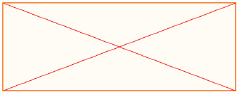
Empty |
A viewport displays as a red “X” when the associated design layer contains no objects or the objects are hidden, or when the associated design layer is set to “invisible”
|
Unlinked (section line) (Design Series required) |
An unlinked section line (disconnected from its associated section viewport, possibly because the section line was pasted from a copy, duplicated, or mirrored) displays as a black and yellow line, and “Not Linked” is displayed in the Object Info palette
|
~~~~~~~~~~~~~~~~~~~~~~~~~
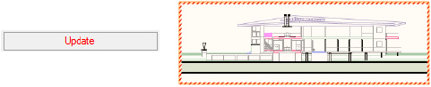
Changes that affect the appearance of a viewport are automatically updated for a wireframe viewport. However, if changes require the viewport to be rendered again, the viewport will be displayed as an out-of-date viewport.
If a sheet layer with an out-of-date viewport is printed, a message prompts you to either print the viewport as an out-of-date viewport or update the viewport on the sheet layer before printing.
Rendered viewport updates occur in the background for Renderworks render modes; you can continue working in the file while the viewports are updating. See Background Rendering.
Command |
Path |
|---|---|
Update Selected Viewports |
• View • Context menu |
To update selected viewports:
1 Select the viewports.
2 From the Object Info palette, click Update. Alternatively, select the command, or right-click on the viewport and select Update from the context menu.
Command |
Path |
|---|---|
Update All Viewports |
View |
To update all the viewports in the file:
Select the command.
All viewports on all sheet layers are updated.
Command |
Path |
|---|---|
Cancel All Viewport Updates |
View |
To cancel the updates of all viewports, including those queued to update for background rendering:
Select the command.
The updates are canceled.
~~~~~~~~~~~~~~~~~~~~~~~~~
In the Vectorworks Fundamentals workspace, the cutting section commands define a section line through a 3D model, placing the cut section on a new layer and leaving the original model intact.
Creating section viewports (Vectorworks Design Series required) may be preferable to creating cutting sections. However, the Cut 2D Section command and Cut 3D Section command can be added to Design Series workspaces if desired.
The Cut 2D Section command creates a cross-section, or 2D contour, on the cutting plane. The contour is created by the intersection of the model with an infinite plane passing though the section line. Only the elements that actually intersect the section line are shown.
The Cut 3D Section command creates a section with all the 3D geometry that remains on the indicated side of the infinite plane passing through the section line. The elements that intersect the section line, as well as the 3D geometry that exists beyond the line, are shown.
Place a 2D section, along with a bold line, on top of a 3D section, to show the cutting plane with the section behind it.
~~~~~~~~~~~~~~~~~~~~~~~~~
Command |
Path |
|---|---|
Cut 3D Section |
Model |
From the Vectorworks Fundamentals workspace, the Cut 3D Section command cuts a 3D section, or slice, through a 3D model while leaving the model intact. The slice is placed on a new design layer.
To cut a 3D section from a 3D model:
1 Select the 3D model to section.
2 Select the command (Fundamentals workspace only).
3 Click to set the start of the section. Draw a line across the object to define the section, and then click to set the end of the section.
When cutting a section while the drawing is in Top/Plan view, the cutting plane (and the cut edge of the object) is perpendicular to the active layer plane.
When cutting a section while in a 3D view, the cutting plane is perpendicular to the working plane.
4 Click on one side of the line to indicate the portion of the model to keep.
The Vectorworks program automatically creates a new design layer and places the cut 3D section on it. The original layer remains intact.

~~~~~~~~~~~~~~~~~~~~~~~~~
Command |
Path |
|---|---|
Cut 2D Section |
Model |
From the Vectorworks Fundamentals workspace, the Cut 2D Section command (Vectorworks Fundamentals workspace only) cuts a 2D section, or a slice, from a 3D model without affecting the model. The slice is then placed on a new design layer. For example, to show the profile or a 2D cutaway section of an object in a mechanical 3D drawing, use this command to create the cutaway section in 2D quickly and easily, without affecting the original object.
To cut a 2D section from a 3D model:
1 Select the 3D model to section.
2 Select the command (Fundamentals workspace only).
3 Click to set the start of the section. Draw a line across the object to define the section, and then click to set the end of the section.
When cutting a section while the drawing is in Top/Plan view, the cutting plane (and the cut edge of the object) is perpendicular to the active layer plane.
When cutting a section while in a 3D view, the cutting plane is perpendicular to the working plane.
4 Click on one side of the line to indicate the portion of the model to keep.
The Vectorworks program automatically creates a new design layer and places the cut 2D section on it. The original layer remains intact.
Command |
Path |
|---|---|
Create Layer Link |
View |
Layers are independent of each other. Each design layer has its own scale, view, and render status. In the Vectorworks Fundamentals product, however, a layer link can be created that combines the geometry of several design layers, including referenced layers, onto a single design layer. The linked objects on this design layer display in the same view and scale, and share the same render status. This can then be used to give an accurate depiction of how objects in each layer work together. For example, the various floors of a building can be drawn on separate layers and then linked together into a new layer to form an entire building.
In the Vectorworks Fundamentals product, consider using viewports instead of layer links, as they provide a better and easier way to present drawings.
In the Vectorworks Design Series products, layer links have been replaced by design layer viewports. For backward compatibility, the Create Layer Link command can still be added to any of the Vectorworks Design Series workspaces, and existing layer links can still be viewed and edited. For information on design layer viewports, see Creating Design Layer Viewports.
The layer link is created on a new design layer that contains links to the existing design layers of the drawing. 3D objects on selected layers are automatically linked; 2D planar or screen objects can be displayed in the layer link. Once the layer link is created, updates to the design layers are automatically reflected on the linked layer when a screen redraw occurs. However, this updating occurs only in one direction; any new objects or details added to the linked layer will not appear in any other layers. Linked objects cannot be edited on the linked layer; they must be edited on their source layer.
To create a layer link:
1 Create a new layer, and then make it the active layer.
This layer shows objects on all linked layers and any changes made to them.
2 Select the command (Fundamentals workspace only).
The Create Layer Link dialog box opens; the layer being linked to (the currently active layer) is not listed.
► Clique para exibir/ocultar parâmetros.
3 Select the design layers to be linked from the list of existing layers.
Linked layers are locked objects. To unlock a linked layer, select Modify > Unlock. Double-click an item in the layer link to return to its source layer and edit it.
To project 2D planar or screen objects after a layer link has been created, select and then unlock the layer link object. Select the options from the Object Info palette.
~~~~~~~~~~~~~~~~~~~~~~~~~
Layer link objects can be cropped in a similar manner to viewports (see Cropping Existing Sheet Layer or Design Layer Viewports), although the area outside of the crop cannot be displayed as it can for a sheet layer or design viewport. When cropped, only a portion of the layer link displays; increase the scale of the layer to create a detailed view. Layer links with workgroup-referenced layers can also be cropped.
To crop a layer link:
1 Select an existing layer link.
2 Unlock the layer link by selecting Modify > Unlock.
3 Click Edit Crop from the Object Info palette to enter the Layer Link Crop mode.
Alternatively, right-click on a layer link and select Edit Crop from the context menu.
A colored border around the drawing window indicates that you are in an editing mode. The Exit Crop command becomes available from the Modify menu, and the Exit Layer Link Crop button displays in the top right corner of the drawing window.
4 Create a 2D object such as a rectangle, circle, or polyline. The 2D object must define an area; a 2D line, for example, cannot be used. Position the 2D object to delimit the new crop display area. The fill of a cropping object is always None; however, the pen style can be set from the Attributes palette while in Edit Crop mode. Set the pen style to None (or the crop object class to invisible) to make the crop object invisible.
Use the Flyover tool to adjust the view (see Sobrevôo).
5 Click Exit Layer Link Crop, or select Modify > Exit Crop to return to the drawing.
The cropped layer link is displayed. In the Object Info palette, the crop status has changed to Yes.
By increasing the scale of the layer with the layer link, and making other layers visible, a floor plan can be displayed (original design layer) along with a detailed view of the floor plan (zoomed in, cropped layer link).
To change, replace, or delete the layer link crop, select the cropped layer link and then select Edit Crop from the Object Info palette to re-enter crop mode. Click Exit Layer Link Crop, or select Modify > Exit Crop to return to the drawing.
The entire layer link is displayed if a viewport of a cropped layer link is created.
~~~~~~~~~~~~~~~~~~~~~~~~~
 Converting Layer Links
In the Vectorworks Design Series products, layer links have been replaced by design layer viewports. Because users of the Vectorworks Fundamentals product cannot create design layer viewports, and users of the Vectorworks Design Series products cannot create layer links, it occasionally may be necessary to convert a layer link into a viewport, or to convert a design layer viewport into a layer link.
• To convert a layer link into a design layer viewport, first unlock the layer link. Then, right-click on the layer link, and select Convert to Viewport from the context menu.
• To convert a design layer viewport into a layer link, select the viewport and then select Modify > Decompose. The Object Info palette changes to indicate that the object is now a group. Select Modify > Ungroup to create a layer link.


 To
use the same class definition both in the current file and
in the viewport, click the
To
use the same class definition both in the current file and
in the viewport, click the