Viewport objects allow you to create views from several directions, complete with details, annotations, dimensions, and title blocks. Viewports can show other parts of the active document, or even portions of other documents.
Viewports can display entire, as well as cropped, views of a drawing, with specified layer and class visibility settings, projection, render mode, and orientation parameters. If the drawing changes, you can easily update the viewports to reflect the changes.
There are several different types of viewports, depending on whether you have the Vectorworks Fundamentals product or one or more Vectorworks Design Series products.
• Sheet layer viewports
In both the Vectorworks Fundamentals and Vectorworks Design Series products, you can create one or more viewports on a sheet layer, and each viewport can show one or more design layers from this document. Sheet layer viewports, often created for presentation purposes, are created on special layers called sheet layers. Sheet layers retain their own print settings, including print area, resolution, and printer setup parameters. For more information on sheet layers, see “Layers” on page 157.
When Renderworks is installed, a sheet layer viewport can be linked to a Renderworks camera.
• Design layer viewports (Vectorworks Design Series required)
Vectorworks Design Series products allow you to create one or more viewports on a design layer, and the design layers shown in the viewports can be either from this document, or referenced from another document. Like a sheet layer viewport, a design layer viewport can display design layers from the current file in a full or cropped view; unlike a sheet layer viewport, it can include one or more design layers that are referenced from another file.
• Section viewports (Vectorworks Design Series required)
A section viewport creates a cross section view of a model, but leaves the model intact. A section viewport can be created from a design layer or another non-sectioned viewport; it can be placed on a design layer or sheet layer.
• Detail viewports (Vectorworks Design Series required)
A detail viewport is a cropped sheet layer viewport that shows a detail view of any part of a drawing. A detail viewport can be created from a design layer, another sheet layer viewport, or a section viewport. The crop object used to create the detail viewport becomes a callout object that is linked to the detail viewport for easy navigation between layers.
The Viewports tab of the Organization dialog box differentiates among the various types of viewports.
Click here for a video tip about this topic (Internet access required).
~~~~~~~~~~~~~~~~~~~~~~~~~
To create a viewport from a design layer:
1. Select View > Create Viewport.
2. The Create Viewport dialog box opens. The viewport parameters are initially set to be the same as those of the design layer that is currently active, but they can be changed here. After the viewport has been created, additional parameters become available; see “Viewport Properties” on page 1632.
For Vectorworks Design Series products, the Create Viewport dialog box has additional functionality for creating design layer viewports; see “Creating a Design Layer Viewport from an Internal Design Layer” on page 1617.
Click to show/hide the parameters.
3. Enter the desired parameters and click OK.
4. If a sheet layer does not already exist in the file, the New Sheet Layer dialog box opens automatically to create one. Click OK.
The viewport is created on the designated sheet layer, and the sheet layer becomes active.
~~~~~~~~~~~~~~~~~~~~~~~~~
To create a cropped viewport either from a design layer or from an existing uncropped viewport on a sheet layer:
1. Make active the existing design layer or sheet layer that will display in the viewport.
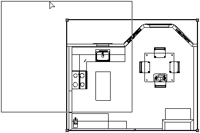
2. Create a 2D object such as a rectangle, circle, or polyline. The 2D object must define an area; for example, a 2D line cannot be used. Crop objects are automatically placed in the screen plane (see “Planar Modes of 2D Objects: Screen Plane and Layer Plane” on page 148). Position the 2D object on the design layer or existing uncropped viewport to delimit the area to be included in the new viewport. The fill of a viewport cropping object is always None; however, the pen style can be set from the Attributes palette.

3. If the cropped viewport is being created from a design layer, select the 2D object. If the cropped viewport is being created from a sheet layer, select both the 2D object and the uncropped viewport.
4. Select View > Create Viewport.
5. An alert dialog box asks whether the object should be used as the viewport’s crop. Select Yes (click Always do the selected action to always use a selected 2D object as a crop object when creating viewports).
6. The Create Viewport dialog box opens. Enter a viewport name and drawing title, and select the sheet layer to place it on. The remaining viewport parameters are initially set to be the same as the design layer properties (for design layers) or selected viewport (for sheet layers). Change the parameters as needed.
7. Click OK.
The viewport, cropped by the selected 2D object, is created on the specified sheet layer.
8. By default, the crop object is not visible. To change the visibility of the crop object, select the viewport and select the Crop Visible setting in the Object Info palette.

~~~~~~~~~~~~~~~~~~~~~~~~~
 Creating
Multiple Viewports Simultaneously
Creating
Multiple Viewports SimultaneouslyThe Create Multiple Viewports command generates 2D drawings from a 3D model and creates up to seven sheet layer viewports configured with several orthographic views and one isometric view of the model.
If you run the command from a sheet layer, the viewports are added to that sheet layer. If you run the command from a design layer, the viewports are added to a new sheet layer that is created automatically.
To create multiple viewports simultaneously:
1. Select View > Create Multiple Viewports.
The Create Multiple Viewports dialog box opens.
2. Specify the desired viewport scale, views, and angle projection method, and then click OK.
Click to show/hide the parameters.
Viewports are created at the designated layer scale, using the current layer and class visibility and print area settings, with the rendered style set to hidden line rendering. Viewports are aligned horizontally and vertically, separated by a fixed distance, and centered on the sheet layer.
3. Optionally, configure the viewports’ layer and class settings (Active, Show, or Gray Others only), annotate the viewport, or modify the rendering style or other viewport parameters.
For more information, see “Setting Class and Design Layer Visibility for Viewports and Saved Views” on page 192, “Creating Annotations for Sheet Layer Viewports” on page 1649, and “Viewport Properties” on page 1632.
~~~~~~~~~~~~~~~~~~~~~~~~~
 Creating
Design Layer Viewports
Creating
Design Layer ViewportsA sheet layer viewport displays a full or cropped view of one or more design layers, which you can change as needed and not affect the original drawing. For example, change the viewport’s layer and class visibilities, use a different render mode, or add annotations and dimensions. (See “Creating Sheet Layer Viewports” on page 1612.)
Design layer viewports provide different functionality, for more flexibility. Like a sheet layer viewport, a design layer viewport can display design layers from the current file in a full or cropped view; unlike a sheet layer viewport, it can include one or more design layers that are referenced from another file.
Like a sheet layer viewport, in a design layer viewport you can control layer and class visibility, and create layer and class overrides. However, because it is an object on a design layer, a design layer viewport has the same view, scale, and render mode as everything else on the layer. You can use 2D and 3D drawing tools to add objects to the design layer, but you cannot add annotations to a design layer viewport.
Design layer viewports replace the layer link functionality present in the Vectorworks Fundamentals product. Current layer links can be easily converted to a design layer viewport with the Modify > Convert > Convert to Viewport command. (See “Converting Layer Links” on page 1853.)
The search criteria used in worksheets and in the Script Editor allow you to filter out items from design layer viewports, to prevent unwanted duplicates in schedules.
~~~~~~~~~~~~~~~~~~~~~~~~~
 Creating
a Design Layer Viewport from an Internal Design Layer
Creating
a Design Layer Viewport from an Internal Design LayerTo create a design layer viewport that displays a design layer in the same file:
1. Select View > Create Viewport. Alternatively, from either the Organization dialog box or the Navigation palette, select the Viewports tab, and click New.
2. The Create Viewport dialog box opens. The scale, view, and render mode of the viewport are determined by the design layer on which it is placed; they cannot be changed here. Set the other viewport parameters as desired. After the viewport has been created, additional parameters become available; see “Editing a Design Layer Displayed in a Viewport” on page 1645.
Click to show/hide the parameters.
3. Click OK.
The viewport is created on the designated design layer, and the design layer becomes active. The viewport can be cropped, as described in “Cropping Sheet Layer or Design Layer Viewports” on page 1648.
~~~~~~~~~~~~~~~~~~~~~~~~~
 Creating
a Design Layer Viewport by Cropping
Creating
a Design Layer Viewport by CroppingThe viewport and the design layer that displays in it must both be in the same file.
To create a design layer viewport by cropping:
1. Access the design layer that will display in the viewport.
2. Create a 2D object such as a rectangle, circle, or polyline. The 2D object must define an area; for example, a 2D line cannot be used. Crop objects are automatically placed in the screen plane (see “Planar Modes of 2D Objects: Screen Plane and Layer Plane” on page 148). Position the 2D object on the design layer to delimit the area to be included in the new viewport. The fill of a viewport crop object is always None; however, the pen style can be set from the Attributes palette.
3. Select the 2D crop object, and then select View > Create Viewport.
4. An alert dialog box asks whether the object should be used as the viewport’s crop. Select Yes (also select Always do the selected action to always use a selected 2D object as a crop object when creating viewports).
5. The Create Viewport dialog box opens. Select the design layer on which to create the viewport. The Source must be the current document. Specify the design layers and classes to display in the viewport. (See “Changing the Layer Properties of Sheet Layer or Design Layer Viewports” on page 1655 and “Changing the Class Properties of Sheet Layer or Design Layer Viewports” on page 1657.)
6. Click OK.
The viewport, cropped by the selected 2D object, is created on the specified design layer.
7. By default, the crop object is not visible. To change the visibility of the crop object, select the viewport and select the Crop Visible setting in the Object Info palette.

~~~~~~~~~~~~~~~~~~~~~~~~~
 Creating
a Referenced Design Layer Viewport
Creating
a Referenced Design Layer ViewportReferencing allows you to use information from other Vectorworks files in your file, including design layers, classes, and resources (such as hatches, worksheets, or symbols). There are two ways to reference design layers that are in other Vectorworks files:
• The default method in the Vectorworks Design Series products is to create a design layer viewport and then reference the desired design layers from the master file into the viewport, as described here. One advantage to this method is that all of the layers, classes, and resources from the master file are not automatically imported into the target file.
• In the Vectorworks Fundamentals product, design layers are imported into the target file when they are referenced. For backward compatibility, the Vectorworks Design Series products support this method. See “Adicionando e Editando Referências de Importação de Camada” on page 205.
A reference for a design layer viewport can be created when the viewport is created, or it can be created ahead of time from the References tab of the Organization dialog box.
To create a design layer viewport that references a design layer in another file:
1. If the current file uses layer import referencing, switch to design layer viewport referencing. (From the References tab of the Organization dialog box, click Settings, and click the Design layer viewports option on the Reference Settings dialog box. Any existing referenced layers are automatically converted into referenced design layer viewports.)
2. Select View > Create Viewport. Alternatively, from either the Organization dialog box or the Navigation palette, select the Viewports tab, and click New.
3. The Create Viewport dialog box opens. Enter a Viewport Name and Drawing Title, and then select the design layer on which to create the viewport.
4. Click Select Source to open the Select Viewport Source dialog box, and enter information about the referenced document.
Click to show/hide the parameters.
5. Click OK in the Select Viewport Source dialog box to return to the Create Viewport dialog box.
6. Specify the design layers and classes to display in the viewport (see “Changing the Layer Properties of Sheet Layer or Design Layer Viewports” on page 1655 and “Changing the Class Properties of Sheet Layer or Design Layer Viewports” on page 1657).
7. Click OK.
The viewport is created on the designated design layer, and the design layer becomes active. The viewport can be cropped, as described in “Cropping Sheet Layer or Design Layer Viewports” on page 1648.
The master file displays on the References tab of the Organization dialog box; for details about how to edit, update, or delete references, see “Workgroups and Referencing” on page 203.
~~~~~~~~~~~~~~~~~~~~~~~~~
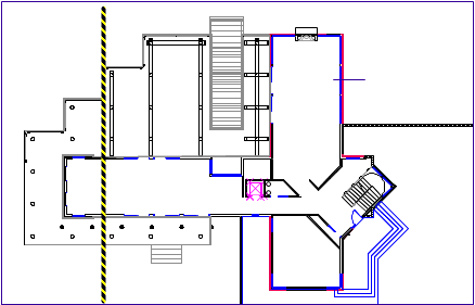
 Creating Section Viewports
A section viewport creates a cross section view of a model, but leaves the model intact. The section viewport can display a 2D cross section view of only the objects that intersect the section line, or, additionally, the 3D geometry that remains on the indicated side of an infinite plane passing through the section line.
Create a live section view from one or more design layers, from a clip cube on a design layer, or from a viewport on a sheet layer or design layer. By creating several section viewports, models can be analyzed and presented effectively. The section views can be updated as the model changes, and their attributes and appearance can be easily changed.
A section viewport can be created on either a sheet layer or a design layer; the functionality and purpose of the two types of section viewports are different.
Section viewports on sheet layers can include annotations and automatic drawing coordination of the sheet and drawing numbers; also, if there are multiple viewports on a sheet layer, each can a have different view and scale. These types of sections are always Top/Plan since they are on sheet layers, and are created for construction drawings. To get a 3D “look,” switch to Perspective Projection.
Section viewports on design layers are useful when, for example, a detail section is needed in a Front rendered view. A design layer section viewport allows comparison between a section and an elevation view. In a team environment, the design layer section viewport can be referenced in other files.
For sheet layer section viewports, to automatically coordinate the sheet numbers and drawing numbers among the sheet borders, drawing labels, and section markers in a file, select Use Automatic Drawing Coordination in the Display tab of the Document Preferences. This feature keeps references up to date, even when drawings are edited or moved to a different layer.
~~~~~~~~~~~~~~~~~~~~~~~~~
 Creating
a Section Viewport on a Sheet Layer
Creating
a Section Viewport on a Sheet LayerWhen you create a section viewport, you can place it on either a sheet layer or design layer. Section viewports on sheet layers can have annotations and automatic drawing coordination of the sheet and drawing numbers; also, if there are multiple viewports on a sheet layer, each can a have different view and scale.
If you need to draw a detailed section, or to reference the section viewport into other files, create the viewport on a design layer instead. (See “Creating a Section Viewport on a Design Layer” on page 1624.)
Create a section view from a design layer, from a clip cube, or from a viewport on a sheet layer. A section viewport that was created from a design layer or clip cube can be updated when changes are made to the design layer. However, a section viewport that was created from a viewport does not maintain a connection to the viewport that created it. It updates when the design layers that are visible in the source viewport change.
To create a section viewport on a sheet layer:
1. Prepare to create the viewport as follows:
• To create a section view from an active design layer, set the layer to Top/Plan view by selecting View > Standard Views > Top/Plan.
• To create a section view from an existing viewport, select a non-sectioned viewport object. The viewport object must be in Top, Bottom, Left, Right, Front, or Back view orientation.
• To create a section view from an existing clip cube object, use the Selection tool to highlight the vertical face of the clip cube where the section will begin. (See “Viewing a Model with the Clip Cube” on page 1151.) Right-click (Windows) or Ctrl-click (Mac) to open the context menu.
2. Select View > Create Section Viewport (for a design layer or viewport), or select Create Section Viewport from the context menu (for a clip cube).
3. Draw the section line to create the cutting plane on the design layer or viewport. For a clip cube, skip to step 4; the section line is created automatically from the clip cube face that was used to create the section viewport.
Click in the drawing and drag the mouse to begin drawing the marker line. Click to mark the end of the line, and then click to indicate the side of the line to look toward (keep), which is indicated by a black arrow. Double-click to end the line.
To create a broken section line, click in the drawing and draw the first segment. Indicate which side of the drawing to show in the viewport. Click and drag to draw additional segments; broken section line segments are always parallel or perpendicular to each other. Double-click to end the broken line.
4. The Create Section Viewport dialog box opens, set to the parameters of the active design layer or non-section viewport. Change the parameters as needed.
Click to show/hide the parameters.
5. Click OK. A section line object is created in the design layer, or is added to the annotations of the existing non-sectioned viewport. A section viewport is created on the selected sheet layer, and the drawing switches to that sheet layer, displaying the new section viewport.
By default, the cross section areas (along the plane where the section was cut) are displayed in red. These areas are in the Section Style class, if you want to change the fill color.
~~~~~~~~~~~~~~~~~~~~~~~~~
 Creating
a Section Viewport on a Design Layer
Creating
a Section Viewport on a Design LayerWhen you create a section viewport, you can place it on either a sheet layer or design layer. Section viewports on design layers are useful when a detailed section is needed, or when the section viewport needs to be referenced into other files.
If you want to use annotations and automatic drawing coordination of the sheet and drawing numbers, or if you need multiple viewports on a sheet layer with different views and scales, create the viewport on a sheet layer instead. (See “Creating a Section Viewport on a Sheet Layer” on page 1621.)
Create a section view from a design layer, from a clip cube, or from a viewport on a sheet layer. A section viewport that was created from a design layer or clip cube can be updated when changes are made to the design layer. However, a section viewport that was created from a viewport does not maintain a connection to the viewport that created it. It updates when the design layers that are visible in the source viewport change.
To create a section viewport on a design layer:
1. Prepare to create the viewport as follows:
• To create a section view from an active design layer, set the layer to Top/Plan view by selecting View > Standard Views > Top/Plan.
• To create a section view from an existing viewport, select a non-sectioned viewport object. The viewport object must be in Top, Bottom, Left, Right, Front, or Back view orientation.
• To create a section view from an existing clip cube object, use the Selection tool to highlight the vertical face of the clip cube where the section will begin. (See “Viewing a Model with the Clip Cube” on page 1151.) Right-click (Windows) or Ctrl-click (Mac) to open the context menu.
2. Select View > Create Section Viewport (for a design layer or viewport), or select Create Section Viewport from the context menu (for a clip cube).
3. Draw the section line to create the cutting plane on the design layer or viewport. For a clip cube, skip to step 4; the section line is created automatically from the clip cube face that was used to create the section viewport.
Click in the drawing and drag the mouse to begin drawing the marker line. Click to mark the end of the line, and then click to indicate the side of the line to look toward (keep), which is indicated by a black arrow. Double-click to end the line.
To create a broken section line, click in the drawing and draw the first segment. Indicate which side of the drawing to show in the viewport. Click and drag to draw additional segments; broken section line segments are always parallel or perpendicular to each other. Double-click to end the broken line.
4. The Create Section Viewport dialog box opens. After you select the design layer on which to create the viewport, several parameters that apply only to section viewports on sheet layers become unavailable; they are not included in the parameters table. Enter the desired parameters.
The scale of a design layer section viewport is the same as the layer where it is placed. The rendering mode of the current layer is also used to render the design layer section viewport.
Click to show/hide the parameters.
5. Click OK. A section line object is created in the design layer, or is added to the annotations of the existing non-sectioned viewport. A section viewport is created on the selected design layer, and the drawing switches to that design layer, displaying the new section viewport.
Initially, the view is set to Top/Plan, but this can be changed, and the section can be displayed in any view (the Flyover tool can also be used to view the section). Additionally, there is an option to display a flattened version of the section, which can be used to create section drawings or details.
A design layer section viewport can be cropped, but it does not contain an annotation space.
~~~~~~~~~~~~~~~~~~~~~~~~~
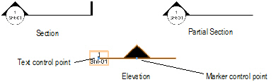
 Section
Lines and Section-Elevation Markers
Section
Lines and Section-Elevation MarkersSection lines and section-elevation markers look very similar on a drawing, but they are created differently.
A section line is automatically created when a section viewport is created. The section line graphically indicates the cutting plane of the section viewport and shows the orientation of the section view. Specify the graphic properties of the section line (such as the marker style), when you create the section viewport. To access a section line from its section viewport, click Section Line Instances from the Object Info palette (see “Section Line Instances” on page 1627).
A section line that has been pasted from a copy, duplicated, or mirrored from a section line that was associated with a section viewport becomes an “unlinked” section line. It displays with black and yellow stripes and the Section Viewport field in the Object Info palette displays “Not Linked.”
A section-elevation marker is graphically similar to a section line, but it is not linked to any viewport. Use the Section-Elevation Marker tool from the Dims/Notes tool set to insert a marker, as a reference line graphic for sections and elevations, or as a cutting plane graphic. Select the Preferences option from the Tool bar to specify the graphic properties of the object before you create it.
After creation, edit both section lines and section-elevation markers as follows:
• Use the Object Info palette to edit the graphic properties (such as the marker style).
• Use the Attributes palette to apply attributes (such as the fill or pen color).
• Use options on the Text menu to control the text appearance (such as the font or size), or assign a text style.
• Use the Selection or Reshape tool to edit the objects (see “Modifying Section Lines Graphically” on page 1652).

To insert a section-elevation marker:
1. Select the Section-Elevation Marker tool from the Dims/Notes tool set.
2. Select the Preferences option from the Tool bar, and set the default parameters for section-elevation markers.
3. Click to place one end of the section-elevation marker.
4. To insert a single-segment marker, drag to determine the marker length.
To insert a multi-segment marker, click to define each segment. Because a multi-segment marker is a polyline, the methods of drawing and editing polylines apply (see “Creating Polylines” on page 294).
5. Double-click to finish placing the section-elevation marker.
~~~~~~~~~~~~~~~~~~~~~~~~~
 Section Line
Instances
Section Line
InstancesSection line instances associated with a section view can be added to or deleted from design layers or viewport annotations. In addition, the Section Line Instances dialog box provides an easy way to navigate from a section viewport to its associated section lines.
To edit section line instances or navigate to a section line:
1. Select the section viewport whose section line you want to navigate to or edit.
2. Click Section Line Instances from the Object Info palette.
The Section Line Instances dialog box opens.
Click to show/hide the parameters.
3. To add another instance of the section line to a different design layer or to the annotation for a different viewport, click in the column next to that design layer or viewport, and then click OK. Or, to remove a section line instance from a layer or viewport, click the checked column (which removes the check mark), and then click OK.
Deleting all section line instances does not delete the section viewport, and new instances can be created at any time. However, deleting a section viewport deletes all section line instances.
4. The section line instances can also be used as a navigation tool to access a particular section line. Select the section line and click Activate to switch to the design layer or viewport; the section line is selected for any modifications.
To return from a section line instance to the associated section viewport, click Navigate to Section Viewport from the Object Info palette of a selected section line.
~~~~~~~~~~~~~~~~~~~~~~~~~
 Creating
Section Viewports from Unlinked Section Lines
Creating
Section Viewports from Unlinked Section LinesAn unlinked (orphan) section line is disconnected from its associated section viewport, possibly because the section line was pasted from a copy, duplicated, or mirrored. It displays as a black and yellow line, and “Not Linked” is displayed in Section Viewport on the Shape tab of the Object Info palette.
Section viewports can be created from unlinked section lines located on a design layer, sheet layer, or while in edit annotation mode.
To create a section viewport from an unlinked section line:
1. Select the unlinked section lines. If on a sheet layer, include the viewport to be sectioned in the selection set.
Each selected section line creates a new section viewport.
2. Select View > Create Section Viewport.
The Create Section Viewport dialog box opens (see “Creating Section Viewports” on page 1620). If multiple unlinked section lines were selected, the parameters specified apply to all section viewports created.
3. Click OK to create a section viewport for each selected section line.
~~~~~~~~~~~~~~~~~~~~~~~~~
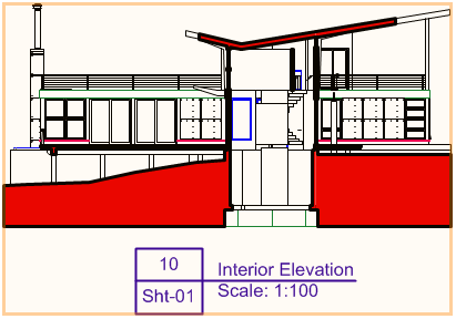
 Creating
and Sectioning Elevation Views
Creating
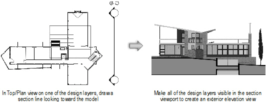
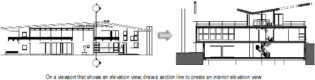
and Sectioning Elevation ViewsSection viewports are useful for creating images that show multiple design layers from a certain point of view.
For example, to show an exterior elevation of a building model, draw a section line outside of the model on one of the design layers and make all of the necessary layers visible in the section viewport. To show an interior view of the same model, do the same thing, but draw the section line through the model at the appropriate location.
Or, if you already have a (non-sectioned) sheet layer viewport that shows multiple design layers in an elevation view, you can draw the section line through the viewport at the appropriate location.
~~~~~~~~~~~~~~~~~~~~~~~~~
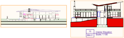
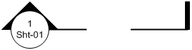
 Creating
Detail Viewports
Creating
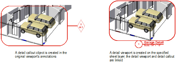
Detail ViewportsThe Create Detail Viewport command creates a cropped sheet layer viewport that shows a detail view of any part of a drawing. A detail viewport can be created from a design layer, another sheet layer viewport, or a section viewport.
The crop object used to create the detail viewport becomes a callout object that is linked to the detail viewport for easy navigation between layers. If the detail callout object is moved or reshaped, the detail viewport is updated accordingly. Additionally, the detail callout is automatically labeled with the drawing number and sheet number of the detail viewport. If the detail viewport is renumbered or moved to another layer, the callout marker is updated automatically.
To create a detail viewport:
1. Create a crop object on a design layer (in Top/Plan view), on a sheet layer viewport (sectioned or not), or inside a viewport annotation group.
2. Select the crop object and then select View > Create Detail Viewport.
The Create Detail Viewport dialog box opens. Different options are available, depending on where the crop object is located (design layer, viewport, or section viewport). Specify the desired parameters.
Click to show/hide the parameters.
3. Click OK to close the Create Detail Viewport dialog box. The specified sheet layer is activated, and the detail viewport is placed in the center of the sheet.
Additionally, the original crop object is converted into a detail callout object. If the detail viewport was created from a design layer, the detail callout is created on the design layer. If the detail viewport was created from a viewport, the detail callout is created in the annotation space of that viewport. The callout includes the drawing number and sheet number of the detail viewport associated with it.

4. You can create additional instances of the callout on other design layers or in the annotations of other viewports, if needed. See “Detail Callout Instances” on page 1631.
5. To delete a detail viewport and its associated callout, delete the viewport.
Click here for a video tip about this topic (Internet access required).
~~~~~~~~~~~~~~~~~~~~~~~~~
 Detail Callout
Instances
Detail Callout
InstancesDetail callout instances associated with a detail viewport can be added to or deleted from design layers or viewport annotations. In addition, the Detail Callout Instances dialog box provides an easy way to navigate from a detail viewport to its associated detail callout.
To edit detail callout instances or navigate to a detail callout:
1. Select the detail viewport whose callout you want to navigate to or edit.
2. Click Detail Callout Instances from the Object Info palette.
The Detail Callout Instances dialog box opens.
Click to show/hide the parameters.
3. To add another instance of the detail callout to a different design layer or to the annotations for a different viewport, click in the column next to that design layer or viewport, and then click OK. Or, to remove a detail callout instance from a layer or viewport, click the checked column (which removes the check mark), and then click OK.
Deleting all detail callout instances does not delete the detail viewport, and new instances can be created at any time. However, deleting a detail viewport deletes all detail callout instances.
4. The detail callout instances can also be used as a navigation tool to access a particular callout. Select the detail callout and click Activate to switch to the design layer or viewport; the detail callout is selected for any modifications.
To return from a detail callout instance to the associated detail viewport, click Navigate to Viewport from the Object Info palette of a selected detail callout.
~~~~~~~~~~~~~~~~~~~~~~~~~
Once it has been created, edit the viewport in the Object Info palette, or select Properties from the viewport’s context menu to open the Properties dialog box. Edit the parameters as needed.
A viewport is assigned to the None class when it is created, and its visibility is controlled by the class settings when that class is not active.
Click to show/hide the parameters.
Once a section viewport is created (Vectorworks Design Series required), you may need to add or remove items that display in the section view. To do so, first use the Convert to Lines, Convert to Polygons, or Convert to Group command to convert the viewport to another form. (This conversion results in a group of lines and other primitives; it is no longer a viewport and can’t be updated to reflect drawing changes.) The conversion will produce different results, depending on which command is used and on how the viewport is rendered at the time of the conversion.
~~~~~~~~~~~~~~~~~~~~~~~~~
Parameters display on the Object Info palette for selected section lines and section-elevation markers. Many of these parameters also display on the Section Line Settings dialog box, which you can access when you create a section viewport. Edit the parameters as needed.
Click to show/hide the parameters.
~~~~~~~~~~~~~~~~~~~~~~~~~
 Properties
of Detail Callouts
Properties
of Detail CalloutsParameters display for selected detail callouts on the Object Info palette. Many of these parameters also display on the Detail Callout Settings dialog box, which you can access when you create a detail viewport. Edit the parameters as needed. If there are multiple instances of the detail callout, all instances are updated.
Click to show/hide the parameters.
~~~~~~~~~~~~~~~~~~~~~~~~~
To access additional sheet layer viewport parameters, click Advanced Properties from the Object Info palette or Properties dialog box of a selected viewport. The Advanced Viewport Properties dialog box opens. These settings affect the viewport display only; they do not change the original design layer(s). Edit the parameters as needed.
Click to show/hide the parameters.
~~~~~~~~~~~~~~~~~~~~~~~~~
 Advanced
Design Layer Viewport Properties
Advanced
Design Layer Viewport PropertiesTo access additional design layer viewport parameters, click Advanced Properties from the Object Info palette of a selected viewport. The Advanced Viewport Properties dialog box opens. These settings affect the viewport display only; they do not affect the original design layer(s). Edit the parameters as needed.
Click to show/hide the parameters.
~~~~~~~~~~~~~~~~~~~~~~~~~
 Advanced
Section Viewport Properties
Advanced
Section Viewport PropertiesAdvanced properties define the extent and attributes of the sheet layer or design layer section viewport. Specify them when the viewport is created, or after the viewport has been created; edit the properties from either the Object Info palette or the Properties dialog box.
To specify the advanced properties of a section viewport:
1. From the Create Section Viewport dialog box, click Advanced Section Properties.
Alternatively, select the viewport, and then from the Object Info palette or the Properties dialog box, click Advanced Properties.
The Advanced Section Properties dialog box opens.
2. Click the Extent tab to specify either an infinite section view, or the length, depth, and height of a finite section viewport.
Finite sections are useful when you want to create interior elevations. For example, draw a section line across a particular room of a building, and set the layer visibility only for the room’s floor to create an interior elevation of only that room. For an even more precise interior elevation, use a clip cube to create the section viewport; the extents are automatically set according to the clip cube’s shape.
Click to show/hide the parameters.
3. Click the Attributes tab to specify the appearance of objects on and beyond the section plane. Objects on the section plane can maintain an individual profile, or can be divided into structural and non-structural groups to display them differently according to class settings.
Click to show/hide the parameters.
4. Click the Display tab to specify the section viewport display properties.
Click to show/hide the parameters.
5. Click OK to close the dialog box and save the changes.
~~~~~~~~~~~~~~~~~~~~~~~~~
There are several ways to modify viewports; their appearance can be completely different from the original design layers, for presentation purposes.
• Modify the settings for the viewport in the Object Info palette.
• Modify the viewport with various 2D and 3D tools and commands.
• Crop the viewport.
• Edit the design layer(s) that display in the viewport.
• Add annotations and dimensions to the viewport.
• Edit or delete a linked Renderworks camera (Renderworks required).
• Change the properties of the viewport’s layers and classes.
~~~~~~~~~~~~~~~~~~~~~~~~~
A sheet layer viewport can be edited like most 2D objects. For information on editing tools and commands, see “Editando Objetos” on page 995. 3D tools cannot be used on sheet layers. However, a 3D object can be copied from a design layer and pasted on a sheet layer. A design layer viewport (Vectorworks Design Series required) cannot be pasted on a sheet layer.
• Use the Cut, Copy, and Paste commands to copy or paste a viewport on its original sheet layer or another sheet or design layer. Use the Selection tool to drag a viewport to a new position (or edit the X- and Y-axis positions in the Object Info palette). Press the Delete key to delete a selected viewport.
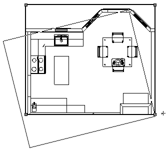
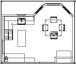
• Use the Move and Rotate commands and the Rotate and Mirror tools to move, rotate, or mirror a viewport. The viewport can be split by the Split tool (in Line Split mode), and clipped with the Clip tool.
• Use the Scale Objects command to scale a viewport. Any crop objects in the viewport are also scaled, as are annotations and dimensions. Viewport text, however, is not scaled unless Scale Text is selected in the Scale Objects dialog box.
• To scale a viewport with the mouse, select the viewport and use the Modify > Group command to turn it into a group object. Click and drag a handle to resize the viewport as needed. Then use the Modify > Ungroup command to change it back into a viewport object.
• Use the Modify > Lock and Modify > Unlock commands to lock and unlock viewports.
• Use the Eyedropper tool to transfer attributes from one viewport to another; see “Transferindo Atributos” on page 1093.
• Use 2D drawing tools on sheet layers to create borders, title blocks, and so on.
• A sheet layer viewport can be copied and pasted into an image-editing application. The dpi setting of the sheet layer affects the resolution of the pasted image. Depending on the platform and the image-editing application, the resolution of the pasted image may still not be optimal; in this case, the File > Export Image File command offers control over the exported area, dimensions, resolution, and file type.
~~~~~~~~~~~~~~~~~~~~~~~~~
To edit a design layer that is displayed in a viewport:
1. Select the viewport.
2. Select Modify > Edit Viewport.
Alternatively, right-click (Windows) or Ctrl-click (Mac) on a viewport, and select Edit from the context menu.
The Edit Viewport dialog box opens. The options available depend on whether the viewport is on a sheet layer or design layer (Vectorworks Design Series required).
Click to show/hide the parameters.
3. Click Design Layer and select the design layer to edit from the list.
Alternatively, right-click (Windows) or Ctrl-click (Mac) on a viewport and select Edit Design Layer from the context menu to activate the design layer of the right-clicked object (if the right-clicked object does not belong to a design layer, the Edit Viewport dialog box opens).
4. Select the editing options:
• Select Display using Viewport Attributes to view the design layer with the viewport attributes (orientation, projection, render mode, and layer and class visibilities). A rendered viewport displays the original design layer with the viewport’s render mode; however, the design layer’s render mode options for that mode are used.
• Select Add Reference Crop Object to view the crop object on the design layer during editing. However, because the crop object is added to the design layer, it could become visible in other viewports that reference that area of the design layer.
• Select Navigate Back to Viewport to easily return to the viewport when you are finished with the design layer edits. A colored border around the drawing window indicates that you are in an editing mode. The Return to Viewport button is visible in the top right corner of the drawing window.
• If this is a section viewport, select Display with Clip Cube to use a clip cube while editing the design layer.
5. Click OK to activate the selected design layer.
6. If you selected Navigate Back to Viewport, a colored border displays around the drawing window. Do one of the following when your edits are complete:
• Click Return to Viewport to return to the viewport. This saves changes to drawing objects, but it does not save clip cube edits.
• Press Shift + Esc to exit to the design layer instead of exiting to the viewport. Alternatively, right-click (Windows) or Ctrl-click (Mac) in the drawing area, and select Exit Viewport from the context menu.
• If the viewport has a clip cube, right-click (Windows) or Ctrl-click (Mac) the vertical cube face where the section line is located; select Update Section Viewport to save the clip cube edits. Then either click Return to Viewport, or select Exit Viewport from the context menu to exit editing mode.
• If the viewport has a clip cube, right-click (Windows) or Ctrl-click (Mac) any vertical cube face other than where the section line is located; select Create Section Viewport to create a new section viewport with its section line located at that cube face.
~~~~~~~~~~~~~~~~~~~~~~~~~
To crop a viewport:
1. Select the viewport.
2. Select Modify > Edit Viewport. The Edit Viewport dialog box opens (see “Editing a Design Layer Displayed in a Viewport” on page 1645 for a description of the dialog box parameters).
3. Click Crop.
Choose whether to display the viewport outside of the crop area. Select Display Viewport Outside Crop to view the rest of the viewport; select Gray Outside Crop to view the area outside of the crop in gray. These options make drawing and editing easier, since objects outside the crop can be snapped to.
To view other layer objects while in Edit Crop mode, select Show other objects while in editing modes on the Display tab of the Vectorworks preferences (see “Aba de Visualização” on page 48).
4. Click OK to enter Edit Crop mode.
Alternatively, right-click (Windows) or Ctrl-click (Mac) on a viewport and select Edit Crop from the context menu.
A colored border around the drawing window indicates that you are in an editing mode. The Exit Viewport Crop command becomes available from the Modify menu, and the Exit Viewport Crop button is visible in the top right corner of the drawing window.
5. Create a 2D object such as a rectangle, circle, or polyline. The 2D object must define an area; for example, a 2D line cannot be used. Position the 2D object to delimit the new viewport display area. The fill of a viewport cropping object is always None; however, the pen style can be set from the Attributes palette while in Edit Crop mode. Move and resize the 2D object as needed.
Use the Flyover tool to adjust the view as necessary (see “Flyover” on page 1140).
The bounding box of the crop object is also the perspective clip rectangle, if the viewport is in Perspective projection. Reshaping the crop object changes the perspective clip rectangle as well.

6. Click Exit Viewport Crop to return to the sheet layer or design layer.
7. The cropped viewport displays; in the Object Info palette, the Crop status changes to Yes.
8. To change, replace, or delete the crop object, select the viewport and then select Modify > Edit Viewport to re-enter Edit Crop mode. Alternatively, right-click (Windows) or Ctrl-click (Mac) and select Edit from the context menu.
To change the visibility of the crop object, change the Crop Visible setting in the Object Info palette.
~~~~~~~~~~~~~~~~~~~~~~~~~
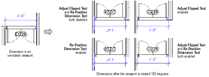
Use the Edit Annotation mode to add annotations and dimensions in viewports, and to edit those annotations and dimensions later on.
To add annotations, including dimensions, to a viewport:
1. With the viewport’s sheet layer active, select the viewport by clicking on it with the Selection tool.
2. Select Modify > Edit Viewport. The Edit Viewport dialog box opens (see “Cropping Sheet Layer or Design Layer Viewports” on page 1648 for a description of the dialog box parameters).
3. Click Annotations and then click OK to enter Edit Annotation mode.
Alternatively, right-click (Windows) or Ctrl-click (Mac) on a viewport and select Edit Annotations from the context menu.
A colored border around the drawing window indicates that you are in an editing mode. The Exit Viewport command becomes available from the Modify menu, and the Exit Viewport Annotation button is visible in the top right corner of the drawing window.
4. Use the various dimension tools from the Dims/Notes tool set to add dimensions to the viewport (see “Cotas e Anotações” on page 1183). The dimension tools snap to the objects in the viewport as if you were dimensioning the design layer. The dimensions are automatically updated if the design layer object changes.
Annotations are 2D objects that are placed on the screen plane. Therefore, a 2D object in the viewport must be dimensioned in Top/Plan view. A 3D object can be dimensioned in any view, but you must align the face that is to be dimensioned with the screen plane to get an accurate measurement.
To view other objects on the sheet layer while in Edit Annotation mode, select Show other objects while in editing modes on the Display tab of the Vectorworks preferences (see “Aba de Visualização” on page 48).
Text, callouts, and other annotations, as well as 2D objects, can be added to the viewport. The Vectorworks Design Series products contain additional annotation objects.
The stacking order of selected annotations can be changed with the Modify > Send commands. To add graphical annotations to a viewport rendered with Hidden Line, use the inner or outer boundary mode of the 2D Polygon tool (see “2D Polygon Tool” on page 299).
Annotations are in viewport scale, not sheet layer scale.
5. Click Exit Viewport Annotation to exit Edit Annotation mode and return to the sheet layer.
6. To change, replace, or delete the viewport annotations, select the viewport and then select Modify > Edit Viewport to re-enter Edit Annotation mode.
To change the visibility of the crop object, change the Crop Visible setting in the Object Info palette.
~~~~~~~~~~~~~~~~~~~~~~~~~
 Editing
a Linked Renderworks Camera
Editing
a Linked Renderworks CameraYou can edit a linked Renderworks camera, to change the associated sheet layer viewport’s view.
To edit a linked Renderworks camera:
1. Select the viewport.
2. Select Modify > Edit Viewport. The Edit Viewport dialog box opens (see “Editing a Design Layer Displayed in a Viewport” on page 1645 for a description of the dialog box parameters).
3. Click Camera.
4. An alert dialog box opens. Click OK to enter Edit Renderworks Camera mode.
Alternatively, right-click (Windows) or Ctrl-click (Mac) on a viewport and select Edit Camera from the context menu.
A colored border around the drawing window indicates that you are in an editing mode. The Exit Renderworks Camera command becomes available from the Modify menu, and the Return to Viewport button is visible in the top right corner of the drawing window.
5. The design layer that was active when the viewport was created is active, and the linked Renderworks camera object is selected. Edit the camera view as described in “Adjusting the Camera View” on page 1155.
The camera can be deleted. The view and projection parameters are controlled by the viewport if the camera is deleted.
If no Renderworks camera is linked to the viewport, select a camera to be linked. Alternatively, the view can be manipulated with the standard view tools (such as the Flyover tool, zoom level, and View menu commands), changing the viewport view upon exit.
6. Click Return to Viewport to return to the viewport once the Renderworks camera has been edited or deleted. The viewport’s view, projection, and perspective distance are updated.
~~~~~~~~~~~~~~~~~~~~~~~~~
 Modifying
Section Viewports and Section Lines
Modifying
Section Viewports and Section LinesSection viewports can be modified, cropped, annotated, and updated, the same as regular sheet layer viewports. See “Modifying Viewports” on page 1644 and “Updating Viewports” on page 1661.
The appearance of a section viewport can be completely customized, from the items it displays to the attributes of those items. Copies of a section viewport on a sheet layer can look completely different. Changes to a section viewport’s appearance can be made by several methods; after changes are made, update the section viewport by clicking Update in the Object Info palette.
Modification |
Method |
Description |
|---|---|---|
Change the section view |
Click Advanced Properties from the Object Info palette of a selected section viewport, and modify the section view from the Extent tab |
|
Change the view attributes |
Click Advanced Properties from the Object Info palette of a selected section viewport, and modify the attributes of the view from the Attributes tab |
|
Change the view direction of the section line |
Click Reverse Direction from the Object Info palette of a selected section viewport |
|
Change the cross section appearance for sectioned items |
The cross section appearance is set by the Section Style class. Edit the class to change the appearance of sectioned items. If the Section Style class is made invisible, the cross sections are not displayed. |
|
Override the layer settings from the design layer |
Click Layers from the Object Info palette of a selected section viewport, and override the layer properties. Unlike a regular sheet layer viewport, the design layer stacking order in the section viewport cannot be changed. |
“Changing the Layer Properties of Sheet Layer or Design Layer Viewports” on page 1655 |
Override the class settings from the design layer |
Click Classes from the Object Info palette of a selected section viewport, and override the class properties of “by class” objects |
“Changing the Class Properties of Sheet Layer or Design Layer Viewports” on page 1657 |
Change the location of the section line |
Change the location of the section line with the Selection tool, and update the section viewport |
|
Create section viewports from unlinked section lines |
Select the unlinked section lines and then select the Create Section Viewport command to create section viewports from the section lines |
“Creating Section Viewports from Unlinked Section Lines” on page 1627 |
Add additional section line instances to design layers or viewports |
Click Section Line Instances from the Object Info palette of a selected section viewport, and specify the design layers or viewports where section line instances should display |
|
Change the section line length, position, or type |
Change the section line with the Selection tool or the Reshape tool, and update the section viewport |
|
Change the depth of a finite section |
The depth can be changed graphically or by modifying the Depth Range in the Advanced Properties of the section viewport |
“Modifying Section Lines Graphically” on page 1652, or “Advanced Section Viewport Properties” on page 1641 |
~~~~~~~~~~~~~~~~~~~~~~~~~
 Modifying
Section Lines Graphically
Modifying
Section Lines GraphicallyIn addition to modifying section line parameters as described in “Section Lines and Section-Elevation Markers” on page 1626, the section line can be modified by changing its location, length, or shape.
To modify a section line:
1. Navigate to the section line by clicking Section Line Instances from the Object Info palette of a selected section viewport.
2. The section line is automatically selected for modification.
• Move the section line to a new location with the Selection tool
• Shorten, lengthen, or rotate the line by dragging an end point with the Selection tool
• Add vertices and change a straight section line to a broken section line with the Reshape tool
• Reshape the section line with the Reshape tool
3. A section view with a finite depth has a special control point on a dashed line. To adjust the depth, drag the control point with the Selection tool.
4. Return to the section viewport by clicking Activate Section Viewport from the Object Info palette. Click Update from the Object Info palette to reflect the section line changes in the section view.
~~~~~~~~~~~~~~~~~~~~~~~~~
 Editing
Detail Viewport Drawing Labels
Editing
Detail Viewport Drawing LabelsAfter creation, the detail viewport drawing label may be edited, either to change its appearance, or to change the information that it displays. Edit the drawing label from within the detail viewport’s annotation space.
If Use Automatic Drawing Coordination is selected in document preferences, a change to the Drawing Number field for the detail viewport automatically changes the field for the viewport’s drawing label, and vice versa. Additionally, if Text Auto-Fill is selected for the detail callout, a change to the Drawing Number field for the viewport automatically changes the field for the detail callout.
There are several ways to change the appearance of a detail viewport drawing label.
• Use the Attributes palette to change the label’s line color or thickness
• Use the Object Info palette to change the object properties
• Use the Text menu to change the attributes of the label text (or apply a text style to it)
• Use the Selection tool to adjust the label position
To edit a detail viewport drawing label:
1. Select the detail viewport and then select Modify > Edit Viewport. The Edit Viewport dialog box opens.
2. Click Annotations and then click OK to enter Edit Annotation mode.
Alternatively, right-click (Windows) or Ctrl-click (Mac) on a viewport and select Edit Annotations from the context menu.
A colored border around the drawing window indicates that you are in an editing mode. The Exit Viewport command becomes available from the Modify menu, and the Exit Viewport Annotation button is visible in the top right corner of the drawing window.
3. Select the drawing label and edit it as needed. The parameters in the Object Info palette are described in “Creating Drawing Labels” on page 1238.
4. Click Exit Viewport Annotation to exit Edit Annotation mode and return to the sheet layer.
~~~~~~~~~~~~~~~~~~~~~~~~~
After creation, the detail callout may be edited, either to change the appearance of the callout itself, or to change the view in the detail viewport that is linked to the detail callout. The edit method depends on where the detail callout was created. If the callout object was created on a design layer, select the callout and edit it directly. If the callout object was created within a viewport’s annotation space, select the viewport and edit its annotations (see “Editing a Detail Callout in a Viewport” on page 1654).
If Use Automatic Drawing Coordination is selected in document preferences, a change to the Drawing Number field for the detail viewport automatically changes the field for the viewport’s drawing label, and vice versa. Additionally, if Text Auto-Fill is selected for the detail callout, a change to the Drawing Number field for the viewport automatically changes the field for the detail callout.
There are several ways to change the appearance of a detail callout object.
• Use the Attributes palette to change the crop object’s line color, thickness, or type
• Use the Object Info palette to change the object properties (see “Properties of Detail Callouts” on page 1638)
• Use the Text menu to change the attributes of the marker text (or apply a text style to it)
• Use the Selection tool to adjust the marker position
You can also adjust the shape or location of the callout object, which will change the contents of the detail viewport associated with the callout. If there are multiple instances of the detail callout, all instances are updated.
• Use the Selection tool to move the entire callout
• Use the Reshape tool to reshape the callout object
If the callout was created from a viewport, the callout object cannot be edited directly because it is in the viewport’s annotation space.
To edit a detail callout object in a viewport:
1. Select the original viewport and then select Modify > Edit Viewport. The Edit Viewport dialog box opens.
2. Click Annotations and then click OK to enter Edit Annotation mode.
Alternatively, right-click (Windows) or Ctrl-click (Mac) on a viewport and select Edit Annotations from the context menu.
A colored border around the drawing window indicates that you are in an editing mode. The Exit Viewport command becomes available from the Modify menu, and the Exit Viewport Annotation button is visible in the top right corner of the drawing window.
3. Select the detail callout and edit it as needed. The parameters in the Object Info palette are described in “Properties of Detail Callouts” on page 1638.
4. Click Exit Viewport Annotation to exit Edit Annotation mode and return to the sheet layer.
~~~~~~~~~~~~~~~~~~~~~~~~~
The viewport’s layer visibility, opacity, stacking order, and colors can be changed from the sheet layer or the design layer (Vectorworks Design Series required). Other viewports, as well as the design layer properties, are not affected. The viewport attributes can be tailored as desired for presentation; several copies of the same viewport can appear completely different.
To change the viewport layer properties:
1. Select the viewport.
2. From the Object Info palette, click Layers.
The Viewport Layer Properties dialog box opens.Change layer visibilities and/or make layer attribute overrides for the selected viewport.

Click to show/hide the parameters.
3. To override the layer properties (for viewport display), select one or more viewport layers and click Edit.
Alternatively, double-click on a viewport layer to edit it.
The Edit Viewport Design Layers dialog box opens.
4. The same parameters apply when you create a design layer (see “Setting Design Layer Properties” on page 161); for viewport layers, only the stacking order, transfer mode or opacity, and colors can be edited. These edits apply to the current viewport only, though they can be transferred to other viewports with the Eyedropper tool.
The viewport layer colors can be controlled separately from the design layer colors, for flexible presentation output. Click Colors to override the fill and pen colors for the selected viewport layer. To see the effects of the color override, Use Layer Colors must be selected in the Viewport Layer Properties dialog box for the selected viewport. This is similar to the way that Use Layer Colors must be selected in document preferences to see the layer color settings for a design layer, as described in “Setting the Design Layer Color” on page 166.
5. Click OK to return to the Viewport Layer Properties dialog box.
Click Preview to evaluate the results of the property changes.
6. Click OK to return to the sheet layer or design layer.
~~~~~~~~~~~~~~~~~~~~~~~~~
The class visibilities and attributes of a selected viewport can be changed from the sheet layer or the design layer. This does not change the class properties or the class visibility for the original design layers or for other viewports. The viewport attributes can be tailored as desired for presentation; several copies of the same viewport can appear completely different.
To override viewport class properties:
1. Select the viewport.
2. From the Object Info palette, click Classes.
The Viewport Class Properties dialog box opens. The dialog box functionality is slightly different for referenced (Vectorworks Design Series required) and non-referenced (internal) viewports. Change class visibilities and/or make class attribute overrides for the selected viewport.
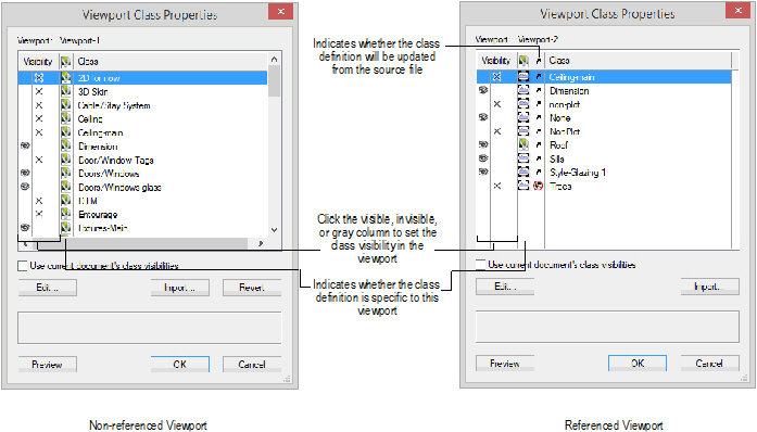
Click to show/hide the parameters.
3. Click OK to apply the class visibility and attribute changes to the selected viewport.
~~~~~~~~~~~~~~~~~~~~~~~~~
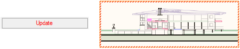
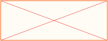
The status of a viewport or section line is indicated visually.
Viewport Status |
Description |
|---|---|
Normal |
A normal, up-to-date viewport displays with orange highlighting when selected
|
Out of date |
When the objects in a viewport have changed since the viewport was created or last updated, the viewport becomes out of date. An out-of-date viewport is indicated by red text on the Update button on the viewport’s Object Info palette. Optionally, an out-of-date viewport also displays with a red and white striped border around the viewport (see “Aba Visualização” on page 57).
|
Empty |
A viewport displays as a red “X” when the associated design layer contains no objects or the objects are hidden, or when the associated design layer is set to “invisible”
|
Unlinked (section line) (Vectorworks Design Series required) |
An unlinked section line (disconnected from its associated section viewport, possibly because the section line was pasted from a copy, duplicated, or mirrored) displays as a black and yellow line, and “Not Linked” is displayed in the Object Info palette
|
~~~~~~~~~~~~~~~~~~~~~~~~~
Changes that affect the appearance of a viewport are automatically updated for a wireframe viewport. However, if changes require the viewport to be rendered again, the viewport will be displayed as an out-of-date viewport.
If a sheet layer with an out-of-date viewport is printed, a message prompts you to either print the viewport as an out-of-date viewport or update the viewport(s) on the sheet layer before printing.
Rendered viewport updates occur in the background for Renderworks render modes; you can continue working in the file while the viewports are updating. See “Background Rendering” on page 1590.
To update selected viewports:
1. Select the viewport(s).
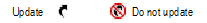
2. On the Object Info palette, click Update. Alternatively, select View > Update Selected Viewports.
Alternatively, right-click (Windows) or Ctrl-click (Mac) on the viewport and select Update from the context menu.
3. The selected viewports are updated.
To update all the viewports in the file:
1. Select View > Update All Viewports.
2. All viewports on all sheet layers are updated.
To cancel viewport updates:
To cancel the updates of all viewports, including those queued to update for background rendering:
1. Select View > Cancel All Viewport Updates.
2. The updates are canceled.
~~~~~~~~~~~~~~~~~~~~~~~~~


 ). If the viewport class
does not exist in the current file, it will be imported. If
the class is also set to update from the source file (
). If the viewport class
does not exist in the current file, it will be imported. If
the class is also set to update from the source file (