Organizando Seu Desenho
Organizando
o Desenho
Quando
estiver criando o desenho de um projeto, comece desenvolvendo uma estrutura
de camadas e classes, e ao mesmo tempo crie também um sistema de associação
dos itens apropriados a essas camadas e classes. Uma camada no Vectorworks
é basicamente um container de itens. As camadas podem ser comparadas a
folhas de papel; cada item “pertence” a uma camada, e da mesma forma que
um item desenhado a mão pertence a uma folha de papel. (Além disso, no
Vectorworks Architect as camadas de projeto podem pertencer aos andares
do prédio.)
Uma
classe, no entanto, é um atributo de um objeto. As Classes “passam” por
todas as camadas, e permitem que você controle os atributos e visibilidade
dos objetos através das múltiplas camadas. Dê a saída de elementos específicos
de um desenho rápida e facilmente, selecionando as camadas e classes apropriadas
para exibição.
O
Vectorworks também fornece maneiras de salvar a visualização atual do
desenho com histórico e vistas salvas, e apresentar os desenhos com viewports.
Vistas e históricos fornecem uma visualização “em uma parte do tempo”
do desenho. Históricos guardam vistas do desenho em uma relação de forma
similar aos navegadores de internet, enquanto que vistas salvas guardam
as configurações de exibição atual de visibilidade de camadas e classes.
Os Viewports são criados em camadas especiais chamadas de camadas de folha
e são usadas para exibir as vistas finais de um desenho para uma apresentação
ao cliente.
~~~~~~~~~~~~~~~~~~~~~~~~~
A Janela de Diálogo Organização
Administrando Camadas
Setting Up the Building Structure with Stories
Classes
Design Series Layers, Classes, and Viewport
Standards
Saved Views
Setting Class and Design Layer Options
Setting Visibilities in the Organization
Dialog Box
The Visibility Tool
The Navigation Palette
Grupos de Trabalho e Referenciamento
A Janela
de Diálogo Organização
Crie
e gerencie os elementos estruturais de desenho (camadas de projeto, camadas
de folha, classes, viewports e vistas) usando a janela de diálogo Organização.
Esta janela possui funções especializadas para organizar e selecionar
itens em listas. Veja “Funcionalidade
da Caixa de Listagem” na página 41.
Para usar
a janela de diálogo Organização:
1.Selecione Organizar
> Organização.
Alternativamente clique em Classes ou
Camadas na Barra de Visualização,
ou selec ione
Editar Vista no menu de Vistas
Salvas também na Barra de Visualização.
A janela de diálogo Organização aparecerá.
2. Selecione a aba apropriada para o elemento estrutural
do Vectorworks que deseja criar ou editar: Classes, Camadas de Projeto,
Camadas de Folhas, Viewports,Vistas Salvas ou Referencias
No Vectorworks
Architect, a aba Andares também está disponível; veja “Creating
and Managing Stories” na página 168.
3.No
topo da janela, selecione a opção desejada de visualização dos parâmetros:
Detalhes ou Visibilidade.
De
uma forma geral, a opção de visualização Detalhes mostra o estado de cada
elemento, e permite controlar a visibilidade das classes e camadas na
área de desenho; a opção Visibilidade permite controlar a visibilidade
de classes e camadas tanto em viewports como em vistas salvas.
4.Botões
na parte inferior de cada guia fornecem criação e funções de gestão. Como
alternativa, o botão direito do mouse (Windows) ou Ctrl + clique (Macintosh)
em um item da lista para exibir um menu de contexto, que tem a maioria
das mesmas funções que os botões da guia.
Aba Classes
Se uma descrição foi
definida para a classe, ela é exibida em uma dica de tela quando você
posicionar o cursor sobre o nome da classe. No Windows, clique na seta
para divulgação na ponta da tela para recolher ou expandir.
Clique para
mostrar / ocultar os parâmetros.
Aba Camada de Projeto
Os nomes da camadas de
projeto referenciados são exibir em itálico. Se uma descrição foi inserida
para a camada de design, ela é exibida em uma dica de tela quando você
posicionar o cursor sobre o nome da camada. Se a camada é referenciada,
a dica de tela também exibe o nome da camada completo e o nome do arquivo
de origem. No Windows, clique na seta para divulgação na ponta da tela
para recolher ou expandir.
Clique para
mostrar / ocultar os parâmetros.
Aba Andares
Se uma descrição foi
definida para a camada de projeto, ela é exibida em uma dica de tela quando
você posicionar o cursor sobre o nome da classe. No Windows, clique na
seta para divulgação na ponta da tela para recolher ou expandir.
Clique para
mostrar / ocultar os parâmetros.
Aba Viewports
Clique para
mostrar / ocultar os parâmetros.
Aba Vistas Salvas
Clique para
mostrar / ocultar os parâmetros.
Aba Referências
Clique para
mostrar / ocultar os parâmetros.
Clique
aqui para dica em vídeo deste tópico (conexão de internet).
~~~~~~~~~~~~~~~~~~~~~~~~~
Organizando o Desenho
Administrando Camadas
Classes
Saved Views
Grupos de Trabalho e Referenciamento
Exibindo Classes em Ordem
Hierárquica
Na
janela Organização e na paleta Navegação (requer Design Series) as classes
com nomes compostos separados por um traço (como por exemplo Walls-Ext)
podem ser exibidas em ordem hierárquica (em até quatro níveis) da mesma
forma como são exibidas nos menus Classes. Cada nível de classe terá um
cabeçalho de grupo no nível superior quando este for exibido em ordem
hierárquica. Algumas opções estarão disponíveis para controlar a exibição
hierárquica das classes em vários níveis.
Para ativar / desativar
a exibição ordem hierárquica em menus pop-up em todo software Vectorworks:
• Na
guia Sessão da caixa de diálogo Preferências Vectorworks, selecionar /
desmarcar classes de exibição em menus pop-up hierarquicamente para alternar
entre a visualização hierárquica e não hierárquica. Esta definição controla
todos os menus pop-up de todo o software.
Para ativar
a exibição hierárquica:
• Na
aba Classes da janela Organização, clique no botão alternar no canto inferior
direito ou selecione a opção Exibição
Hierárquica para alternar entre as exibições hierárquica e não-hierárquica,
com os itens expandidos ou recolhidos conforme a sua última exibição.
• Na paleta
Navegação (requer Design Series) selecione a opção Exibição Hierárquica no
menu de contexto para alternar entre as exibições hierárquica e não-hierárquica,
com os itens expandidos ou recolhidos conforme a sua última exibição.

Ao exibir
as classes em ordem hierárquica, a ordenação não estará disponível.
Para expandir
ou minimizar um único cabeçalho de grupo de classe na exibição em ordem
hierárquica:
• Clique
na seta de expansão à esquerda do cabeçalho de grupo de classe
• Dê
um duplo clique no cabeçalho de grupo de classe
Para expandir
todas as classes no arquivo ou para minimizar a lista para somente as
classes de nível superior (aquelas sem o traço no nome) e exibir os cabeçalhos
de grupo de classe na exibição de ordem hierárquica:
• Clique
segurando Shift e Option (Macintosh) ou segurando Shift e Alt (Windows)
na seta de expansão à esquerda do cabeçalho de grupo de classe
• Dê
um duplo clique segurando Shift e Option (Macintosh) ou segurando Shift
e Alt (Windows) no cabeçalho de grupo de classe
Os comandos
Expandir Todos e Minimizar Todos realizam as mesmas funções.
Para expandir
ou minimizar todos os subgrupos de classes na ordem de exibição hierárquica:
• Clique
segurando Option (Macintosh) ou segurando Alt (Windows) na seta de expansão
à esquerda do cabeçalho de grupo de classe
• Dê
um duplo clique segurando Option (Macintosh) ou segurando Alt (Windows)
no cabeçalho de grupo de classe
Para gerenciar
as opções de visibilidade na ordem de exibição hierárquica:
• Se
todos os subníveis de classe tiverem as mesmas opções de visibilidade,
então o cabeçalho de grupo de classe também terá a mesma opção de visibilidade.
Caso contrário, a coluna Visibilidade ficará em branco para o cabeçalho
de grupo de classe
• Atribua
ou altere a opção de visibilidade usando a coluna Visibilidade do
cabeçalho de grupo de classe, e os subníveis irão herdar as opções de
visibilidade
~~~~~~~~~~~~~~~~~~~~~~~~~
A Janela de Diálogo Organização
Classes
Funcionalidade da Caixa de Listagem
Importando Estrutura
de Desenho a partir de Standards ou Outros Arquivos
Aspectos
específicos da estrutura de desenho (classes, camadas de folhas, e camadas
de projeto) podem ser importados de um ou mais arquivos existentes. Os
arquivos de onde se importam os dados podem ser arquivos padrão fornecidos
com o Vectorworks, ou outros arquivos que você tenha criado com o Vectorworks.
Os arquivos
gabarito (formato .sta) são localizados na pasta Standards (dentro de
[Vectorworks]/Libraries/Defaults). Os padrões de camadas usam apenas nomes
aprovados e ajustes de classes para aplicações específicas. Classes ou
camada personalizadas podem ser criadas em um documento em branco
e então salvas para um arquivo .sta na pasta Standards. Uma vez colocados
na pasta Standards, estas novas camadas ou classes tornam-se parte da
lista de Standards e são disponíveis quando novas camadas ou classes são
criadas.
Caso algum
de seus arquivos de trabalhos torne-se corrompido, um método possível
de recuperação é o de importar os dados em um novo arquivo. Crie um novo
arquivo e então importe as classes, camadas de folha, e camadas de projeto
(e opcionalmente, objetos de camadas de projeto) a partir do arquivo original
se necessário.
Para importar
estruturas de desenho, use a janela de Organização para criar uma nova
classe, camadas de folha, ou camadas de projeto. Ao contrário de criar
um novo item, entretanto, selecione a opção Importar. Selecione o arquivo
do qual importar a estrutura, e então selecione as classes e camadas específicas
que deseja importar do arquivo. Para camadas de projeto, selecione se
deseja importar objetos na camada também.
Veja “Criando Camadas” na página 157 e
“Creating Classes” na página 172
para detalhes.
Clique
aqui para uma dica de vídeo sobre este tópico (requer acesso
a internet).
Administrando
Camadas
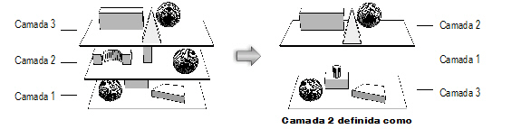
Crie
camadas em um desenho do Vectorworks para obter flexibilidade imediata.
Sobreponha as camadas de projeto em qualquer ordem, ou temporariamente
esconda alguns deles. Reordene as camadas, para mover todos os objetos
contidos em cada camada para outra posição, sem ter que modificar a posição
dos objetos ou seu alinhamento um com outro.
No Vectorworks,
o papel transparente é eletrônico, permitindo a você fazer muito mais
com ele. Para começar, você pode definir uma distância (altura) entre
as camadas, ao invés de colocá-las uma em cima da outra. Com as capacidades
de modelagem 3D do Vectorworks, você pode usar essas camadas para criar
modelos 3D mais complexos. Por exemplo, se você desenhar o primeiro e
segundo pisos, telhado e subsolo de uma casa (cada um em sua própria camada)
você pode não apenas imprimir o desenho em planta 2D de cada uma das camadas,
mas também associar as camadas de desenho umas às outras. Juntas, elas
criarão um modelo completo em 3D de sua casa. Use viewports para mostrar
diversas vistas do projeto final, tanto em camadas de projetos (Design
Series requirido) ou em camadas de folhas, ambas apresentações de camadas
especiais. A camada original permanece inalterada.
As
camadas também possuem muitos outros usos. Mova elementos entre camadas
de projeto, ou mude a escala de uma camada, criando instantaneamente um
detalhe de uma área do desenho sem a necessidade de redesenho. Crie camadas
de projeto com objetos que deverão sempre ser mostrados, ou ainda camadas
que possuem objetos que devem ser visualizados apenas em momentos específicos.
Controle a visibilidade das camadas de projeto para limitar a necessidade
de criação de novos objetos.
No
Vectorworks Architect, as camadas de projeto podem ser associadas a andares;
os andares definem as elevações absolutas no modelo do prédio, enquanto
as camadas podem ser colocadas em uma elevação relativa à do andar. Este
método de organização facilita o gerenciamento das camadas de um prédio
e de certos objetos associados, como paredes e colunas. Veja “Setting
Up the Building Structure with Stories” na página 166.
Use
camadas de projeto para desenhar e modelar seus projetos. Use camadas
de folha para criar uma versão de apresentação do desenho finalizado;
estas camadas podem incluir viewports, carimbos e outras anotações (veja
“Creating Sheet Layer Viewports”
na página 1612).
Quando as
camadas são listadas no Vectorworks, as camadas de folha são listadas
em primeiro, e então as camadas de projeto são listadas. Um separador
divide os dois tipos de camadas na lista.
Camadas
de folha são mostradas na janela com uma área retangular com uma borda
larga em cinza representando a área de impressão, enquanto que camadas
de projeto são mostradas com uma fina linha cinza demarcando área de impressão.
Isto torna mais fácil distinguir rapidamente o tipo de camada em que se
está trabalhando.
Clique
aqui para uma dica de vídeo sobre este tema (conexão com a
internet necessária).
~~~~~~~~~~~~~~~~~~~~~~~~~
Criando Camadas
Atribuindo Objetos para Classes e Camadas
Definindo Propriedades da Camada de Projeto
Setting the Active Layer
Setting Sheet Layer Properties
Setting Class and Design Layer Options
Setting Visibilities in the Organization
Dialog Box
The Visibility Tool
Organizando o Desenho
Criando Camadas
Quando
um novo desenho é criado, ele automaticamente contém uma camada de projeto
vazia com o nome de “Camada de Projeto-1”. Adicione camadas de projeto
ao desenho conforme necessitar para organizá-lo. Adicione camadas de folhas
conforme necessário para a apresentação do desenho. Crie novas camadas,
projeto e camadas de folha, ou importe-as (e, opcionalmente, os objetos
que elas contém) de outros arquivos do Vectorworks (da mesma versão) ou
ainda de arquivos gabaritos. No Vectorworks Design Series, crie um viewports
de camada de projeto para referenciar camadas de projeto de outros arquivos
sem ter que importá-los.

Para
criar uma nova camada:
1.
Para uma maior conveniência,
você poderá criar novas camadas a partir de diversos lugares no Vectorworks.
2. A janela Nova Camada
de Projeto ou Nova Camada de Folha irá se abrir. Crie ou importe uma nova
camada e suas propiedades de um arquivo padrão ou existente nos arquivos
do Vectorworks.
Clique para
mostrar / ocultar os parâmetros.
3.Clique
OK para criar a(s) nova(s)
camada(s) de projeto ou camada(s) de folha.
As
camadas irão aparecer na lista de camadas na janela de Organização, e
também na lista de camadas na Barra de Visualização.
~~~~~~~~~~~~~~~~~~~~~~~~~
Definindo Propriedades da Camada de Projeto
Setting Sheet Layer Properties
Atribuindo Objetos para Classes e Camadas
Setting Class and Design Layer Options
Setting Visibilities in the Organization
Dialog Box
The Visibility Tool
Administrando Camadas
Setting the Active Layer
There are several ways to change the active design layer or sheet layer.
To be able to add, remove, or edit objects on a design
layer, either the layer must be active or the layer options must be set
to allow modifications to other layers (see “Setting
Class and Design Layer Options” na página 188).
Setting the Active Layer
in the Organization Dialog Box
To set the active layer:
1. From the Organization dialog
box, in Details view, select the Design Layers
tab or the Sheet Layers tab.
The active layer is indicated by a check mark to the
left of the Design Layer Name or Sheet Number. The layer also is highlighted
in bold text.
2. To make a different layer active, click the column
to the left of its name/number.
3. Click OK.
The dialog box closes and the active layer displays.
Setting the Active Layer
in the View Bar
To set the active layer:
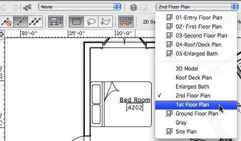
1. Click the Layers list on the
View bar to display a list of all of the sheet layers (top section) and
design layers (bottom section) in the drawing.
On Mac, the active layer is indicated by a check mark;
on Windows, the layer is highlighted in bold text.
2. Click the layer to be activated.
The layers list closes and the active layer displays.
 Setting the Active Layer in the Navigation Palette
To set the active layer:
1. From the Navigation palette,
select the Design Layers tab or the Sheet Layers tab.
The active layer is indicated by a check mark to the
left of the Design Layer Name or Sheet Number. The layer also is highlighted
in bold text.
2. To make a different layer active, click the column
to the left of its name/number.
Alternatively, Right-click (Windows) or Ctrl-click (Mac)
on the layer to be activated and select Activate from
the context menu.
Setting the Active Layer Using the Shortcut Keys
If there is a small number of layers, switch among layers with the Switch active layer/class shortcut key
combination specified in Vectorworks preferences (see “Aba
Edição” na página 47). This selects a layer by moving up or down
through the layer list one layer at a time.
Setting the Active Design
Layer in the Document Context Menu
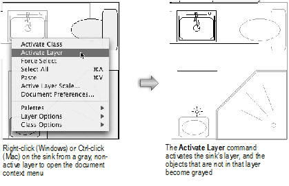
If multiple design layers are set to be visible, and the layer options
are set to show those other layers, the drawing area may display objects
that are on non-active layers. Use the Activate
Layer command to make the layer of one of these objects active.
The Force Select command
on the document context menu also changes the active class and layer (if
necessary), and selects the clicked object.
To set the active design layer:
1. In the drawing area, right-click
(Windows) or Ctrl-click (Mac) a visible object on a non-active design
layer.
2. From the document context menu, select Activate Layer.
The object’s layer becomes active.
~~~~~~~~~~~~~~~~~~~~~~~~~
Definindo
Propriedades da Camada de Projeto
Setting
Sheet Layer Properties
Definindo Propriedades
da Camada de Projeto
Uma
vez criadas, as camadas de projeto passam a ser listadas na aba Camadas
de Projeto da janela Organização, onde diversas propriedades podem ser
definidas e editadas.

Para
editar as camadas:
1.Selecione Organizar
> Organização.
A
janela de Organização irá abrir.
2.
Selecione a aba Camadas de Projeto.
Uma
lista das camadas atuais do desenho serão exibidas em sua ordem de empilhamento.
Dependendo de qual opção de visualização for selecionada na parte superior
da janela de diálogo, tanto detalhes como visibilidades do display de
camadas do projeto. A ordem de empilhamento, visibilidade da área do desenho,
e a camada ativa podem ser alteradas na exibição de detalhes. A visibilidade
de camadas nas viewports e vistas salvas pode ser alteradas na vista Visibilidades.
No produto
Vectorworks Architect, Detalhamento da vista inclui os andares e seus
níveis para cada camada que esteja associada a um andar de um nível.
Camadas
que são importadas de outro arquivo com referenciamento de camada importada
em itálico. Posicione o cursor sobre o nome da camada para exibir uma
dica de tela com o nome da camada completo e o nome do arquivo de origem.
3.
Para alterar outras propriedades da camada, selecione uma ou mais camadas
e clique em Editar para abrir a janela de diálogo Editar Camadas de Projeto.
Clique para
mostrar/ocultar os parâmetros.
~~~~~~~~~~~~~~~~~~~~~~~~~
Definindo a Opacidade da Camada de Projeto
Setting the Design Layer Transfer Mode
Criando Camadas de Fundo
Setting the Design Layer Color
Setting Up the Building Structure with Stories
Alterando a Ordem de Sobreposição
da Camada de Projeto
Camadas de Projetos são
visualizadas e impressas na "Ordem de Sobreposição," de cima
para baixo na janela de diálogo de configuração de Camadas. Inicialmente,
as camadas são "sobrepostas" na ordem em que são criadas, mas
a sua ordem pode ser alterada a qualquer momento.
Alterar a ordem de sobreposição
das camadas de projeto:
1.
Na janela de diálogo Organização, selecione a aba Camadas de Projeto na
exibição de Detalhes para ver a ordem de sobreposição recente. A coluna
# à direita do nome da camada indica a posição atual da camada na pilha,
com 1 sendo a camada superior.
2.
Use um dos seguintes métodos para alterar a ordem de sobreposição da camada:
• A
coluna # deve ser a coluna de classificação atual para alterar a ordem
de sobreposição; Se a lista não estiver ordenada por ordem de sobreposição,
clique no # título da coluna para alterá-lo. Em seguida, clique na coluna
# da(s) camada(s) a serem movidas e arraste-a para cima ou para baixo
na lista. Uma linha horizontal indica onde a(s) camada(s) serão inserida(s)
na ordem atual.
• Selecione
a(s) camada(s) para mover, e clique em Editar (ou clique duas vezes em
uma linha da camada) para abrir a janela de diálogo Editar Camadas de
Projeto. No campo ordem de sobreposição, introduza um número para a nova
posição de ordem de sobreposição da(s) camada(s). Clique em OK para aceitar
as alterações.
3.
A aba Camadas de Projeto exibe a nova ordem de sobreposição. Clique em
OK para fechar a janela de diálogo Organização e salvar as alterações.

Definindo a Opacidade da
Camada de Projeto
Este recurso está disponível
em todos os sistemas Mac, em sistemas Windows apenas quando a preferência
GDI + imagem está habilitada. (Veja "Preferências de Exibição Vectorworks"
na página 48 para obter informações sobre como definir essa preferência.)
Camadas de Projeto têm uma configuração que controla a transparência de
objetos da camada que sobrepõem objetos visíveis em outra camada. Um valor
de opacidade de 100% significa que nada abaixo da camada ativa é visível.
Diminuir o valor de opacidade para aumentar a transparência dos objetos
na camada.
Para definir a Opacidade
de uma Camada de Projeto:
1.
Na janela de diálogo Organização, selecione a aba Camadas de Projeto.
Selecione uma ou mais camadas, e em seguida, clique em Editar.
A janela
de diálogo Editar Camadas de Projeto é exibida.
2.
Arraste o controle deslizante Opacidade para a esquerda para aumentar
a transparência, ou digite um percentual de opacidade (0-100) na caixa
à direita do controle deslizante.
3.
Clique em OK para fechar a janela de diálogo Editar Camadas de Projeto
e clique em OK novamente para fechar a janela de diálogo Organização.
Objetos
individuais também podem ter uma porcentagem de opacidade aplicada, veja
“Atributos de Opacidade” na página 1098.
~~~~~~~~~~~~~~~~~~~~~~~~~
Setting the Design Layer Transfer Mode
Setting the Design Layer
Transfer Mode
This feature is only available on Windows systems. When the GDI+ imaging
preference is disabled, design layers have a setting that controls the
display of layer objects that overlap visible objects in another layer.
(See “Aba de Visualização” na página 48
for information about setting this preference.)
To set the transfer mode for a design layer:
1. From the Organization dialog
box, select the Design Layers tab. Select one or several layers, and then
click Edit.
The Edit Design Layers dialog box opens.
2. Select the desired Transfer
Mode from the list. Click OK to
close the Edit Design Layers dialog box, and then click OK
again to close the Organization dialog box.
Mode |
Description |
Paint |
Makes objects in the new layer solid,
obscuring objects in layers stacked below it (this is the default
setting)

|
Overlay |
Makes it so objects in the new layer do
not obscure stacked layers

|
Invert |
Makes a reversed, or photo-negative image
display when an object in the new layer overlaps an object in
another layer

|
Erase |
Makes objects in the new layer display
all foreground patterns as white and all background patterns as
transparent

|
Not Paint
|
Makes objects in the new layer solid and
inverts any areas that overlap objects in stacked layers

|
Not Overlay |
Makes objects in the new layer transparent
and inverts layer colors

|
Not Invert |
Makes objects in the new layer transparent
and converts any black pixels from overlapping areas to white
and white pixels to transparent

|
Not Erase |
Makes objects in the new layer transparent
and converts any white pixels from overlapping areas to black
and black pixels to transparent

|
Most printer devices do not support all of these modes,
especially PostScript printers and vector devices such as pen plotters.
The Rasterize print output option may
produce the best results for certain transfer modes. The use of color
in transfer modes may produce color blending.
~~~~~~~~~~~~~~~~~~~~~~~~~
Definindo
a Opacidade da Camada de Projeto
Imprimindo
um Arquivo
Setting the Design
Layer Color
The fill and pen color of objects that are drawn on or moved to a design
layer can be controlled by the color settings of the design layer. The
Use layer colors setting in the Document
Preferences dialog box must be turned on (see “Aba
Visualização” na página 57).
These settings are overridden by the Black
and white only option in the Document Preferences dialog box,
even with the Use layer colors option selected.
To control the color of objects by their design layers:
1. From the Organization dialog
box, select the Design Layers tab. Select one or several layers, and then
click Edit.
The Edit Design Layers dialog box opens.
2. Click Colors.
The Color Defaults for Layer dialog box opens.
3. For both the fill and pen, set the Foreground and
Background colors by clicking the appropriate
list and selecting a color from the main Color Menu dialog box. A preview
example is shown at the bottom of the dialog box.
The fill background color controls the appearance of
objects with a solid fill.
4. Click OK.
When the Use layer colors preference
is selected, all objects on the layer are drawn with the specified colors.
Viewports have separate control of layer color (see
“Advanced Sheet Layer Viewport Properties”
na página 1638).
Click
here for a video tip about this topic (Internet access required).
~~~~~~~~~~~~~~~~~~~~~~~~~
Aplicando
Cores
Setting Sheet Layer
Properties
Once created, the sheet layers display on the Sheet Layers tab
of the Organization dialog box, where various layer properties can be
set and edited.
Sheet layers are always at a 1:1 scale, Active Only,
and set to Top/Plan view.

To edit sheet layers:
1. Select Tools
> Organization. Alternatively, click the Layers
button on the View bar.
The Organization dialog box opens.
2. Select the Sheet Layers tab and the Details
view.
The Sheet Layers tab opens, with a list of the current
layers in the drawing. The layer stacking order and the active layer can
be changed in Details view. Visibilities
view does not apply to sheet layers.
3. To change layer properties, select one or more
layers and click Edit to open the Edit Sheet
Layers dialog box.
Click to
show/hide the parameters.
Changing the Sheet Layer
Stacking Order
Sheet layers are viewed and printed in “stacking order,” the top-to-bottom
order in the Organization dialog box. Initially, layers are “stacked”
in the order in which they are created, but their order can be changed
at any time.
To change the stacking order of sheet layers:
1. From the Organization dialog
box, select the Sheet Layers tab in Details view
to see the current stacking order. The # column
to the right of the sheet title indicates the layer’s current position
in the stack, with 1 being the top layer.
2. Use one of the following methods to change the
layer stacking order:
• The
# column must be the current sorting column to change the stacking order;
if the list is not currently sorted by stacking order, click the # column heading to change it. Then click
the # column of the layer(s) to be moved,
and drag it up or down the list. A horizontal line indicates where the
layer(s) will be inserted in the current order.
• Select
the layer(s) to move, and then click Edit (or
double-click a layer row) to open the Edit Sheet Layers dialog box. In
the Stacking Order field, enter the
number for the new stacking order position of the layer(s). Click OK to accept the changes.
3. The Sheet Layers tab displays the new stacking
order. Click OK to close the Organization
dialog box and save the changes.

 Setting
Up the Building Structure with Stories
Setting
Up the Building Structure with Stories
The Vectorworks Architect product includes an additional document structural
feature called stories. Stories define absolute elevations for the various
floors of a building, and allow architects to manage defined story levels
within those floors for construction elements like slabs, finish floors,
and ceilings. The levels in a story have a Z height relative to the story;
the story controls their absolute elevation, and if the story elevation
changes, the levels and certain objects that are associated with them
automatically change their elevation or boundaries along with the story.
Story levels can be optionally associated with a layer that contains
objects (such as furniture, fixtures, and walls). To add objects to a
story, at least one layer is required. The story levels that make up a
story act as a top or bottom constraint for special “bounded” objects.
These bounded objects can be defined at their boundaries by the levels
that make up a story, such as a slab or a ceiling. For example, an exterior
wall (or one of its components) can extend from the top of the slab on
one story to the top of a slab on the story above it. Slabs, walls, wall
components, curtain walls, spaces, stairs, escalators, columns, and pilasters
can be set according to a top and bottom boundary layer; the location
of these boundaries is controlled by the elevation of the level and ultimately
by the story elevation. Both walls and slabs can have their dynamic height
information set and saved in a wall or slab style, so they can automatically
take on their defined height condition. This method of using bounded objects
allows flexibility and accuracy when defining a model, from the early
to the final stages of design.
Begin project setup by creating the stories and their associated levels.
Stories are created and managed from the Organization dialog box; either
pre-defined standards or custom standards can be used. As the stories
are added, any associated design layers are also created according to
story level definitions. Finally, associate the applicable objects to
the story level at the object’s top and bottom boundaries, creating a
cohesive model that is structured and controlled by its building stories.
~~~~~~~~~~~~~~~~~~~~~~~~~
Default
Story Levels
Creating
and Managing Stories
Organizando
o Desenho
A Janela
de Diálogo Organização
 Default Story Levels
In the Vectorworks Architect product, stories contain levels with names
and parameters defined by standards. When a story has a level, it can
be used as a potential boundary for objects in its story (such as walls,
slabs, and so on) or for the story above or below it. You can select the
automatically defined levels when creating a story, or create customized
levels by defining the default story levels before creating the stories.
Certain projects may require custom level types, which can also be set
up in advance.
To create or edit default story levels:
1. Select Tools
> Organization to open the Organization dialog box. Click the
Stories tab.
The functionality of the Organization dialog box is
described in “A Janela de Diálogo Organização”
na página 151.
2. Click Default Story Levels.
The Default Story Levels dialog box opens, listing
the currently defined default levels, their elevations (offset from the
story elevation), and any associated layer names.
3. Click New to
create a new default story level, or Edit
to modify the currently selected default level.
The New Default Story Level or Edit Default Story level
dialog box opens.
Click to
show/hide the parameters.
4. By default, several level
types are available, such as slab, finish floor, and ceiling; default
story level types are provided as default content (see “Resource
Libraries” na página 215). To create a custom level type, select
New Level Type from the Level Type list.
The New Level Type dialog box opens. Enter the name
of the new type of level.
5. Click OK to return
to the New/Edit Default Story Level dialog box.
6. Once the default story level has been defined
or modified, click OK to return to the
Default Story Levels dialog box.
7. Once the default story levels in the list have
been defined or modified, click OK to
return to the Organization dialog box.
Stories can now be created. They will use the default
information specified to create the levels associated with the stories.
Managing Level
Types
Available story levels can be managed from the Organization dialog box.
To manage available level types:
1. Select Tools
> Organization to open the Organization dialog box. Click the
Design Layers tab.
2. Click Level Types.
The Level Types dialog box opens. Specify the level
types that are available by default when creating stories.
Click to
show/hide the parameters.
3. Click OK.
~~~~~~~~~~~~~~~~~~~~~~~~~
Creating
and Managing Stories
A Janela
de Diálogo Organização
Standard
Viewports
Standard
Naming
 Creating and
Managing Stories
Creating and
Managing Stories
Project setup in the Vectorworks Architect product begins with creating
stories and specifying their associated story levels. The Stories tab
of the Organization dialog box allows stories to be created and managed.
Stories can also be created when creating or editing design layers with
options that display only when the Vectorworks Architect product is installed.
See “Definindo Propriedades da Camada de
Projeto” na página 160.
To create and manage stories from the Organization dialog box:
1. Select Tools
> Organization to open the Organization dialog box. Click the
Stories tab.
The functionality of the Organization dialog box is
described in “A Janela de Diálogo Organização”
na página 151.
2. Visibilities view displays a list of story names.
From the top of the dialog box, select Details
view.
3. On the left, the stories are listed, along with
the story’s prefix or suffix, and elevation. On the right, an interactive
diagram displays the stories and associated layers that make up the building
model.

Click to
show/hide the parameters.
4. Click New to
create a new story, or Edit to modify the
currently selected story.
The New Story or Edit Story dialog box opens. Specify
the name, elevation, prefix or suffix for any layers to be created, and
associated levels. To add objects to a story, at least one layer is required.
Click to
show/hide the parameters.
5. If changing the elevation
of a story from the Edit Story dialog box, the Change Story Elevation
dialog box opens to determine how to adjust the story and the stories
around it. If not changing the story elevation, proceed to Step 7.
Click to
show/hide the parameters.
6. Click OK to return
to the Edit Story dialog box.
7. When the story settings have been made, click
OK to return to the Organization dialog box.
The stories, once set up with associated levels and
any layers with layer-defined objects, define the building model. On the
Design Layers tab of the Organization dialog box, listed layers that are
associated with levels display their story, level type, elevation, and
default wall height.
Click
here for a video tip about this topic (Internet access
required).
~~~~~~~~~~~~~~~~~~~~~~~~~
Organizando
o Desenho
Default
Story Levels
Standard
Viewports
Standard
Naming
Classes
In addition to design layers, classes are a powerful way to organize
the elements in a drawing project according to category. This allows the
objects to be viewed, changed, and tracked as a group. Because classes
work across design layers, they allow the grouping of similar objects
in a drawing that for practical reasons need to exist on separate layers.
Classes also allow the same file to be used for all stages of a project
and for various purposes. For example, the classes shown for a license
application could be different from those shown for the building contractor.
Vectorworks classes are similar in function to—and are
exported as—AutoCAD layers. If a drawing will be exported to AutoCAD,
use classes to make it easy to turn on or off selected portions of the
drawing. For example, if a consultant using AutoCAD will be doing the
duct layout for a building, a furniture class allows him or her to turn
off the furniture layer, instead of deleting furniture objects.
Setting up the classes at the beginning of a project is recommended,
so that objects can be assigned to appropriate classes as they are created.
Each new drawing created with the Vectorworks program automatically
has two classes: Dimension and None. Any dimensions created are assigned,
by default, to the Dimension class (this is a preference setting that
can be changed; see “Aba Cotas” na página 58).
Group objects are assigned to the active class. All other objects and
symbols are assigned to the None class, which is the default active class.
These two classes can be renamed but not deleted.
If the drawing was created from a template, other classes may have been
provided. New classes can be created, duplicated, edited, or deleted.
The visibility of the classes can also be changed.
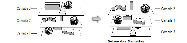
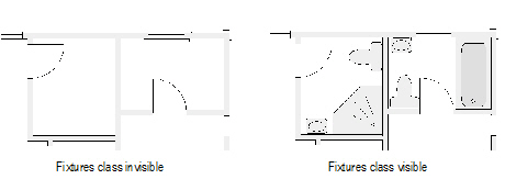
For example, for a drawing of a house with four separate plan layers
(first floor, second floor, basement, and roof), assign all bathroom fixtures
to a class called “Fixtures.” Make the Fixtures class invisible to print
the floor plans without fixtures, and then make them visible to print
the bathroom fixtures for each story of the house.
Class information can be linked to worksheets. Using the house example
in the previous paragraph, not only can the plumbing fixtures plan for
the house be printed, but a running inventory of the cost for all plumbing
fixtures can be kept (see “Using Worksheets”
on page 1315).
If Vectorworks Design Series is installed, you can set up the drawing
file to have a set of standard classes, which can be automatically assigned
to specific types of objects as they are created. See “Design
Series Layers, Classes, and Viewport Standards” na página 178.
~~~~~~~~~~~~~~~~~~~~~~~~~
Creating
Classes
Atribuindo
Objetos para Classes e Camadas
Exibindo
Classes em Ordem Hierárquica
Setting
Class Properties
Setting
the Active Class
Copying
and Pasting Classed Objects
Setting
Class and Design Layer Options
Setting
Visibilities in the Organization Dialog Box
The Visibility
Tool
Creating Classes
Decide on a naming scheme before you create classes. If there are a
large number of classes, organize them by naming each class with a compound
name consisting of up to four parts, separated by a dash. Each name part
represents a different level in the class naming structure. For example,
a drawing of a building might have a class structure that includes main
groups for architecture, plumbing, and electrical objects. Within the
architecture group, there might be door, floor, and wall groups. Those
groups in turn have subgroups—for example, the wall subgroup might have
interior and exterior designations. A class is named according to its
position in the class structure, as in Arch-Wall-Ext, Elec-Lite-Ceiling,
or Plum-Equip-New.
Class names impact hierarchical display on pop-up menus (including in
the Object Info palette, the View bar, and dialog boxes) and in the Organization
dialog box and (for Vectorworks Design Series products) the Navigation
palette. To enable or disable hierarchical display on pop-up menus, see
“Aba Seção” na página 50; for the
Organization dialog box and Navigation palette, see “Exibindo
Classes em Ordem Hierárquica” na página 154.
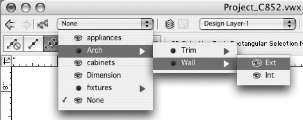
In the classes list on the View bar with hierarchical display enabled,
each main group is a menu option, with submenus for the subgroups. In
the following example, the Arch option has a Wall submenu, with Ext and
Int options. This type of organization makes it easy to assign classes
as objects are created.
Classes can be created as new, or imported from other current version
Vectorworks files or standard files.

To create a new class:
1. For convenience, a new class
can be added from multiple locations in the Vectorworks software.
• New button on the Classes tab of the Organization
dialog box (Tools > Organization)
• Classes button on the View bar to open the
Organization dialog box
• New Class option from the Classes drop-down
list on the View bar
• Class field on the Shape tab of the Object
Info palette
• New context menu on the Classes tab of the
Navigation palette (Vectorworks Design Series required)
2. From the New Class dialog box, create a new class,
or import a class and its properties from standard or existing Vectorworks
files.
Class Type |
Action |
Create New Class |
Creates a class based on current Attributes
palette settings; enter a class Name |
Import Classes |
Imports classes and their attributes from
standard files or existing files. Files located in the Standards
folder, as well as existing files selected previously, are displayed
in the list. Select a file; the available classes and descriptions
are listed beneath the file name.
Select the desired class(es). To select
multiple classes from the import list, hold the Ctrl (Windows)
or Command (Mac) key while you click. |
Show only classes
that are not in the current document |
If a class name in the current file matches
a class in the import file, normally that class is not included
on the list as an import option. To display all the classes to
be imported, deselect this option. The existing classes in the
file are replaced by any imported classes with the same name,
changing the existing class definitions (and any associated objects)
to those of the imported classes. |
Choose |
Click Choose
to select a file for class import. Files must be in the current
version. |
Creation Options |
|
Saved View Visibility |
Sets the visibility of the new class in
saved views (when saved views exist in the drawing) |
Viewport Visibility |
Sets the visibility of the new class in
viewports (when viewports exist in the drawing) |
Edit Properties After
Creation |
Immediately after creation, opens the
Edit Class(es) dialog box to set the properties of the new class(es) |
3. Click OK to create
the new class(es).
The classes display in the Classes list on the Organization
dialog box, View bar, Object Info palette, and (for Vectorworks Design
Series) the Navigation palette. When a new class is created, it does not
automatically become the active class.
~~~~~~~~~~~~~~~~~~~~~~~~~
Classes
Atribuindo
Objetos para Classes e Camadas
Importando
Estrutura de Desenho a partir de Standards ou Outros Arquivos
Exibindo
Classes em Ordem Hierárquica
Setting
Class Properties
Setting Class Properties
Once created, the classes display on the Classes tab of the Organization
dialog box, where various properties can be set and edited.

To edit classes:
1. Select Tools
> Organization. Alternatively, click the Classes
button on the View bar.
The Organization dialog box opens.
2. Select the Classes tab.
A list of the current classes in the drawing displays.
Depending on which view option is selected at the top of the dialog box,
either details or visibilities of the classes display. The visibility
of classes in the drawing area and the active class can be changed in
Details view. The visibility of classes
in viewports and in saved views can be changed in Visibilities view
(see “Setting Visibilities in the Organization
Dialog Box” na página 188).
3. To change other class properties, select one
or more classes and click Edit to open the
Edit Class(es) dialog box.
Click to
show/hide the parameters.
4. Click OK to
return to the Organization dialog box. If objects in an edited class already
exist in the drawing, and the class is set to use attributes “at creation,”
you are prompted to specify how to apply the changes to the existing objects.
5. Click OK from the
Organization dialog box to save the changes.
If multiple classes are simultaneously selected for editing, and some
or all of the attribute values are different for the selected classes,
the editing fields for those values indicate that the value is unknown.
When the OK button is clicked, the currently
defined settings shown are applied to all of the selected classes. Any
information with an unknown setting is not applied.
~~~~~~~~~~~~~~~~~~~~~~~~~
Exibindo
Classes em Ordem Hierárquica
Setting
Class Attributes
A Paleta
de Atributos
Resource
Libraries
Setting Class Attributes
There are two categories of attributes available for each object: object
attributes and class attributes. Object attributes are assigned directly
to an object from the Attributes palette, Object Info palette, or Resource
Browser (depending on the type of attribute). Class attributes are determined
by the object’s class settings.
The attributes that an object uses when it is created are controlled
by options in the Edit Class(es) dialog box:
• Use at Creation (for 2D graphic attributes)
• Use Text Style at Creation (for text in text
objects, callouts, dimensions, and notes)
• Use Textures/Surface Hatches at Creation (for
textures in walls, roofs, and other 3D shapes)
When one of these “use at creation” options is selected for a class,
objects created in that class or subsequently assigned to that class use
the class attributes. The Attributes palette displays an arrow to indicate
that the attributes have been set by class. If objects in that class already
existed before the “use at creation” option is selected, you are prompted
to decide how to apply the attributes to the existing objects.
Class attributes can also be assigned after objects are created:
• From
the Attributes palette, select Class Style or Class Thickness from the
appropriate attribute list.
• In
the Shape tab of the Object Info palette, select Class Text Style from
the Text Style list.
• In
the Render tab of the Object Info palette, select Class Texture from the
Texture list.
To override class attributes, select the object(s) and apply different
attributes directly from the Attributes palette, Object Info palette,
or Resource Browser.
Several plug-in objects (such as Vectorworks Design Series doors and
windows) offer the option to control the appearance and visibility of
the smaller object parts either individually, or by the same class as
the overall object. For example, select the <Door Class> option
to assign the door jamb, lintel, and threshold to the same class as the
door object. If you change the door’s class later, the appearance and
visibility of the smaller door parts automatically change according to
the new class.

For more information, see “A Paleta de
Atributos” na página 1091.
Setting the Active Class
To be able to remove or edit objects in a particular class, either the
class must be active or the class options must be set to allow modifications
to other classes (see “Setting Class and
Design Layer Options” na página 188). There are several ways
to change the active class.
If there are a small number of classes, switch between
classes with the Switch active layer/class shortcut
key combination specified in the Vectorworks preferences (see “Aba Edição” na página 47). This
selects a class by moving up or down through the class list one layer
at a time. If the drawing has a large number of classes, use one of the
following options.
Setting the Active Class in the Organization Dialog Box
To set the active class:
1. From the Organization dialog
box, select the Classes tab in Details view.
The active class is indicated by a check mark to the
left of the Class Name. The name of the class
also is highlighted in bold text.
2. To make a different class active, click the column
to the left of its name.
3. Click OK.
The dialog box closes and the active class displays.
Setting the Active Class
in the View Bar
To set the active class:
1. Click the Classes list on
the View bar to display a list of all of the drawing’s classes.
On Mac, the active class is indicated by a check mark;
on Windows, the class name is highlighted in bold text.
2. Click the class to be activated.
The classes list closes and the active class displays.
 Setting the Active Class
in the Navigation Palette
Setting the Active Class
in the Navigation Palette
To set the active class:
1. From the Navigation palette,
select the Classes tab.
The active class is indicated by a check mark to the
left of the class name. The name of the class also is highlighted in bold
text.
2. To make a different class active, click the column
to the left of its name.
Alternatively, Right-click (Windows) or Ctrl-click (Mac)
on the class to be activated and select Activate from
the context menu.
Setting the Active Class
in the Document Context Menu
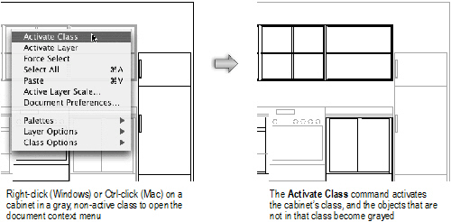
If multiple classes are set to be visible, and the class options are
set to show those other classes, the drawing area may display objects
that are in non-active classes. Use the Activate
Class command to make the class of one of these objects active.
The Force Select command
on the document context menu also changes the active class and the active
layer (if necessary), and selects the clicked object.
To set the active class:
1. In the drawing area, right-click
(Windows) or Ctrl-click (Mac) a visible object in a non-active class.
2. From the document context menu, select Activate Class.
The object’s class becomes active.
Copying and Pasting Classed
Objects
Objects in a class can be copied and pasted from one drawing to another,
even if the destination drawing does not contain the same class as the
original drawing. The program automatically creates a new class in the
destination drawing and transfers all of the class information from the
source drawing. If the destination drawing already has a class with the
same name as the source drawing, only the object information is pasted.
All of the class information for the destination drawing’s class remains
unchanged.
When you paste objects that could become invisible due to class visibility
settings, specify whether the invisible classes should be made visible
so that the pasted objects can be seen.
 Design
Series Layers, Classes, and Viewport Standards
Design
Series Layers, Classes, and Viewport Standards
The standards for the Vectorworks Architect and Landmark products take
advantage of layer and class characteristics.
Class Characteristics
Each drawing object is assigned to a class, as well as a layer. The
class determines the object’s appearance, while the layer determines the
object’s location. Classes apply to the entire file and control the visibility
of objects. The currently active class is visible; but classes can be
set to be visible, invisible, or grayed when they are inactive. Complex
objects, such as symbols or plug-in objects, may contain more than one
class; if so, different parts of the object can be hidden or shown. Classes
can also be used to assign graphical attributes, textures, and text styles
to objects.
Many plug-in objects that are included with Vectorworks Architect and
Landmark products are set with pre-assigned classes. The appropriate classes
are created at setup and by certain other commands (see “Automatically
Created Classes” na página 179). The use of automatic classing
is determined with the Standard Naming setup
command. For more information, see “Importando
Estrutura de Desenho a partir de Standards ou Outros Arquivos” na página 156 and
“Classes” na página 171.
Layer and Viewport Characteristics
A layer is a named container that holds items. There are two types of
layers: design layers and sheet layers. Design layers are used for drawing
and modeling the elements of a project. Sheet layers are created for the
presentation of a finalized project, and can contain viewports, title
blocks, notes, and other annotations. A viewport, located on a sheet or
design layer, is a particular combination of visible, grayed, and/or hidden
design layers and classes.
Layers have certain characteristics that are used when drawing and structuring
files:
• Design
layers can automatically set default elevation values for objects they
contain. They create natural structural divisions within a project for
objects on different floors or different vertical locations within a floor.
• Design
layers can be visible, invisible, or grayed. Sheet layers are always set
to Active Only.
• Design
layers, as well as viewports, can be displayed at different drawing scales,
for the display of all aspects of a project plan from the site model to
details.
• Design
layers, as well as viewports, can have different 3D views. A building
can be viewed in Plan view in one viewport and in an elevation or perspective
view in another.
• Layers
can be contained in different files and shared using workgroup referencing.
Projects set up according to standards contain both design layers and
sheet layers with viewports. An architectural project file contains, at
a minimum, stories with design layers for every level, as well as a number
of viewports on sheet layers.
A typical Vectorworks Landmark product standard file setup includes
landscape site plans composed of shared model information on four layers:
• Mod-Site-Arch
– contains any buildings or other improvements
• Mod-Site-Civil
– contains topographic and survey information
• Mod-Site-DTMData
– contains the site model output
• Mod-Site-Landscape
– contains tree and planting data
When a file is set up with the Create Standard
Viewports command, the appropriate classes and layers are
created automatically. The number and types of layers and classes created
depend on the setup selections. In the Vectorworks Architect product,
design layers are created by stories, and begin with “Mod-” (model layers,
since this is where the model is designed). The Create
Standard Viewports command creates the appropriate viewports
and sheet layers for the viewports (beginning with “Sheet-”), along with
the appropriate classes if they are not already in the file (see “Standard Viewports” na página 180).
The Standard Naming command establishes
or changes the naming conventions used for these classes, design layers,
sheet layers, and viewports or saved views (see “Standard
Naming” na página 88).
Set up a new, blank file with standards, and then
save as a template for future use.
Setup standards are determined by the LayerMap.G
worksheet, which can be imported and customized by advanced users. If
an existing file already contains a set of custom standards and the LayerMap.G
worksheet is present in the file, the Import LayerMap.G dialog box opens
when selecting Create Standard Viewports.
Select whether to keep the imported and customized worksheet, or whether
to revert to the standard setup. See “Using
the Layermap Worksheet” on page 1884 for more information.
~~~~~~~~~~~~~~~~~~~~~~~~~
Automatically
Created Classes
Standard
Viewports
 Automatically
Created Classes
Automatically
Created Classes
Several classes are created automatically by features in the Vectorworks
Architect and Landmark products, regardless of whether standards have
been established at setup. See “Setting
Class Properties” na página 173.
• NonPlot
(Vectorworks Architect): This class is created as part of doors and windows.
The loci that define the window and door edges are created in this class,
which is normally set to Invisible so that the loci are hidden.
• Redlines
(Vectorworks Architect, Landmark, Spotlight): This class is created by
the Redline tool. All redline objects
are placed in this class, which allows all redlines in the file to be
shown or hidden. This class is toggled to visible and invisible by the
Show or Hide Redlines command.
• Guides
(Vectorworks Architect and Landmark): This class is created and used by
selecting Modify >
Guides > Make Guide.
• The
Wall Framer command (Vectorworks Architect)
creates the following classes: Framer-Block, Framer-Sole Plate, Framer-Header,
Framer-Stud, Framer-Sill, and Framer-Top Plate.
• Site-DTM-Modifier
(Vectorworks Architect and Landmark): This class is created by the Pad,
Texture Bed, Grade Limits, and Spoil Pile objects. The Landscape Walls
and Roadway objects include pad and grade limit objects if the Use
Site Modifiers and Use Grade Limits
check box is selected on the Object Info palette. This class is
toggled to visible and invisible by the Show or
Hide Site Modifiers command.
• Irrigation-SprayPat
(Vectorworks Landmark): This class is created by using the Irrigation
Head and Drip Emitter objects. This class is toggled to visible and invisible
by the Show or Hide Spray Pattern command.
Object Auto-classing
Auto-classing is the automatic assignment of certain objects to
a default class. Many plug-in objects in the libraries provided have been
pre-assigned to the proper class according to the drawing standard for
the Vectorworks Architect and Landmark products (VWArch). For a list of
auto-classing objects, see “Object Auto-classing”
na página 179.
If the Use Auto-classing check box
is selected in Standard Naming (see “Standard
Naming” na página 88), then these plug-in objects will be automatically
placed in the designated class as they are added to the drawing. The object’s
class is created automatically if it does not yet exist.
If a file has not been structured according to setup standards, or the
Use Auto-classing check box is not selected,
the objects are placed in the active class. The objects, upon regeneration,
are assigned to the proper class if the file is later set up. Any symbol,
when created, can be set to default to a class from the Symbol Insertion
Options dialog box.
If you use a naming standard other than VWArch, the default class of
the object libraries must be reset.
Save a backup version of the object libraries before
editing them. See “Resource Libraries”
na página 215.
To set the default class of all the symbols in a library file:
1. Select File
> Open.
The standard Open dialog box opens.
2. Select the Libraries folder, and then click Open.
3. Select the first object library file to convert,
and then click Open.
The selected file opens in the drawing window.
4. Select Tools > Utilities
> Set Default Symbol Class.
A warning dialog box opens. Click Yes
to acknowledge converting all symbol definitions in the file to
the new default class name.
The Enter String dialog box opens.
5. Enter the default class name for the symbols,
and then click OK.
Ensure that the name is spelled correctly to match
the desired custom class standard. This command can be undone if necessary.
If the name matches an existing name in the file other than a class, an
alert dialog box opens.
6. Select File > Save to
save the changes.
7. Repeat steps 1 through 6 for each object library.
Any time that symbols are used from this file, they
will take on the specified class as their default class.
The command does not distinguish between one symbol
definition and another. All symbol definitions in the file will take on
the new class name. For that reason, to use on custom libraries, run the
command on a copy of the file.
~~~~~~~~~~~~~~~~~~~~~~~~~
Auto-classing
Objects
 Standard
Viewports
Standard
Viewports
Viewports are created on sheet layers, and display a specific portion
of a drawing with a combination of visible, grayed, and/or hidden design
layers and classes. Viewports can be cropped, rotated, and annotated,
and the sheet layer print settings can be saved. Several viewports can
be included on one sheet layer. For the Vectorworks Architect and Landmark
products, the Create Standard Viewports command
creates standards-compliant viewports and their associated sheet layers,
with the layer and class visibilities of a standard drawing. See “Creating Sheet Layer Viewports” na página 1612.
If desired, views corresponding to the viewports can also be created.
This allows easy navigation through the different drawing views (with
set layer and class visibilities) during the design process.
Viewports are created in five categories. The available viewport types
are:
• Site
Plan Drawings
• Project
Plan Drawings
• Floor
Plan Drawings
• Auxiliary
Plan Drawings
• Notation
Drawings
Select the Create Standard Viewports command
again to make changes to the project settings at any time. The column
on the right shows the current viewports when the command is run again.
~~~~~~~~~~~~~~~~~~~~~~~~~
Setting
Standard Viewport Preferences
Creating
Standard Viewports
 Setting
Standard Viewport Preferences
Setting
Standard Viewport Preferences
Stories must be created before creating standard viewports (see “Setting Up the Building Structure with
Stories” na página 166). The default viewport scale and sheet
border settings can be set prior to adding standard viewports to a project.
To set viewport preferences:
1. Select File
> Document Settings > Create Standard Viewports.
The Create Standard Viewports dialog box opens.
2. Click Preferences.
The Create Viewport Preferences dialog box opens. The
preferences apply as viewports are added to the list for inclusion in
the project.
3. Set the default scale for each type of viewport
and select a sheet border and, if desired, title block to add automatically
to each sheet layer. The scale settings affect only the viewport scale,
not the layer scale of any model layers. See “Adding
a Sheet Border” na página 74 for more information on sheet borders.
4. Click OK to return
to the Create Standard Viewports dialog box.
~~~~~~~~~~~~~~~~~~~~~~~~~
Creating
Standard Viewports
Standard
Viewports
 Creating
Standard Viewports
Creating
Standard Viewports
Stories must be created before creating standard viewports (see “Setting Up the Building Structure with
Stories” na página 166). To create standard viewports:
1. Select File
> Document Settings > Create Standard Viewports.
The Create Standard Viewports dialog box opens. Select
a drawing category from the Type of Drawing list.
The available drawing types display in the Drawing
Types list on the left, with a short description beneath.
Select the viewport to be created in the Drawing
Types list and then click Add to
move it to the Viewports to Be Created list
on the right.
For auxiliary view viewports (sections and elevations),
types with a -Man suffix (such as Sections-Man) typically indicate that
the elements of the section or elevation are to be drawn manually on,
for instance, Mod-Section or Mod-Elevation layers, which are created along
with the viewports. The visibility of all other layers is set to Invisible
for these viewports. Types with a -VP suffix (such as Sections-VP) are
for creating a view or a section viewport of the model from existing Mod-
layers. No new layers are created and the visibility of all existing Mod-
layers is set to Visible for these viewports.
Click to
show/hide the parameters.
2. Once the list of viewports is ready, click OK. Any sheet layers specified that do not
already exist in the drawing are created along with the listed viewports
(and views if the Create Corresponding View
option was selected).
In a new drawing, the viewports display with a red X,
indicating that they are currently empty. As the drawing is developed
on the design layers, the viewports will display the contents appropriately.
Depending on the rendering mode specified, some viewports may require
updating with the Update Selected Viewports
command.
~~~~~~~~~~~~~~~~~~~~~~~~~
Standard
Viewports
Standard
Naming
 Sheet
List Indexing
Sheet
List Indexing
The Create Sheet List command compiles
the current sheet border information for use as a sheet list index or
worksheet.
To create a sheet list index:
1. Select Tools
> Reports > Create Sheet
List.
The Create Sheet List dialog box opens.
Click to
show/hide the parameters.
2. Move the desired title block entries to the proposed
sheet list to create the sheet list, and format the list by clicking Format; select whether to create a text object
or worksheet from the list.
3. Click OK.
4. If the sheet list index is formatted as a text
block, click to select the top left and bottom right corners of the sheet
list area; the text wraps to fit within this width. If the sheet list
index is formatted as a worksheet, click to add the worksheet to the file.
The sheet list index worksheet can also be added to
the drawing from the VA Create Schedule command
or the Resource Browser. From the Resource Browser, open the default architectural
reports file from the [Vectorworks]\Libraries folder that is included
with the Vectorworks Architect product (see “Resource
Libraries” na página 215). Drag the Sheet List worksheet to the
drawing. The worksheet is populated with information from the objects
in the current drawing.
Saved
Views
A saved view is like a camera that is set up to show a drawing from
a certain orientation, with a specific set of viewing parameters, including
which class and design layer are active, the visibilities of the inactive
classes and the design layers, the current zoom and pan, and the page
location. If Vectorworks Design Series is installed, the plan rotation
and the clip cube position can be saved.
Views are also used to create Move Along Path animations (see “Criando e Editando Animações Mover ao Longo
do Caminho” on page 1177 for more information).
Saved views can be created, edited, duplicated, and deleted from the
Organization dialog box as described in the following sections.
Click
here for a video tip on this topic (Internet connection required).
~~~~~~~~~~~~~~~~~~~~~~~~~
Creating
Saved Views
Editing
Saved Views
Creating
or Editing Saved Views Using the Saved Views Menu
Viewing
History
Organizando
o Desenho
Creating Saved Views
To save the current drawing area view:
1. Select View
> Save View.
Alternatively, from the Organization dialog box, click
the Saved Views tab, and then click the New button.
If Vectorworks Design Series is installed, from the Navigation palette,
click the Saved Views tab, and then select the New
command from the navigation menu.
2. The Save View dialog box opens.
3. Specify the view options, the active layer and
class, and the visibilities of layers and classes.
Click to
show/hide the parameters.
4. Click OK to
save the view with the specified settings. The saved view is then available
from the Saved Views menu and from the
Organization dialog box.
~~~~~~~~~~~~~~~~~~~~~~~~~
Editing
Saved Views
Creating
or Editing Saved Views Using the Saved Views Menu
Viewing
History
Setting
Class and Design Layer Options
Setting
Visibilities in the Organization Dialog Box
Editing Saved Views
Set the active class and layer, the class and design layer options,
and the class and design layer visibilities when you create the saved
view (in the Save View dialog box). Those initial settings can be changed
later from the Organization dialog box.
To edit a saved view:
1. Select Tools
> Organization. The Organization dialog box opens.
2. Select the Saved Views tab in Visibilities
view.
The visibilities of classes and design layers for the
selected saved view display.
3. Select a view to edit from the Saved
View Name list.
4. If Save Class Visibility was
selected in the Save View dialog box, Class Options and
Active Class are enabled in the Organization
dialog box. If Save Layer Visibility was
selected in the Save View dialog box, Layer Options and
Active Layer are enabled in the Organization
dialog box. Change the Active Layer and
the Active Class as necessary. Change the
Class Options and Layer
Options as described in “Setting
Class and Design Layer Options” na página 188.
5. Change the visibilities of classes and design
layers as necessary. See “Setting Visibilities
in the Organization Dialog Box” na página 188.
6. To change other saved view properties, click
Edit.
The Edit Saved View dialog box opens.
The settings are the same as when the view is created.
Classes and layers that were added after a view was created are listed
as visible in the visibility settings.
If the layer or class visibility was saved when the
view was created, Restore Layer Visibility and
Restore Class Visibility are enabled.
Select Restore Layer Visibility to restore
the layer visibilities, the layer options, and the active layer that were
set when the view was saved. Select Restore Class
Visibility to restore the class visibilities, the class options,
and the active class that were set when the view was saved.
Saved views are saved as VectorScript macros. If necessary,
click Edit Script to edit the script.
7. Click OK to
save the changes. Click OK again to close
the Organization dialog box.
Another way to edit a saved view is through the Saved Views palette.
Select Window > Script Palettes > Saved
Views. Press the Option (Mac) or Alt (Windows) key and double-click
the view name to edit. Double-click the view script name to switch the
current drawing area to the saved view.
If Vectorworks Design Series is installed, you can also edit saved views
from the Navigation palette; see “The Navigation
Palette” na página 194.
~~~~~~~~~~~~~~~~~~~~~~~~~
Creating
Saved Views
Creating
or Editing Saved Views Using the Saved Views Menu
 Redefining
Saved Views
Redefining
Saved Views
To change the content of a saved view, use the Redefine command.
This changes the saved view settings to match those of the current drawing
area view, including the current layer options and class options, the
plan rotation, the visibility of layers and classes that are inactive,
and the active layer and class.
To redefine a saved view:
1. From the Navigation palette,
select the Saved Views tab.
2. Select the view to be changed from the list.
3. From the Navigation menu or the view context
menu, select Redefine.
The Redefine Saved View dialog box opens. Specify the
view options and the visibility parameters.
Click to
show/hide the parameters.
4. Click OK to save
the current drawing area view with the specified settings.
Creating or Editing Saved Views
Using the Saved Views Menu
The View bar has shortcuts to save a view, to edit a saved view,
or to switch the current drawing area view to a previously saved view.
Views can also be accessed through the Saved Views palette.
Select Window > Script Palettes > Saved
Views. Double-click the view name to switch to that view.
To use the Saved Views menu:
1. Click the Saved
Views menu on the View bar.

2. Select the desired item from the menu.
Menu Item |
Description |
Save View |
Opens the Save View dialog box |
Edit View |
Opens the Saved Views tab of the Organization
dialog box |
List of saved views |
Select a saved view from the list to switch
to that view |
~~~~~~~~~~~~~~~~~~~~~~~~~
Creating
Saved Views
Editing
Saved Views
Viewing
History
Setting
Class and Design Layer Options
The Class Options and Layer
Options commands control how all the classes or design layers
in a drawing display. For example, a drawing project can be set to display
only the active class, temporarily hiding all objects assigned to other
classes.
To change the options for displaying, snapping to, and editing objects
in the current class or design layer:
1. Select View
> Class Options (or Layer Options)
and then the option.
Alternatively, right-click (Windows) or Ctrl-click (Mac)
in the drawing area and select Class Options or
Layer Options from the document context menu.
Command |
Description |
Active
Only |
Displays only objects in the active class/layer;
only the active class/layer prints |
Gray
Others |
Displays the active class/layer normally
and all other classes/layers appear dimmed (except for those set
to invisible); even though visible, objects in dimmed classes/layers
cannot be edited |
Gray/Snap Others |
Displays the active class/layer normally
and all other classes/layers appear dimmed (except for those set
to invisible); objects in any normally displayed or gray class/layer
can be snapped to. Only objects in the active class/layer can
be edited. |
Show
Others |
All classes/layers display normally, except
for those set to invisible or grayed; even though visible, objects
in classes/layers other than the active class/layer are not editable
and cannot be snapped to |
Show/Snap Others |
All classes/layers display normally, except
for those set to invisible or grayed; objects in any normally
displayed or gray class/layer can be snapped to. Only objects
in the active class/layer can be edited. |
Show/Snap/Modify
Others |
All classes/layers display normally, except
for those set to invisible or grayed. Objects in any normally
displayed or gray class/layer can be snapped to; only objects
in normally displayed classes/layers can be edited. (An object
on another layer can only be edited if its layer scale and view
are the same as those of the active layer.) Locked objects display
with gray highlighting. |
2. The current class or design layer display changes
accordingly.
Click
here for a video tip on this topic (Internet access required).
~~~~~~~~~~~~~~~~~~~~~~~~~
Setting
Visibilities in the Organization Dialog Box
The Visibility
Tool
Setting
Visibilities in the Organization Dialog Box
The active class and design layer are always visible. Each inactive
class and design layer can be set to be visible, invisible, or gray. These
visibilities can be set independently for the drawing area, saved views,
and viewports.
The level of gray for grayed layers and classes can
be adjusted for printing; see “Imprimindo
um Arquivo” na página 1755.
Using Visibility Columns
For maximum usability, class and design layer visibilities can be set
in multiple places in the Organization dialog box, and also in other dialog
boxes. The Visibility columns work the same
wherever they are used.
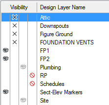
To change the setting for a single class or design layer, click in one
of its visibility columns. To change the settings for multiple items,
click a visibility column as follows:
• Press
the Ctrl key (Windows) or Cmd key (Mac) and click selected class or layer
rows
• Press
the Shift key and click the first and last rows of a group of classes
or layers
• Press
the Alt key (Windows) or Option key (Mac) and click any row to change
all classes or layers
For classes displayed in hierarchical order, change
the visibility setting of a group header to change the visibility of all
of its subclasses; see “Exibindo Classes
em Ordem Hierárquica” na página 154.
Column |
Description |
Visible

|
Class/design layer is visible; objects
in this class/layer display when another class/layer is active |
Invisible

|
Class/design layer is invisible; objects
in this class/layer display only when the class/layer is active |
Gray

|
Class/design layer is gray; objects in
this class/layer are dimmed when another class/layer is active |
Don’t Save

|
For saved views, a fourth column displays
to the right of the other columns. When selected, class/design
layer visibility is not saved for the saved view; the current
class/layer visibility is used when the view is displayed. |
Setting Class and Design
Layer Visibility for the Drawing Area
Use the Organization dialog box to set the visibilities of classes and
design layers in the drawing area. If Vectorworks Design Series software
is installed, you can use the Navigation palette to set visibilities also
(see “The Navigation Palette” na página 194).
Class and design layer visibility in the drawing area are also affected
by the Class Options and Layer
Options settings. See “Setting
Class and Design Layer Options” na página 188 for details.
To set the class and design layer visibilities for the drawing area:
1. From the Organization dialog
box, select the Classes or Design Layers tab in Details
view.
2. Change the Visibility
settings as desired.
3. To see the changes before saving them, click
Preview.
4. Click OK to save
the changes.
Setting Class and Design
Layer Visibility for Viewports and Saved Views
Use the Organization dialog box to set the visibilities of classes and
design layers in existing viewports and saved views. You can also set
these visibilities while creating and editing classes, design layers,
viewports, and saved views, as described in the following topics:
• “Creating Classes” na página 172 and
“Setting Class Properties” na página 173
• “Criando Camadas” na página 157 and
“Definindo Propriedades da Camada de Projeto”
na página 160
• “Viewport Properties” na página 1632
• “Creating Saved Views” na página 184
To set the class and design layer visibilities for viewports and saved
views:
1. From the Organization dialog
box, select a tab in Visibilities view.
Organization Dialog Box
Tab |
Sets
Visibility of |
Classes |
Classes in viewports and saved views;
if classes are displayed in hierarchical order and a class group
header is selected, the viewport and saved view lists are disabled |
Design Layer |
Design layers in viewports and saved views |
Viewports |
Classes and design layers in a viewport |
Saved Views |
Classes and design layers in a saved view |
2. Select one or more class, design layer, viewport,
or saved view names and change the Visibility settings
for classes and design layers as desired.
3. On the Saved Views tab, change the active design
layer and class, and the design layer and class options.
4. To see the changes before saving them, click
Preview (not available on the Saved Views
tab).
5. Click OK to save
the changes.
Click
here for a video tip about this topic (Internet access required).
~~~~~~~~~~~~~~~~~~~~~~~~~
Setting
Class and Design Layer Options
The Visibility
Tool
The
Visibility Tool
The Visibility tool changes the visibility
of either the layer or class associated with a clicked object. If you
click an object in the drawing area, the document visibility changes.
If you click an object in a sheet layer or design layer viewport, only
the visibility in that viewport changes (with some exceptions). You can
also make rapid changes to the visibilities of multiple layers or classes
in the drawing at one time by double-clicking the tool itself.
You cannot change the class and layer visibilities within
a section viewport with the Visibility tool.
The Visibility tool is available in
the workspaces of all Vectorworks Design Series products; for the Vectorworks
Fundamentals product, you can edit the workspace to add the Visibility
tool.
Several modes are available, to specify whether to change class or layer
visibility, and what type of visibility change to make.

Mode |
Description |
Classes |
Affects the visibility of the clicked
object’s class |
Layers |
Affects the visibility of the clicked
object’s layer |
Visible |
Sets the clicked object’s class or layer
to visible |
Invisible |
Hides the clicked object’s class or layer |
Greyed |
Sets the clicked object’s class or layer
to gray |
Preferences |
Specifies the behavior when the Visibility tool is double-clicked |
Click
here for a video tip about this topic (Internet access required).
Layer or Class Visibility Changes

To change class or layer visibilities based on a clicked
object:
1. Click the Visibility
tool from the Basic palette.
2. From the Tool bar, select Classes
or Layers mode. Then select whether
to make the object’s class or layer Visible,
Invisible, or Greyed.
3. If the class or layer to be changed is currently
invisible, ensure that the class or layer options are not set to Active
Only. Press and hold the shortcut key for the Visibility tool
(V by default) to temporarily make all classes (in Classes mode) or layers
(in Layers mode) visible. If the cursor is over a viewport, all classes
or layers in the viewport become visible.
In Classes mode, if the cursor is over a design layer
viewport that is set to use the class visibilities of the document, all
document classes become visible (which includes the classes in the viewport).
4. Move the cursor over a drawing object that is
in the class or layer to be changed. All objects that will be affected
by the visibility change are highlighted. In addition, a screen tip indicates
the name of the class or layer that will be changed, as well as its current
visibility setting. If the object is in a viewport, the screen tip also
indicates the name of the viewport in which the change will be made.
In Classes mode, if the object is in a design layer
viewport that is set to use the class visibilities of the document, the
screen tip does not show the viewport name. This indicates that a click
on the object will change the class visibility for the document (not the
viewport)—including objects of that class that are not in the viewport.
5. Click on the object to change the visibility
setting for its class or layer.
The object’s class or layer is set to visible, invisible,
or gray, and the Message bar shows the change that occurred. The Navigation
palette (Vectorworks Design Series required) updates to display the new
visibility status. On a design layer, changes to class visibility redraw
the entire drawing; changes to layer visibility redraw the layer.
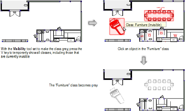
Reasons for Class or Layer Visibility not Changing
When you use the Visibility tool to
make class or layer changes, several factors may prevent the visibility
from changing as expected.
• The
layer and class options control the visibility of objects in the inactive
layers and classes. For example, if the layer options are set to gray
objects in inactive layers, grayed objects do not become fully visible
when clicked with the Visibility tool.
(See “Setting Class and Design Layer Options”
na página 188.) An alert displays in this situation.
• The
Visibility tool cannot hide or gray
the active class or layer immediately, since the active class or layer
is always set to visible. An alert displays in this situation.
• A
container object (such as a symbol or a group) and its component parts
can belong to different classes, and their visibilities can be set differently.
For example, if the classes of the individual objects that make up a symbol
are set to invisible or gray, they do not become visible when the symbol’s
class is made visible.
• In
a viewport, changes to class or layer visibility display immediately if
the viewport has a background render mode of Wireframe, Sketch, or OpenGL.
For other render modes, you must update the viewport to see the visibility
change. An alert displays in this situation.
• If
a design layer viewport is embedded in another viewport, several factors
affect the behavior of the Visibility tool.
See “Visibility Tool Behavior in Embedded
Viewports” na página 193 for more information.
Global Visibility Changes
The Visibility tool can make global
changes to the class or layer visibilities of a drawing. In a complex
drawing, for example, this can be an easy way to quickly show only the
classes or layers of selected objects. All classes or layers can easily
be set to show again. This feature does not affect visibilities in viewports.

To make global changes to the visibility of classes
or layers:
1. To make changes to the class
or layer visibility of selected objects, select the objects first.
The objects do not need to be in the same class or
layer.
2. Click the Visibility
tool from the Basic palette.
3. Select Preferences from
the Tool bar.
The Visibility Tool Preferences dialog box opens. Specify
the effect to occur when the Visibility tool
is double-clicked.
Click to
show/hide the parameters.
4. Click OK.
5. Double-click the Visibility
tool to execute the selected action.
The classes or layers in the drawing area are set to
visible or invisible as specified, and the Message bar shows the change
that occurred. The Navigation palette (Vectorworks Design Series required)
updates to display the new visibility status.
Reasons for Global Visibility not Changing
When you use the Visibility tool to
make global changes, several factors may prevent the visibility from changing
as expected.
• The
layer and class options control the visibility of objects in the inactive
layers and classes. For example, if the layer options are set to gray
objects in inactive layers, grayed objects do not become fully visible
when the Visibility tool is double-clicked.
(See “Setting Class and Design Layer Options”
na página 188.) An alert displays in this situation.
• The
Visibility tool cannot hide the active
class or layer immediately, since the active class or layer is always
set to visible. An alert displays in this situation.
• A
container object (such as a symbol or a group) and its component parts
can belong to different classes, and their visibilities can be set differently.
For example, if the classes of the individual objects that make up a symbol
are set to invisible or gray, they become visible only when the first
double-click option (Makes all classes visible) is used.
Visibility Tool Behavior in
Embedded Viewports
Design layer viewports can be embedded in both sheet layer and design
layer viewports, and they can be referenced or not. There are settings
in the viewport properties of all of these viewports to control the way
classes and layers display, which affect the behavior of the Visibility
tool.
Cases Where Viewport Visibility Does not Change
The following cases describe the conditions under which the Visibility tool
cannot change the visibilities of the class or layer of a clicked object,
when the object is in a design layer viewport that is embedded in another
viewport.
• The
top-level viewport is a sheet layer viewport, and it is set to use the
class or layer visibilities of the embedded viewport. The tool can only
change the top-level viewport’s visibility setting for the class or layer
of the embedded viewport itself. The tool cannot change the visibility
for the class or layer of an object inside the embedded viewport.
• The
top-level viewport is a sheet layer viewport, and it is not set to use
the class or layer visibilities of the embedded viewport. However, the
embedded viewport is referenced. In a referenced viewport, each class
can either keep its own settings, or take on the settings of the document
in which it is embedded. In Classes mode, if you click on an object whose
class is set to keep its own settings, the tool changes the top-level
viewport’s visibility setting for the class of the embedded viewport itself.
In Layers mode, the tool can only change the top-level viewport’s visibility
setting for the layer of the embedded viewport itself.
• The
top-level viewport is a design layer viewport, and the embedded viewport
is referenced. In Classes mode, if you click on an object whose class
is set to keep its own settings, the tool changes the top-level viewport’s
visibility setting for the class of the embedded viewport itself.
• The
top-level viewport is a design layer viewport. In Layers mode, the tool
can only change the top-level viewport’s visibility setting for the layer
of the embedded viewport itself. The tool cannot change the visibility
for the layer of an object inside the embedded viewport.
Cases Where Class Visibility for the Document Changes
The following cases describe the conditions under which the Visibility tool
changes the class visibilities for the entire document, when you click
on an object in a design layer viewport that is embedded in another viewport.
• The
top-level viewport is a design layer viewport, and it is set to use the
class visibilities of the document. The embedded viewport is not referenced.
The tool changes the visibility of the class of the clicked object, not
only in the viewport, but in the entire document.
• The
top-level viewport is a design layer viewport, and it is set to use the
class visibilities of the document. The embedded viewport is referenced.
If the clicked object belongs to a class that is set to take on the settings
of the document, the tool changes the class visibility for the entire
document.
~~~~~~~~~~~~~~~~~~~~~~~~~
Setting
Class and Design Layer Options
Changing
the Class Properties of Sheet Layer or Design Layer Viewports
 The
Navigation Palette
The
Navigation Palette
The Navigation palette provides access to classes, design layers, sheet
layers, viewports, and saved views, similar to the Organization dialog
box. However, unlike the Organization dialog box, the drawing area is
accessible while the Navigation palette is open.
To use the Navigation palette:
1. Select Window
> Palettes > Navigation.
The Navigation palette opens.

Click the desired tab to set the active tab upon opening
the Navigation palette. Select Window > Palettes
> Save Palette Positions to save the changes. To revert
the active tab back to the setting established when a custom workspace
was created (in the User Data and Preferences folder), click Reset
Saved Settings from the Session tab of Vectorworks preferences
(see “Aba Seção” na página 50).
2. Select the appropriate tab: Classes, Design Layers,
Sheet Layers, Viewports, Saved Views, or References.
A list of items of that type in the current drawing displays. If a description
was entered for a class or layer, the description displays in a screen
tip when you position the cursor over the item name; on Windows, click
the disclosure arrow on the screen tip to collapse or expand it.
3. Change the settings for classes, design layers,
sheet layers, viewports, saved views, or references as needed.
• Click
a class or design layer’s Visibility column
to set the visibility for objects in that layer. To set the same visibility
for all classes or design layers in the list, Option-click (Mac) or Alt-click
(Windows) one of the Visibility columns.
• Use
the navigation context menu options to toggle the display of classes in
hierarchical order, or to expand or collapse the class list for better
manageability.
• If
classes are displayed in hierarchical order, click the Visibility column
for a class group header and all of its sublevels inherit that visibility
setting.
• Double-click
a class, design layer, or sheet layer to activate it. Or, click the column
to the left of the item’s name to activate it.
• Double-click
a saved view to switch to that view.
• Double-click
a viewport to switch the active layer to the sheet layer or design layer
that contains the viewport, and to select the viewport (if a viewport
is in a class with settings that prevent the viewport from being selected,
a message displays to indicate that the active class changed to the viewport
class).
• Select
a class or design layer and then select one of the Class
Options or Layer Options.
• Change
the stacking order of a design layer or sheet layer by clicking the number
in its # column and dragging it up or
down the list.
• Double-click
on a tab in the Navigation palette to open the equivalent tab in the Organization
dialog box.
See the following sections for details:
• “Funcionalidade da Caixa de Listagem” na
página 41
• “Exibindo Classes em Ordem Hierárquica”
na página 154
• “Alterando a Ordem de Sobreposição da Camada
de Projeto” na página 162
• “Setting the Active Layer” na página 158
• “Changing the Sheet Layer Stacking Order”
na página 165
• “Creating Classes” na página 172
• “Setting the Active Class” na página 176
• “Saved Views” na página 183
• “Setting Visibilities in the Organization
Dialog Box” na página 188
4. The Navigation menu
provides creation and management functions. Select a list item and then
select the desired function from the Navigation
menu to the right of the References tab.
Alternatively, Ctrl-click (Mac) or right-click (Windows)
a list item and then select the desired function from the navigation context
menu.
Menu Command |
Function |
Classes tab |
|
New |
Select New to
open the New Class dialog box. See “Creating
Classes” na página 172.
When a new class is created, it does not automatically
become the active class. |
Edit |
Select a class and then select Edit to
edit it in the Edit Class(es) dialog box. See “Setting
Class Properties” na página 173. This option is not available
when classes are displayed in hierarchical order and a class group
header is selected. |
Duplicate |
Select a class and then select Duplicate to
create a copy of it. The name of the duplicate is the same as
the original class, with a number added (as in cabinets-2); if
the original name ends in a number, the next available sequential
number is used. This option is not available when classes are
displayed in hierarchical order and a class group header is selected.
|
Delete |
Select a class and then select Delete to
open the Delete Class(es) dialog box. Specify what to do with
the objects currently assigned to the class(es) being deleted
(delete them, or reassign them to another selected class). Click
OK to return to the Navigation
palette. The program moves all objects in the deleted class(es)
to the appropriate class, or deletes them, as specified. Shortcut
keys for this command are Delete (Windows) and Forward Delete
(Mac). This option is not available when classes are displayed
in hierarchical order and a class group header is selected.
The Dimension and None classes cannot be deleted.
These are default classes in every drawing. |
Assign to Selection |
Select one or more drawing object(s) and
one class; then select Assign to Selection to
place the object(s) in the specified class |
Activate |
Select a class and then select Activate to
make that class active for every design layer, viewport, and saved
view without class visibility saved. (Enter is a shortcut key
for this command.) |
Details |
Select Details to
open the Organization dialog box to the Classes tab in Details
view; double-clicking the Classes tab in the Navigation palette
is a shortcut for this command |
Visibilities |
Select a class and then select Visibilities to
open the Organization dialog box to the Classes tab in Visibilities
view (showing Viewport and Saved View visibilities for the class) |
Select All |
Choose Select All
to select all classes |
Hierarchical Display |
Toggles the hierarchical display of classes
on or off |
Expand All |
When classes are displayed in hierarchical
order, displays all classes in the file |
Collapse All |
When classes are displayed in hierarchical
order, collapses the list to display only top-level classes (those
with no dash in the name) and class group headers |
Design Layers tab |
|
New |
Select New
to open the New Design Layer dialog box.
When a new layer is created, it becomes the
active layer. |
Edit |
Select a layer and then select Edit to
edit it in the Edit Design Layers dialog box. See “Definindo Propriedades da Camada de
Projeto” na página 160. |
Duplicate |
Select a design layer and then select
Duplicate to create a copy of
it. The name of the duplicate is the same as the original layer,
with a number added (as in floorplan-2); if the original name
ends in a number, the next available sequential number is used. |
Delete |
Select a design layer and then select
Delete; when prompted, click Yes to confirm the deletion. Shortcut keys
for this command are Delete (Windows) and Forward Delete (Mac).
When a design layer is removed from the drawing,
all objects in that layer are also removed. |
Assign to Selection |
Select one or more drawing object(s) and
one layer; then select Assign to Selection to
place the object(s) on the specified layer |
Activate |
Select a layer and then select Activate to
switch to that design layer. (Enter is a shortcut key for this
command.) |
Update Reference |
(Layer import referencing method only)
This option is available if a design layer has been referenced
into this file.
The referenced layer name displays in italics.
Position the cursor over the layer name to display a screen tip
with the full layer name and the source file name; on Windows,
click the disclosure arrow on the screen tip to collapse or expand
it.
Select a referenced layer and then select
Update Reference to update this
file with layer information from the master file. See “Workgroups and Referencing” na página 203. |
Details |
Select Details to
open the Organization dialog box to the Design Layers tab in Details
view; double-clicking the Design Layers tab in the Navigation
palette is a shortcut for this command |
Visibilities |
Select a layer and then select Visibilities to
open the Organization dialog box to the Design Layers tab in Visibilities
view (showing Viewport and Saved View visibilities for the layer) |
Select All |
Choose Select All
to select all design layers |
Sheet Layers tab |
|
New |
Select New
to open the New Sheet Layer dialog box.
When a new layer is created, it becomes the
active layer. |
Edit |
Select a sheet layer and then select Edit to edit it in the Edit Sheet
Layers dialog box. See “Setting
Sheet Layer Properties” na página 165. |
Duplicate |
Select
a sheet layer and then select Duplicate to
create a copy of it. The Sheet Title of
the duplicate is the same as the original layer. The Sheet
Number of the duplicate is the same as the original
layer, with a number added (as in details-2); if the original
Sheet Number ends in a number,
the next available sequential number is used. |
Delete |
Select a sheet layer and then select Delete; when prompted, click Yes
to confirm the deletion. Shortcut keys for this command
are Delete (Windows) and Forward Delete (Mac). |
Activate |
Select a layer and then select Activate to
switch to that sheet layer. (Enter is a shortcut key for this
command.) |
Details |
Select Details to
open the Organization dialog box to the Sheet Layers tab in Details
view; double-clicking the Sheet Layers tab in the Navigation palette
is a shortcut for this command |
Select All |
Choose Select All
to select all sheet layers |
Viewports tab |
|
New |
Select New to
open the Create Viewport dialog box. For sheet layer viewports,
see “Creating a Sheet Layer Viewport
from a Design Layer” na página 1612. For design layer
viewports, see “Creating Design
Layer Viewports” na página 1616. |
Edit |
Select a viewport and then select Edit to edit it in the Properties
dialog box. For sheet layer viewports, see “Viewport
Properties” na página 1632. For design layer viewports,
see “Viewport Properties” na página 1632. |
Duplicate |
Select a viewport and then select Duplicate to create a copy of it.
The name of the duplicate is the same as the original viewport,
with a number added (as in details-2); if the original name ends
in a number, the next available sequential number is used.
The Drawing Title of
the duplicate is the same as the original viewport. If the original
viewport has a drawing label, the Drawing
Number of the label in the duplicate viewport is the
next available sequential number.
The duplicate viewport is placed directly
on top of the original, in the original sheet layer. |
Delete |
Select a viewport and then select Delete; when prompted, click Yes
to confirm the deletion. Shortcut keys for this command
are Delete (Windows) and Forward Delete (Mac). |
Activate |
Select a viewport and then select Activate
to switch to that viewport’s sheet layer and select that viewport
(if a viewport is in a class with settings that prevent the viewport
from being selected, a message displays to indicate that the active
class changed to the viewport class). (Enter is a shortcut key
for this command.) |
Update |
Select one or more sheet layer viewports,
and then select Update to render
the viewports with their foreground and background render settings.
(Alternatively, select View > Update
Selected Viewports.) When a Renderworks render mode is
selected, the viewports render in the background once the geometry
has been processed (see “Render
Paralelo” na página 1588). Icons in the Navigation palette
indicate the render status of the viewports.

|
Cancel Update |
When one or more selected sheet layer
viewports are in the process of updating, or in the render queue,
Cancel Update cancels the current
render and any pending rendering. (Alternatively, select View > Cancel All Viewport Updates.) |
Details |
Click Details to
open the Organization dialog box to the Viewports tab in Details
view; double-clicking the Viewports tab in the Navigation palette
is a shortcut for this command |
Visibilities |
Select a viewport and then select Visibilities to open the Organization
dialog box to the Viewports tab in Visibilities view (showing
Class and Design Layer visibilities for the viewport) |
Select All |
Choose Select All
to select all viewports |
Saved Views tab |
|
New |
Select New to
open the Save View dialog box. See “Creating
Saved Views” na página 184. |
Edit |
Select a saved view and then select Edit to edit it in the Edit Saved
View dialog box. See “Editing Saved
Views” na página 185. |
Duplicate |
Select a saved view and then select Duplicate to create a copy of it.
The name of the duplicate is the same as the original view, with
a number added (as in deckview-2); if the original name ends in
a number, the next available sequential number is used. |
Delete |
Select a saved view and then select Delete; when prompted, click Yes
to confirm the deletion. Shortcut keys for this command
are Delete (Windows) and Forward Delete (Mac). |
Activate |
Select a saved view and then select Activate to switch to that view. (Enter
is a shortcut key for this command.) |
Redefine |
Select a saved view and then select Redefine to open the Redefine Saved
Views dialog box. See “Redefining
Saved Views” na página 186. |
Details |
Select Details to
open the Organization dialog box to the Saved Views tab in Details
view; double-clicking the Saved Views tab in the Navigation palette
is a shortcut for this command |
Visibilities |
Select a saved view and then select Visibilities to open the Organization
dialog box to the Saved Views tab in Visibilities view (showing
Class and Design Layer visibilities for the saved view). The active
class/layer and class/layer options can also be changed here. |
Select All |
Choose Select All
to select all saved views |
References tab |
|
New |
Click New to
open the Open File dialog box. For layer import references, see
“Adicionando e Editando Referências
de Importação de Camada” na página 205. For design layer
viewport references, see “Creating
a Referenced Design Layer Viewport” na página 1618. |
Edit |
Select a referenced file and click Edit to open the Edit Reference dialog
box. For layer import references, see “Adicionando
e Editando Referências de Importação de Camada” na página 205.
For design layer viewport references, see “Creating
a Referenced Design Layer Viewport” na página 1618. |
Delete |
Select a reference and click Delete.
In the Delete Reference dialog box, specify what to do with the
items in the file that are currently referenced. See “Removendo Referências” na página 210. |
Update |
Select a referenced file and click Update to update this document with
references from the file. |
Update All |
Click Update All
to update all of the references in this document. |
Open |
Select a referenced file and click Open to open the referenced file.
Referenced PDF or image files are opened with the default application
for the file type. This command is not available when more than
one referenced file is selected. |
Details |
Select Details to
open the Organization dialog box to the References tab in Details
view; double-clicking the References tab in the Navigation palette
is a shortcut for this command |
Select All |
Choose Select All
to select all references |
~~~~~~~~~~~~~~~~~~~~~~~~~
Creating
Classes
Criando
Camadas
Atualizando
Referências
