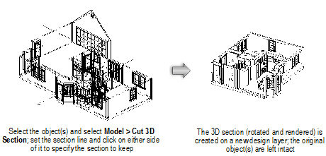
The cutting section commands define a section line through a 3D model, placing the cut section on a new layer and leaving the original model intact.
Creating section viewports (Vectorworks Design Series required) may be preferable to creating cutting sections.
The Cut 2D Section command creates a cross-section, or 2D contour, on the cutting plane. The contour is created by the intersection of the model with an infinite plane passing though the section line. Only the elements that actually intersect the section line are shown.
The Cut 3D Section command creates a section with all the 3D geometry that remains on the indicated side of the infinite plane passing through the section line. The elements that intersect the section line, as well as the 3D geometry that exists beyond the line, are shown.
Place a 2D section, along with a bold line, on top of a 3D section, to show the cutting plane with the section behind it.
~~~~~~~~~~~~~~~~~~~~~~~~~
The Cut 3D Section command cuts a 3D section, or slice, through a 3D model while leaving the model intact. The slice is placed on a new design layer.
To cut a 3D section from a 3D model:
1. Select the 3D model to section.
2. Select Model > Cut 3D Section.
The cursor changes to cross-hairs.
3. Click to set the start of the section. Draw a line across the object to define the section, and then click to set the end of the section.
When cutting a section while the drawing is in a Plan projection, the cutting plane (and the cut edge of the object) is perpendicular to the active layer plane.
When cutting a section while in a 3D projection, the cutting plane is perpendicular to the working plane.
4. Click on one side of the line to indicate the portion of the model to keep.
The Vectorworks program automatically creates a new design layer and places the cut 3D section on it. The original layer remains intact. The new 3D section behaves like any other Vectorworks 3D object.
Dimensions and text are 2D objects; therefore, they do not rotate with the cut 3D section.
~~~~~~~~~~~~~~~~~~~~~~~~~
The Cut 2D Section command cuts a 2D section, or a slice, from a 3D model without affecting the model. The slice is then placed on a new design layer. For example, to show the profile or a 2D cutaway section of an object in a mechanical 3D drawing, use this command to create the cutaway section in 2D quickly and easily, without affecting the original object.
To cut a 2D section from a 3D model:
1. Select the 3D model to section.
2. Select Model > Cut 2D Section.
The cursor changes to cross-hairs.
3. Click to set the start of the section. Draw a line across the object to define the section, and then click to set the end of the section.
When cutting a section while the drawing is in a Plan projection, the cutting plane (and the cut edge of the object) is perpendicular to the active layer plane.
When cutting a section while in a 3D projection, the cutting plane is perpendicular to the working plane.
4. Click on one side of the line to indicate the portion of the model to keep.
The Vectorworks program automatically creates a new design layer and places the cut 2D section on it. The original layer remains intact.
Layers are independent of each other. Each design layer has its own scale, view, and render status. In the Vectorworks Fundamentals product, however, a layer link can be created that combines the geometry of several design layers, including referenced layers, onto a single design layer. The linked objects on this design layer display in the same view and scale, and share the same render status. This can then be used to give an accurate depiction of how objects in each layer work together. For example, the various floors of a building can be drawn on separate layers and then linked together into a new layer to form an entire building.
In the Vectorworks Fundamentals product, consider using viewports instead of layer links, as they provide a better and easier way to present drawings.
In the Vectorworks Design Series products, layer links are being superseded by design layer viewports. For backward compatibility, the Create Layer Link command can still be added to any of the Vectorworks Design Series workspaces, and existing layer links can still be viewed and edited. For information on design layer viewports, see “Creating Design Layer Viewports” on page 1616.
The layer link is created on a new design layer that contains links to the existing design layers of the drawing. 3D objects on selected layers are automatically linked; 2D planar or screen objects can be displayed in the layer link. Once the layer link is created, updates to the design layers are automatically reflected on the linked layer when a screen redraw occurs. However, this updating occurs only in one direction; any new objects or details added to the linked layer will not appear in any other layers. Linked objects cannot be edited on the linked layer; they must be edited on their source layer.
To create a layer link:
1. Create a new layer, and then make it the active layer.
This layer shows objects on all linked layers and any changes made to them.
2. Select View > Create Layer Link.
The Create Layer Link dialog box opens; the layer being linked to (the currently active layer) is not listed.
Click to show/hide the parameters.
3. Select the design layers to be linked from the list of existing layers.
4. Click OK.
Linked layers are locked objects. To unlock a linked layer, select Modify > Unlock. Double-click on an item in the layer link to return to its source layer and edit it.
To project 2D planar or screen objects after a layer link has been created, select and then unlock the layer link object. Select the options in the Object Info palette.
~~~~~~~~~~~~~~~~~~~~~~~~~
Layer link objects can be cropped in a similar manner to viewports (see “Cropping Sheet Layer or Design Layer Viewports” on page 1648), although the area outside of the crop cannot be displayed as it can for a sheet layer or design viewport. When cropped, only a portion of the layer link displays; increase the scale of the layer to create a detailed view. Layer links with workgroup-referenced layers can also be cropped.
To crop a layer link:
1. Select an existing layer link.
2. Unlock the layer link by selecting Modify > Unlock.
3. Click Edit Crop from the Object Info palette to enter the Layer Link Crop mode.
Alternatively, right-click (Windows) or Ctrl-click (Mac) on a layer link and select Edit Crop from the context menu.
A colored border around the drawing window indicates that you are in an editing mode. The Exit Layer Link command becomes available from the Modify menu, and the Exit Layer Link Crop button displays in the top right corner of the drawing window.
4. Create a 2D object such as a rectangle, circle, or polyline. The 2D object must define an area; a 2D line, for example, cannot be used. Position the 2D object to delimit the new crop display area. The fill of a cropping object is always None; however, the pen style can be set from the Attributes palette while in Edit Crop mode. Set the pen style to None (or the crop object class to invisible) to make the crop object invisible. Move and resize the 2D object as needed.
To view other objects while in Edit Crop mode, select Show other objects while in editing modes on the Display tab of the Vectorworks preferences (see “Vectorworks Display Preferences” on page 48).
Use the Flyover tool to adjust the view as necessary (see “Flyover” on page 1140).
5. Click Exit Layer Link Crop, or select Modify > Exit Layer Link to return to the drawing.
The cropped layer link is displayed. In the Object Info palette, the crop status has changed to Yes.
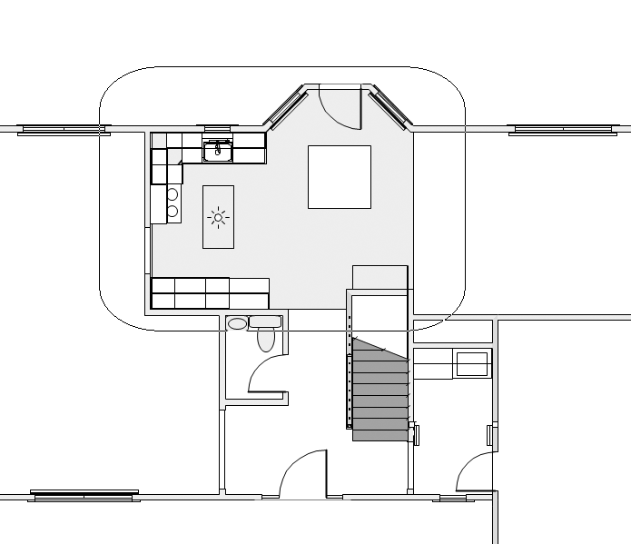
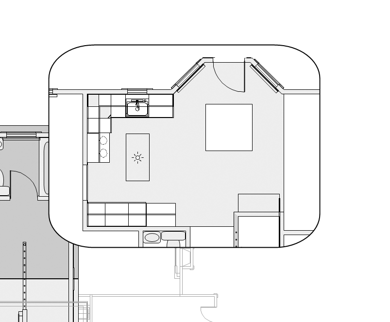
By increasing the scale of the layer with the layer link, and making other layers visible, a floor plan can be displayed (original design layer) along with a detailed view of the floor plan (zoomed in, cropped layer link).
To change, replace, or delete the layer link crop, select the cropped layer link and then select Edit Crop from the Object Info palette to re-enter crop mode. Click Exit Layer Link Crop, or select Modify > Exit Layer Link to return to the drawing.
The entire layer link is displayed if a viewport of a cropped layer link is created.
~~~~~~~~~~~~~~~~~~~~~~~~~
In the Vectorworks Design Series products, layer links are being superseded by design layer viewports. Because users of the Vectorworks Fundamentals product cannot create design layer viewports, and users of the Vectorworks Design Series products cannot create layer links, it occasionally may be necessary to convert a layer link into a viewport, or to convert a design layer viewport into a layer link.
• To convert a layer link into a design layer viewport, first unlock the layer link. Then, right-click (Windows) or Ctrl-click (Mac) on the layer link, and select Convert to Viewport from the context menu.
• To convert a design layer viewport into a layer link, select the viewport and then select Modify > Decompose. The Object Info palette changes to indicate that the object is now a group. Select Modify > Ungroup to create a layer link.
 Records
and Schedules
Records
and SchedulesSome architectural elements (doors and spaces, for example) have pre-defined data that is automatically attached to them as they are created. Pre-formatted schedules are available for reporting this data, as well as data from other elements of the Vectorworks Architect, Landmark, and Spotlight products. (For information on choosing a preformatted schedule in Vectorworks Landmark and Spotlight, see “Creating Schedules Automatically” on page 1314).
Typically, custom data records and schedules are created and edited with the Resource Browser. The Record and Schedule Management suite provides an alternate method for managing data in architectural documents.
For information about using the Resource Browser to create and edit record formats and schedules (worksheets), see “Record Formats” on page 258 and “Creating Worksheets” on page 1311. Record formats and schedules created in this way cannot be used with Vectorworks Architect product’s Record and Schedule management suite, however.
The records and schedules suite includes the following commands:
• VA Records and Schedules: Establishes default formats for records that can be attached to objects, and for schedules that can be generated from those records
• VA Create Record: Adds selected record formats to the current file
• VA Create Schedule: Adds selected schedules to the current file
By default, records and schedules created with VA Records and Schedules are added to the VA Defaults project preference set, and new files use that VA Defaults set. If additional sets of records and schedules are needed, create a new set of preferences and select that set before setting up a new drawing file. See “Working with Project Preference Sets” on page 1860 for more information.
~~~~~~~~~~~~~~~~~~~~~~~~~
 Defining
Records and Schedules
Defining
Records and SchedulesUse the VA Records and Schedules command to create and modify a set of record format and schedule definitions that can be used in any file.
After defining record formats and schedules, make them available in the current file using the VA Create Record and VA Create Schedule commands.
~~~~~~~~~~~~~~~~~~~~~~~~~
 Editing
Record Definitions
Editing
Record DefinitionsTo edit a record definition:
1. Select Tools > Reports > VA Records and Schedules.
The Records and Schedules dialog box opens.
Click to show/hide the parameters.
2. Select the record to edit.
3. Click Edit in the Records section of the Records and Schedules dialog box.
The Record Formats dialog box opens.
Click to show/hide the parameters.
4. Click Add to add a new record field or click Edit to edit the selected field.
The Edit Field dialog box opens. Add or edit the field information.
Click to show/hide the parameters.
5. Click OK to close the Edit Field dialog box.
6. In the Record Formats dialog box, continue to modify, add, or remove record items.
7. Click OK to close the Record Formats dialog box, and then click Done to close the Records and Schedules dialog box.
Once a record definition has been updated, instances of the new record format cannot co-exist in the same file with instances of the old record format. If an object is inserted into a drawing with a record format that differs from the current record of the same name, a dialog box opens requesting which format to retain. Records in the un-retained format will be purged, and their information will be lost. For this reason, it is recommended that any changes be made to record formats prior to beginning a project.
~~~~~~~~~~~~~~~~~~~~~~~~~
 Adding
Record Definitions
Adding
Record DefinitionsTo add a record definition:
1. Select Tools > Reports > VA Records and Schedules.
The Records and Schedules dialog box opens.
2. Click Add in the Records section of the Records and Schedules dialog box.
The Enter Text dialog box opens. Enter the name of the new record.
3. Click OK.
The Record Formats dialog box opens, listing the default fields of the new record; only the Add button is enabled.
4. Click Add to add a new field to the current record definition. Enter a Name and Default value for the field. Select the field Type from the list.
5. Click OK to close the Edit Field dialog box.
The new field displays on the Record Formats dialog box. If more fields are needed, repeat steps 4 and 5.
6. Click OK.
The new record and its fields are added to the record definition list.
7. Click Done to close the Records and Schedules dialog box.
~~~~~~~~~~~~~~~~~~~~~~~~~
 Removing
Record Definitions
Removing
Record DefinitionsTo remove a record definition:
1. Select Tools > Reports > VA Records and Schedules.
The Records and Schedules dialog box opens.
2. Select the record to remove.
3. Click Remove in the Records section of the Records and Schedules dialog box. This operation cannot be undone; click Yes to confirm that the record should be removed.
The record definition is removed from the record list.
4. Click Done to close the Records and Schedules dialog box.
~~~~~~~~~~~~~~~~~~~~~~~~~
 Editing
Schedule Definitions
Editing
Schedule DefinitionsThe Schedule definitions detail the column heading text, width, and border attributes for each record field being reported.
To edit a schedule definition:
1. Select Tools > Reports > VA Records and Schedules.
The Records and Schedules dialog box opens.
2. Select the schedule to edit.
3. Click Edit in the Schedules section of the Records and Schedules dialog box.
The Edit Schedule Format dialog box opens. Specify the schedule appearance by selecting the column order and formatting.
Click to show/hide the parameters.
4. Click Options to edit the schedule font style and size.
The Schedule Format Options dialog box opens; the current font type and size settings for the heading, subheadings, and body display.
5. If different font settings are desired, click the appropriate Change button to open the Format Text dialog box and modify the font type and size for the heading, subheadings, and body of schedule items. (See “Formatting Text” on page 385.)
6. Click OK to close the Schedule Format Options dialog box, and then click OK to close the Edit Schedule Format dialog box.
7. Click Done to close the Records and Schedules dialog box.
~~~~~~~~~~~~~~~~~~~~~~~~~
 Adding
Schedule Definitions
Adding
Schedule DefinitionsTo add a schedule definition:
1. Select Tools > Reports > VA Records and Schedules.
The Records and Schedules dialog box opens.
2. Click Add in the Schedules section of the Records and Schedules dialog box.
The Enter Text dialog box opens.
3. Enter the name for the new schedule.
4. Click OK.
The Edit Schedule Format dialog box opens. For details on the Edit Schedule Format dialog box parameters, see “Editing Schedule Definitions” on page 1856.
5. Select the record that defines the data to be reported in the new schedule, and then add the desired fields to use for the schedule.
6. Select a schedule column, and then enter the column formatting information. If desired, click Options and set the font formatting for the column, and then click OK.
7. Click OK to save the new schedule.
The new schedule definition is added.
8. Click Done to close the Records and Schedules dialog box.
~~~~~~~~~~~~~~~~~~~~~~~~~
 Removing
Schedule Definitions
Removing
Schedule DefinitionsTo remove a schedule definition:
1. Select Tools > Reports > VA Records and Schedules.
The Records and Schedules dialog box opens.
2. Select the schedule definition to remove.
3. Click Remove in the Schedules section of the Records and Schedules dialog box. This operation cannot be undone; click Yes to confirm that the schedule should be removed.
The schedule definition is removed from the schedule list.
4. Click Done to close the Records and Schedules dialog box.
~~~~~~~~~~~~~~~~~~~~~~~~~
 Creating Records
The VA Create Record command adds record formats created with the VA Records and Schedules command to the current file. Once the records are added, they can be attached to items in the drawing using the ID Label tool. They can also be attached by selecting an object and then selecting the check box next to the record format in the Data tab of the Object Info palette.
To create a record:
1. Select Tools > Reports > VA Create Record.
The Create Record dialog box opens, listing the available records that can be added to the file.
2. Select the record to add to the file.
3. Click OK to add the specified record to the file.
 Creating Schedules
The VA Create Schedule command generates worksheets for the current file. Any schedule definitions that were created with the VA Records and Schedules command display in the list, as well as several pre-formatted schedules provided as default content with the Vectorworks Architect product.
The Display default content option must be selected on the Session tab of Vectorworks preferences to see the pre-formatted schedules. (See “Session Preferences” on page 50.)
Pre-formatted schedules include:
• Diffuser Report |
• Objects with IFC Entity |
• Plant List - Simple w/Images |
• Door Hardware Legend |
• Objects with IFC Entity - Specific |
• Plant List - Types |
• Door Schedule |
• Objects without IFC Entity |
• Plumbing Schedule |
• Door Schedule w/Images |
• Plant List - Basic |
• Roof Face Area |
• Drawing List |
• Plant List - Basic w/Images |
• Room Finish Schedule |
• Equipment Schedule |
• Plant List - Colors |
• Wall Area |
• Existing Tree Schedule |
• Plant List - Colors w/Images |
• Wall Style Report |
• Existing Tree Schedule w/Images |
• Plant List - Costing |
• Wall Style Report w/Images |
• Irrigation Head Schedule |
• Plant List - Costing w/Images |
• Window Schedule |
• Irrigation Line Schedule |
• Plant List - Simple |
• Window Schedule w/Image |
To generate a schedule:
1. Select Tools > Reports > VA Create Schedule.
The Create Schedule dialog box opens, listing the schedules that can be added to the file.
2. Select the desired schedule to be created. Enter a new Schedule Title if desired. Select Place worksheet on drawing to place the worksheet on the drawing for printing.
Each schedule has a record format associated with it. If there is a difference between the record definition currently in the file and the record definition in the current preference set, a notice displays with the option to continue or fix the record.
If the selected schedule already exists in the file, a warning dialog box opens. Select whether to replace or rename the new schedule (some schedules also have a recalculate option), and click OK.
4. Click on the drawing area where the top left corner of the schedule is to be located.
The worksheet opens, displaying the schedule information. If the option to place the worksheet on drawing was selected, the worksheet is included on the drawing.
If the “on drawing” worksheet is accidentally deleted, select the worksheet name from the Resource Browser and select Resources >Worksheet On Drawing.
~~~~~~~~~~~~~~~~~~~~~~~~~
 Creating
a Room Finish Legend
Creating
a Room Finish LegendThere can be dozens of room finishes assigned within a project file. To obtain a detailed report of all room finish data, first generate a room finish schedule as described in “Creating Schedules” on page 1858. Then generate a detailed legend showing a full description of the finishes using the Create Rm Finish Legend command. This command can only be used after room finishes have been assigned to space objects.
To generate a room finish legend:
1. Select Tools > Reports > Create Rm Finish Legend.
The Create Room Finish Legend dialog box opens.
Click to show/hide the parameters.
2. Select whether the legend should be displayed as a text block or as a worksheet. See “Creating Text Blocks” on page 380 and “Creating Worksheets” on page 1311.
Display Method |
Description |
|---|---|
Text block |
Define the area for the legend to occupy. Click to set the top left corner of the text block, and then click to set the bottom right of the text block. The text legend is generated within the defined rectangle. |
Worksheet |
The worksheet is created with the legend information. If the Place worksheet in document option is selected, click on the drawing to set the top left corner of the worksheet. |
3. Click OK.
~~~~~~~~~~~~~~~~~~~~~~~~~
 Working
with Project Preference Sets
Working
with Project Preference SetsIn most cases, the default project preference set (VA Defaults) is the only set needed. If additional sets of records and schedules are needed, create a new set of preferences and select that set before setting up a new drawing file.
A project preference set is a grouped configuration of record, schedule, and library information that is used by a drawing file. A project preference set can be customized for particular projects (residential or commercial, for example) or different types of clients (restaurant or retail store, for example). Different record and schedule formats can be assigned, as well as information in room finish libraries and door hardware libraries. These custom configurations are saved in external text files. The VA Set Project Prefs command assigns which set of external files to use within the current drawing. The settings files used by these commands, taken together, are called a “project preference set.” Dialog boxes in the Vectorworks Architect product’s Record and Schedule management suite display the name of the current preference set in the title bar.
Because the preference sets are stored as external files, they can be shared among many users to comply with office standards. The preference set folders can be copied to the same location for each user, or shared on a network location. Either select the VA Set Project Prefs command to designate the preference set location, or copy the following text file to each computer:
[Vectorworks]\Plug-Ins\VW_Arch\Data\VA2_Preference_Set_Paths.txt
See “Project Preference Sets” on page 1891 for information on the files contained in the preference set folders.
~~~~~~~~~~~~~~~~~~~~~~~~~
 Selecting
a Project Preference Set
Selecting
a Project Preference SetThe default preference set is named “VA Defaults,” and its files are located in [Vectorworks]\Plug-Ins\VW_Arch\Data\Prefs_Def.
To use a different project preference set, select it when setting up the file. The preference set selection is saved with the file. Changes to VA Records and Schedules, the Door Hardware Library, or the Room Finish Library are saved in the currently selected project preference set.
When using template files for different types of projects, make a preference set selection before saving the template.
To select a project preference set:
1. Select Tools > Options > VA Set Project Prefs.
The VA Preference Sets dialog box opens. The listed sets are available for use in the file.
Click to show/hide the parameters.
2. Select the project preference set to activate.
3. Click Done.
The selection “VA Defaults” cannot be deleted or edited; it contains the information that is used if no project preference set is designated or if there is an error finding the designated set.
~~~~~~~~~~~~~~~~~~~~~~~~~
 Creating
a New Project Preference Set
Creating
a New Project Preference SetWhile the Vectorworks Architect product installs with six project preference sets, it supports the use of an unlimited number. To add preference sets beyond the default options, manually create additional preference folders and then add the set to the list of defined sets using the VA Set Project Prefs command.
The project preference set folder must contain the following files for correct operation:
• Door Hardware Library.txt
• Equipment Record.txt
• Equipment Schedule.txt
• Plumbing Fixt Record.txt
• Plumbing Schedule.txt
• VA2 Records and Schedules.txt
• VA_Project_Set.txt
If additional records and schedules are defined using the VA Records and Schedules command, their data files are stored in the project preference set folder.
After creating a project preference set, add it to the list of project preference sets available:
1. Select Tools > Options > VA Set Project Prefs.
2. The VA Preference Sets dialog box opens. Click Add.
The Add Preference Set dialog box opens. Specify the name and location of the project preference set.
Click to show/hide the parameters.
3. Click OK to return to the VA Preference Sets dialog box. To use the new project preference set, select it from the list and click Done.
~~~~~~~~~~~~~~~~~~~~~~~~~
 Creating
a Human Figure
Creating
a Human FigureA 3D human figure object can be inserted for a realistic addition to the drawing. Constructed of NURBS surfaces for a high-quality model, the object contains a wide variety of parameters for full control over the figure type, position, and appearance.
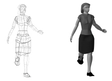
An entourage/figures object library also contains pre-configured human figure objects in a variety of poses and figure types (see “Resource Libraries” on page 215).
Several figures can increase the time required to render the model in 3D.
~~~~~~~~~~~~~~~~~~~~~~~~~
 Inserting
the Figure and Setting Parameters
Inserting
the Figure and Setting Parameters
To insert and configure a human figure:
1. Click the Human Figure tool from the Visualization tool set.
2. Click to place the human figure in the drawing.
3. The human figure parameters can be modified from the Object Info palette.
Click to show/hide the parameters.
~~~~~~~~~~~~~~~~~~~~~~~~~
 Setting
Figure Attributes
Setting
Figure AttributesFigure attributes can be set precisely to control the figure appearance.
To set figure attributes:
1. Select the desired figure.
2. In the Object Info palette, make the initial selections for the figure.
3. Click Set Attributes from the Object Info palette.
The Human Figure Attributes dialog box opens, with the figure set to the current Object Info palette parameters. Select each desired model part and then set its attributes.
Click to show/hide the parameters.
For more information on texture parameters and mapping, see “Applying and Mapping Textures” on page 1523.
4. Click OK to apply the attributes to the figure.
~~~~~~~~~~~~~~~~~~~~~~~~~
 Specifying
a Custom Figure Position
Specifying
a Custom Figure PositionIf the Posture selection is not sufficient to position the figure exactly as desired, a custom figure pose can individually position the figure’s head, body, arms, and legs.
Use the Rotate tool to set the overall position of the figure.
To specify a custom figure pose:
1. Select the desired figure.
2. In the Object Info palette, make the initial parameter selections for the figure.
3. Click Custom Position from the Object Info palette.
The Figure Custom Position dialog box opens, with the figure set to the current Object Info palette parameters. Select the body part tab to change, and then set the part parameters by dragging the slider for the desired settings.
Use slight slider adjustments for best results.
Click to show/hide the parameters.
4. Click OK to apply the custom position to the figure.
~~~~~~~~~~~~~~~~~~~~~~~~~
 Exporting
for DOE-2 Requirements
Exporting
for DOE-2 RequirementsWith rising energy costs and stricter regulations on energy usage in commercial buildings, it is becoming increasingly important to be able to estimate the energy cost implications of design strategies, especially during the schematic design phase. Energy usage programs develop these estimates. The Vectorworks Architect product can export the building geometry to a file in the format read by the DOE energy analysis engine.
To create a DOE-2 export file:
1. The initial building space planning should be complete, with layers for all the building levels and spaces on those layers. Exterior walls are also required; create these automatically with the Create Walls from Spaces command, or manually.
Windows and doors should also be inserted into the walls where appropriate.
2. Select AEC > Space Planning > Export DOE-2.
The Export DOE-2 dialog box opens.
Click to show/hide the parameters.
3. Click OK to create the DOE-2 text file. Send the file to your DOE consultant for analysis.
The relationship between Vectorworks entities and their corresponding BDL language entities is shown in the following table.
Vectorworks |
DOE |
|---|---|
Distance from layer Z to next highest layer Z |
Floor height |
Layer delta-Z |
Space height |
Description field in wall record |
Construction type |
Wall record R-value |
Construction type U-Factor |
Window vs. door record |
Window vs. door |
~~~~~~~~~~~~~~~~~~~~~~~~~
 Generating
an INP File from a DXF File
Generating
an INP File from a DXF FileIf .INP files need to be generated from DXF files for analysis with the DOE-2 engine, several steps are required to properly import and format the file in the Vectorworks Architect product prior to exporting it.
AutoCAD building plans are often broken up into several files, which are then cross-referenced (x-ref) to a master file. Prior to importing into a Vectorworks file, all of these files must be pulled into the master file. Essentially, all of the information about a building must be present in one file for the export to recognize the relationships among adjacent building levels and spaces on each of those floors. See “DXF/DWG and DWF File Import” on page 1710.
Vectorworks classes are roughly equivalent to AutoCAD layers. When importing the DXF file, the layers should be imported as Vectorworks classes. The Vectorworks program allows the specification of the base elevation (Z value) of layers; therefore, Vectorworks layers are typically used to separate the different building levels in the drawing. Once these layers have been established with the appropriate Z values, it is much easier to draw on the layers without having to specify base heights of each object.
The Export DOE-2 command uses the layer Z values to determine the Z value of each floor in the INP file. After importing a DXF file, first create a layer for every building level, and then assign a Z value to that layer. In addition, assign a delta Z value. In a normal drawing created with the Vectorworks Architect product, the delta Z controls the default height (at object creation time) of all walls on that layer. The Export DOE-2 command uses the delta Z as the space-height.
To create a layer for a building level, select Tools > Organization. On the Design Layers tab, create and set properties for the building level layer. See “Creating Layers” on page 158 and “Setting Design Layer Properties” on page 161.
Once the layers have been defined, define the spaces. Polygons may already exist for all the spaces; if so, convert the polygons to spaces with the Create Spaces from Polys command (see “Space Settings” on page 402).
The Vectorworks program has a dedicated object type for walls. A Vectorworks wall is a complex object type which is a combination of lines, arcs (in the case of rounded walls), polygons/polylines, and fill patterns. The Vectorworks Architect product adds more functionality to wall objects by attaching a record with a description field.
The Export DOE-2 command checks for wall objects along the perimeter of the spaces in the drawing. If walls are found, it checks for a wall record. If this is found, the description field is exported as the construction type for that segment. If no wall record is present, the command exports the wall’s class name as the construction type. If it does not find a wall object on any particular space vertex, a default construction type for the wall on that vertex is assigned. The default construction types are “Default Exterior Wall” construction and “Default Interior Wall” construction.
If the walls in the original DWG file were drawn with multi-lines, importing the multi-lines as Vectorworks walls is recommended. If the original draftsperson did not use multi-lines, then the walls must be manually drawn. The walls must be on the same layer as their respective space objects. In other words, first floor walls must be on the same layer as the space objects for the first floor.
The Export DOE-2 command determines the difference between windows and doors on the basis of the attached record. If the symbol has a door record attached, the symbol is exported as a door. If it has a window record attached to it, or no record at all, it is exported as a window.
To export windows and doors, walls are required. Inserting windows and doors into Vectorworks walls is much easier than creating them mathematically within the DOE-2 interface. Vectorworks walls normally “contain” the windows and doors, essentially as nested objects. The associativity of windows and doors with their parent walls allows the Export DOE-2 command to recognize which windows/doors are associated with which walls, and export them to the appropriate place in the INP file. Ensure that when inserting the windows and doors into the walls, they create a wall break. Otherwise, they are not considered associated with the wall.
AutoCAD blocks can be used, which convert to Vectorworks symbols during the DXF import. The length of the window/door, parallel to the wall, is exported as the width. For windows, the elevation of the lowest part of the window is exported as the Y value.
 Cam
Design
Cam
DesignThe cam design tool can be animated and generates cam data worksheets and diagrams.
~~~~~~~~~~~~~~~~~~~~~~~~~
 Cam
Template
Cam
TemplateTo use the cam design tool, open a new file and select the Cam (Imperial).sta or Cam (Metric).sta template.
To open the cam template:
1. Select File > New.
The Create Document dialog box opens.
2. Select Use document template, and choose the Cam (Imperial).sta or Cam (Metric).sta template.
3. Click OK. The new file opens, with a cam inserted by default. The file contains Cam and Diagrams layers.
The recommended procedure to include a cam in a Vectorworks drawing is to copy and paste it into the drawing, and convert it to a group by selecting it and selecting Modify > Convert > Convert to Group.
~~~~~~~~~~~~~~~~~~~~~~~~~
 Cam
Properties
Cam
PropertiesThe cam object is a point object located in the Cam (Imperial).sta and Cam (Metric).sta templates. Cam properties can be edited in the Object Info palette.

Click to show/hide the parameters.
~~~~~~~~~~~~~~~~~~~~~~~~~
 Defining
the Cam Profile
Defining
the Cam ProfileSpecify the profile of each cam segment in the Define Cam Profile dialog box.
To define the cam profile:
1. Select the cam, and click Define Cam Profile on the Shape tab of the Object Info palette.
The Enter Value dialog box opens.
2. Enter the number of cam segments and click OK.
The Define Cam Profile dialog box opens for specifying the parameters for each segment. Click OK to update cam diagram.
Click to show/hide the parameters.
 Animating
Cam Movement
Animating
Cam MovementThe effect of parameter changes to the cam design can be evaluated by animating the cam.
To animate the cam:
1. Select the cam, and in the Object Info palette, click Animate.
The Rotate Cam dialog box opens.
2. Adjust the relative speed by moving the slider along the Speed bar.
3. Click Rotate.
The cam rotates at the relative speed specified and the follower moves accordingly.
Since the animation is for illustrative purposes only, the Cam Speed parameter does not affect the animation. However, the animation is affected by the selected speed in the Rotate Cam dialog box; the larger the increment, the faster the cam appears to rotate. In addition, the computer processor speed also affects the apparent animation speed.
4. To stop the cam rotation, press any key or click anywhere on the screen.
Once the cam rotation stops, the position of the cam remains where it was when it was stopped. To reset the cam to zero degrees (original position), click Reset Cam to 0 on the Shape tab of the Object Info palette.
 Cam
Data Worksheets
Cam
Data WorksheetsTwo worksheets are defined in the Cam (Imperial).sta and Cam (Metric).sta templates:
• Cam Data – lists cam data, such as rotation angle, follower displacement, velocity, and acceleration
• Cam Properties – lists the cam parameters from the Object Info palette
The worksheets are accessed by selecting them from the Window > Worksheets menu or from the Resource Browser. The Cam Properties worksheet updates when the Define Cam Profile dialog box is exited (see “Defining the Cam Profile” on page 1872). The Cam Data worksheet updates when the cam properties are changed. The worksheets can be placed on the drawing as graphic objects, if desired (see “Worksheets as Graphic Objects” on page 1356).
To prevent slower performance, when changing cam properties, keep the Cam Data worksheet closed.
~~~~~~~~~~~~~~~~~~~~~~~~~
 Cam
Diagrams
Cam
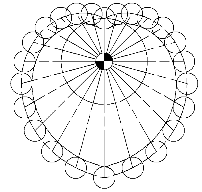
DiagramsDiagrams of the cam follower displacement, velocity and acceleration are created automatically from the current cam properties.
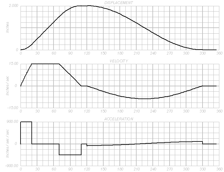
The diagrams exist on the Diagrams layer.
To display or update the diagrams:
1. Select the Draw Cam Diagrams command from the appropriate menu:
• Architect: AEC > Machine Design > Draw Cam Diagrams
• Landmark: Landmark > Machine Design > Draw Cam Diagrams
• Spotlight: Spotlight > Machine Design > Draw Cam Diagrams
2. The cam diagrams are displayed. To return to the cam, select Cam from the Layers list on the View bar.
~~~~~~~~~~~~~~~~~~~~~~~~~
 Geneva Mechanism
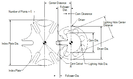
The Geneva mechanism device produces intermittent rotational motion of the driven part (index plate) while the driver rotates at a constant speed.
~~~~~~~~~~~~~~~~~~~~~~~~~
 Geneva
Mechanism Template
Geneva
Mechanism TemplateThe Geneva mechanism is available in the Geneva Mechanism (Imperial).sta and Geneva Mechanism (Metric).sta template files.
To open the Geneva mechanism template:
1. Select File > New.
The Create Document dialog box opens.
2. Select Use document template, and choose the Geneva Mechanism (Imperial).sta or Geneva Mechanism (Metric).sta template.
3. Click OK.
The new file opens with a Geneva mechanism inserted by default.
The recommended procedure to include a Geneva mechanism in a Vectorworks drawing is to copy and paste it into the drawing and convert it to a group by selecting it and selecting Modify > Convert > Convert to Group.
~~~~~~~~~~~~~~~~~~~~~~~~~
 Geneva
Mechanism Properties
Geneva
Mechanism PropertiesThe Geneva mechanism’s properties can be edited in the Object Info palette.
Click to show/hide the parameters.
~~~~~~~~~~~~~~~~~~~~~~~~~
 Animating
Geneva Mechanism Movement
Animating
Geneva Mechanism MovementThe effect of parameter changes to the Geneva mechanism design can be evaluated by animating the Geneva mechanism.
To animate the Geneva mechanism:
1. Select the Geneva mechanism, and in the Object Info palette, click Animate.
The Rotate Geneva Mechanism dialog box opens.
2. Adjust the relative speed by moving the slider along the Speed bar.
3. Click Rotate.
The Geneva mechanism rotates at the relative speed specified.
4. To stop the Geneva mechanism rotation, press any key or click anywhere on the screen.
Once the mechanism rotation stops, the position of the mechanism remains where it was when it was stopped. To reset the mechanism to zero degrees (original position), click Reset Mechanism to 0 on the Shape tab of the Object Info palette.
 Notes
Manager Database Format
Notes
Manager Database FormatThe Notes Manager, in version 11 and later, can use a database from an outside source, provided that it has been formatted appropriately. Data files must be in one of two formats: a version 11 or later format, or the format used by the Notes Manager in versions of Vectorworks software previous to version 11. The format used by previous versions may be somewhat simpler to use, and is automatically converted to the current format by the Notes Manager.
The database format must adhere to the following requirements to be recognized as a database from versions of the Notes Manager prior to 11.
• The first line must contain only a numeric value
• The rest of the file must contain notes with the following data separated by tabs:
• a numeric value
• a dash
• the section name
• the description
• the note text
• Additional tabs or carriage returns are not allowed within each field
• There can be no blank lines before the end of the file
This format is illustrated by the following example.
3 |
|
|
|
|
00 |
- |
Section 1 |
Description 1 |
This is keynote 1. |
00 |
- |
Section 1 |
Description 2 |
This is keynote 2. |
00 |
- |
Section 1 |
Description 3 |
This is keynote 3. |
The database format must adhere to the following requirements to be recognized as a database from version 11 and later Notes Manager.
• The first line must contain the word “NotesManager11DataFile”
• The second line must contain the database ID (unique for all databases used)
• The rest of the file must contain notes with the following data separated by tabs:
• a note ID (unique for all notes in the file)
• the section name
• the description
• the note text
• After the notes, an optional section can identify which description was last selected in each section
• Additional tabs or carriage returns are not allowed within each field
• There can be no blank lines before the end of the file
The database and note IDs are in the format of “ID_#”, where “#” represents any numeric value with not more than 14 digits and no decimal point. Notes Manager does not change these IDs after creation, but when new notes are added, it uses IDs similar to those shown in the following example.
Notes Manager11DataFile |
|
|
|
ID_04030110200020 |
General Project Notes |
Scope of Work |
Project located at ‘ADDRESS’,’CITY’,’STATE’, county of ‘COUNTY’. |
ID_04030110200021 |
General Project Notes |
Accessibility Compliance |
Project complies with accessibility standards. |
ID_04030110200022 |
General Project Notes |
Involved Parties |
“Owner” refers to ‘OWNER ID’ or its authorized representatives. |
0 |
End of Notes |
|
|
General Project Notes |
Scope of Work |
|
|
 Adding
User-defined Information to Commands
Adding
User-defined Information to CommandsCertain commands permit adding to the list of available values for certain parameters (for example, the Material list for the Spring Calculator or the Units list for the Simple Beam command).
Parameters Allowing Addition of User-defined Values in the GetUserData.vss File |
|||
Group |
Plug-in Object |
Parameter |
Dialog Box |
1 |
Spring Calculator |
Units (inches, mm and cm only) |
Spring Calculator |
|
Shaft Analysis |
Outside Diameter |
Shaft Analysis |
|
Simple Beam |
Beam Length |
Simple Beam: Set Beam Properties |
|
Simple Beam |
Deflection Units |
Simple Beam: Set Beam Properties |
2 |
Simple Beam |
These items are the singular form of the names in Group 1 and are used when writing the values to a worksheet and a text block on the drawing |
Not applicable |
3 |
Simple Beam |
Load Units |
Simple Beam: Add/Remove/Change Loads |
4 |
Simple Beam |
These items are the singular form of the names in Group 3 and are used when writing the values to a worksheet and a text block on the drawing |
Not applicable |
5 |
Simple Beam |
Section Modulus Units |
Simple Beam: Set Beam Properties |
6 |
Simple Beam |
Moment of Inertia Units |
Simple Beam: Set Beam Properties |
7 |
Shaft Analysis |
Shear Modulus Units |
Shaft Analysis |
|
Simple Beam |
Modulus of Elasticity Units |
Simple Beam: Set Beam Properties |
8 |
Spring Calculator |
Material |
Spring Calculator |
9 |
Shaft Analysis |
Twisting Moment Units |
Shaft Analysis |
~~~~~~~~~~~~~~~~~~~~~~~~~
 Adding
User-defined Spring Calculator Materials
Adding
User-defined Spring Calculator MaterialsThe following example shows how to add to the list of materials available to the Spring Calculator.
To add to the list of Spring Calculator materials:
1. Make a backup copy of the GetUserData.vss file, located in Plug-Ins\VW_Mech\Includes. Keep the backup copy in case there is a need to restore the GetUserData.vss file to its original state.
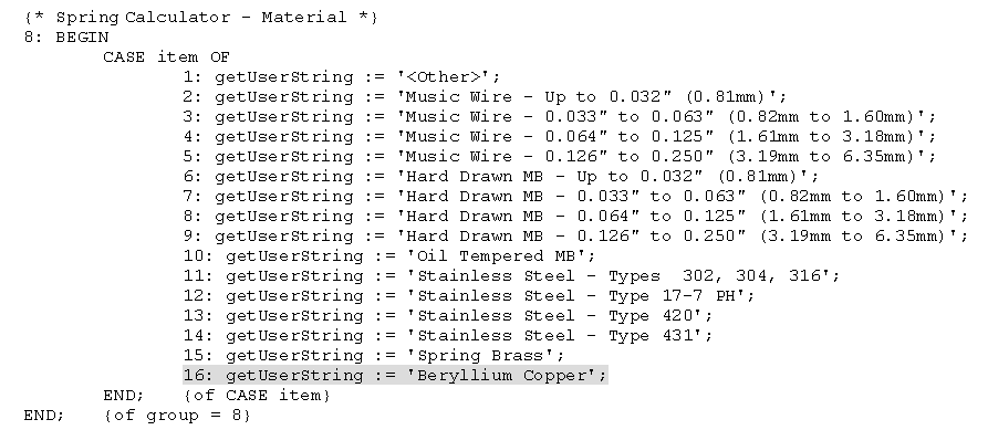
2. Open the GetUserData.vss file in any word processor and locate group 8 in the getUserString function.
3. Using the next available sequential number, add the new Material to the end of the list (in this example, Beryllium Copper). Enclose the name in single quotes and put a semi-colon at the end of the line. The new line should read:
16: getUserString := ‘Beryllium Copper’;
4. Locate group 8 in the getUserData function.
5. Using the next available sequential number, add the new Mod. of Elasticity value (in this example, pounds per square inch). The sequential number added here must correspond to the number added in the getUserString function. Put a semi-colon at the end of the line; do not use single quotes or commas in the value. The new line should read:
16: getUserData := 7000000;
6. Change the value of item 0 to the new group number, which indicates the number of available values (in this example, 16).
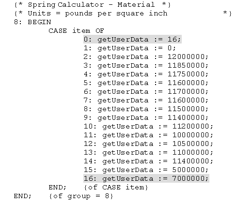
7. Save the file. The next time the Spring Calculator is run, the new item is available in the Material list, and when selected, the new value is available in the Mod. of Elasticity field. When executed, the Spring Calculator automatically recalculates the value to the user-specified units. (For beryllium copper, the value is 7,000,000 lb/in2.)
If the Spring Calculator was used during the current session, the Vectorworks program needs to be restarted for the changes to take place.
 Adding
User-defined Simple Beam Units
Adding
User-defined Simple Beam UnitsThe following example shows how to add to the list of available units for the Simple Beam command.
To add to the list of units for the Simple Beam command:
1. Make a backup copy of the GetUserData.vss file located in Plug-Ins\VW_Mech\Includes. Keep the backup copy in case there is a need to restore the GetUserData.vss file to its original state.
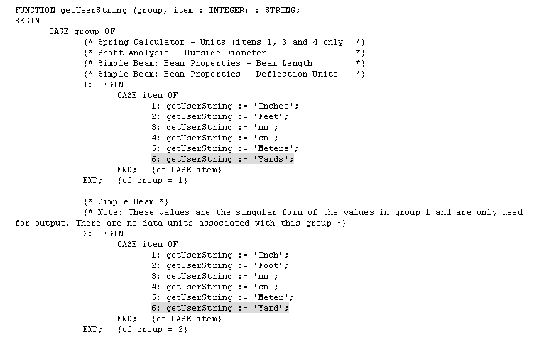
2. Open the GetUserData.vss file in any word processor and locate group 1 in the getUserString function.
3. Using the next available sequential number, add the new Units to the end of the list (in this example, Yards). Enclose the name in single quotes and put a semi-colon at the end of the line. The new line should read:
6: getUserString := ‘Yards’;
4. Locate group 2 in the getUserString function.
5. Using the next available sequential number, add the new Units to the end of the list. (In this example, type yard in the singular form; this value is used in certain output for the Simple Beam command and must have an entry corresponding to the same item in group 1).
Enclose the name in single quotes and put a semi-colon at the end of the line. The new line should read:
6: getUserString := ‘Yard’;
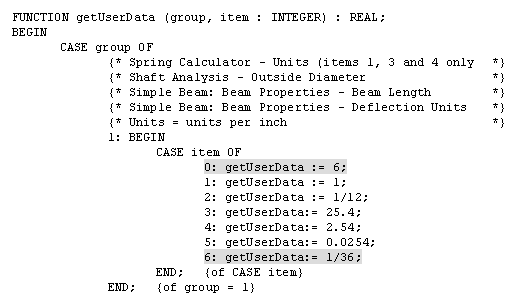
6. Locate group 1 in the getUserData function.
7. Using the next available sequential number, add the new Units to the end of the list (in this example, units per inch of a yard: 1/36). The sequential number added here must correspond to the number added in the getUserString function. Put a semi-colon at the end of the line; do not enclose the name in single quotes. The new line should read:
6: getUserData := 1/36;
8. Change the value of item 0 to the new group number, which indicates the number of available values (in this example, 6).
9. Save the file. The next time the Simple Beam command is used, the new item is available in the Beam Properties dialog box.
This change also affects the Shaft properties of the Shaft Analysis command. These values are also used by the Spring Calculator Units, but only items 1, 3, and 4 are applicable, so the new units (Yards) will not show up in this field.
 Simple
Beam and Spring Calculator Examples
Simple
Beam and Spring Calculator ExamplesThis section provides examples of using the Spring Calculator and Simple Beam commands to accomplish specific tasks.
~~~~~~~~~~~~~~~~~~~~~~~~~
 Spring
Calculator
Spring
CalculatorThe spring calculator can determine spring rates and unit stresses of round wire helical coil compression springs with known parameters. It can also be used to design a spring knowing the working values. This example is based on the following compression spring with closed and ground ends of music wire.

To calculate spring rate and unit stress:
1. Determine the required spring rate based on the deflection at a load divided by the difference in the working length and the free length. For this example, the desired spring rate equals 28.8 lb/in (36 lb/1.25 in = 28.8 lb/in).
2. Select the Spring Calculator command from the appropriate menu:
• Architect: AEC > Machine Design > Spring Calculator
• Landmark: Landmark > Machine Design > Spring Calculator
• Spotlight: Spotlight > Machine Design > Spring Calculator
The Spring Calculator dialog box opens.
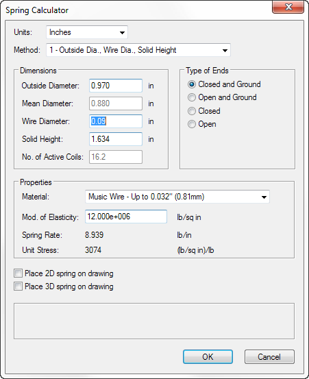
3. As shown in the above dialog box, select 1 - Outside Dia., Wire Dia., Solid Height from the Method list. After entering the known values, calculate a spring rate close to the desired value by trying several standard wire diameter values. Adjust the material in the Material list to fit the wire diameter used. Here, a wire diameter of .090” gives a spring rate of 8.94 lb/in.
4. In the Method list, select 2 - Mean Dia., Wire Dia., No. of Active Coils.
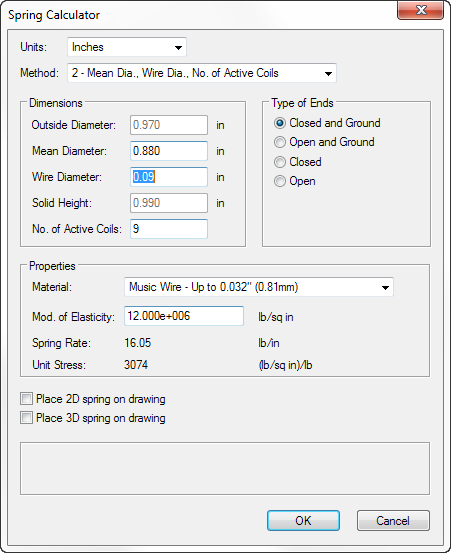
5. As shown in this dialog box, vary the wire diameter and number of active coils to get a spring rate close to the required spring rate. A wire diameter of .095” and 11 active coils gives a spring rate of 16.3 lb/in, but the solid height is 1.24”, which is too high. A wire diameter of .090” and 9 active coils, however, gives a spring rate of 16.1 lb/in, and a solid height of .990”, which is within acceptable limits.
6. Finally, check the stresses applied to the spring to verify that they are within acceptable limits. With a unit stress of 3074 (lb/sq in)/lb, multiply by 36 to obtain 110,663 lb/sq in. With a solid height of .990”, the stress will be:
(2.500-0.900)in x 16.1 lb/in x 3074 (lb/sq in)/lb = 79,200 lb/sq in
7. This value is below the safe working stress of 111,000 lb/sq in for this material and wire size.
 Simple Beam
This example shows how the Simple Beam commands can be used to find the stresses on the horizontal elements of a certain machine part.

To calculate the stresses:
1. Select File > New.
The Create Document dialog box opens.
2. Select Use document template, and choose the Simple Beam (Imperial) or Simple Beam (Metric).sta template.
3. Click OK.
4. Select the Simple Beam command from the appropriate menu:
• Architect: AEC > Machine Design > Simple Beam
• Landmark: Landmark > Machine Design > Simple Beam
• Spotlight: Spotlight > Machine Design > Simple Beam
The Simple Beam dialog box opens.
5. Click Configure Beam.
The Configure Beam dialog box opens.
6. Specify the beam properties. In this example, enter the following values:

To obtain the section modulus and moment of inertia of the tubing, select a tubing shape from the Resource Browser and place an instance of it on the drawing. Convert the tubing to a group and then use the Engineering Properties command to obtain the properties. For more information on the Engineering Properties command, see “Obtaining Engineering Properties” on page 1813.
7. Click OK to close the Beam Properties dialog box.
8. Click Define Loads on the Simple Beam dialog box.
The Define Loads dialog box opens.
9. Specify the load properties. In this example, use the following values:

10. Click OK close the Define Loads dialog box.
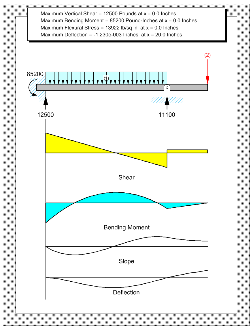
11. In the Simple Beam dialog box, click Calculate Reactions, and then click Calculate Stresses and Deflection, and then click OK.
A simple beam diagram is created based on the information provided. See “Simple Beam” on page 1882 for more information on what is depicted in the diagram.
 Layer,
Class, and Viewport Standards
Layer,
Class, and Viewport StandardsThe standards for the Vectorworks Architect and Landmark products are centered around the concept of viewports on sheet layers. A project file contains a number of viewports; each viewport consists of a particular combination of visible layers and classes.
This section provides information about the viewport, layer, and class standards in Vectorworks Architect and Landmark products. Modifying these standards is not recommended, as it requires a large effort to manage and coordinate standards information.
~~~~~~~~~~~~~~~~~~~~~~~~~
 Using
the Layermap Worksheet
Using
the Layermap WorksheetThe creation of layers, classes, and viewports or views by the setup commands (Create Standard Viewports and Standard Naming) is controlled through the use of the worksheet LayerMap.G, in the VA Setup Data-Imperial.vwx or VA Setup Data-Metric.vwx file ([Vectorworks]\Plug-Ins\Common\Data). This worksheet contains the predefined class, layer, attribute, and visibility information needed to generate a completely ready-to-use project file at any scale or level of complexity.
The LayerMap.G worksheet applies to viewports on sheet layers created with the Create Standard Viewports command, or views created with the Create Corresponding View for Each Viewport option in the Create Standard Viewports dialog box.
The settings in the LayerMap.G worksheet are automatically applied when a new file is opened and one of the Setup commands is selected. If the LayerMap.G worksheet contained in the VA Setup Data-Imperial.vwx or VA Setup Data-Metric.vwx file is edited, all sheets created on that machine will use the new standards. However, a copy of the LayerMap.G worksheet can be included in a file (by importing it) and edited there. These custom settings will supersede any automated settings for that file only. This is a convenient way of sharing standards between offices and users, without modifying the default standards on an individual machine.
If a Vectorworks file contains a LayerMap.G worksheet, when the Create Standard Viewports command is selected, the Import LayerMap.G dialog box opens. Specify which worksheet to use.
Click to show/hide the parameters.
~~~~~~~~~~~~~~~~~~~~~~~~~
 The
Layermap Worksheet
The
Layermap WorksheetThe Layermap worksheet, located in the VA Setup Data-Imperial.vwx or VA Setup Data-Metric.vwx file, begins with a listing of project types in the first six rows (before the LayerMap.G row). These project types are used by the legacy command Create Standard Views, and are not used by the Create Standard Viewports command. As such, they are no longer supported.
Following the legacy project types are the names of the viewports or views used by the Create Standard Viewports command. Below the name is the viewport/view type, which controls under which drawing type the viewport/view appears in the Create Standard Viewports dialog box.
After the project types section is the layers section. This section of the Layermap worksheet controls the initialization and setup of layers in a specific viewport/view. Based on the information in this section, the Create Standard Viewports command generates a complete array of layers with the proper settings to correctly display a viewport or view.

The final section in the Layermap worksheet is the classes section. This section controls class setup and initialization for each viewport/view. As with the layer section, the Setup commands use the information to generate a full class setup configuration for each viewport/view in a project file.
~~~~~~~~~~~~~~~~~~~~~~~~~
 Viewport/View
Types
Viewport/View
TypesViewport/view types are found directly under the viewport/view names in the Layermap worksheet. The identifier directly beneath the viewport/view name indicates its drawing type. Viewport/view types control how the viewport/view is generated, and are used by the Create Standard Viewports command to properly configure the project document. The viewport/view type identifier may take on one of the following values:
Identifier |
Drawing Type |
|---|---|
1 |
Project plan view/viewport (one viewport/view only) |
L |
Auxiliary viewport/view (create a user-specified number of viewports/views) |
M |
Floor plan viewport/view (create one viewport/view for each floor in the project) |
N |
Notation viewport/view (create a user-specified number of viewports/views) |
S |
Site plan viewport/view (create one viewport/view) |

 Standard
Layer Visibility in Viewports/Views
Standard
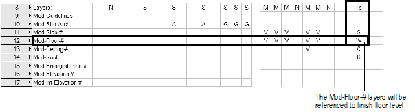
Layer Visibility in Viewports/ViewsIn the layers section of Layermap worksheet, layer names are listed down the left side of the worksheet in the first column. This listing represents the available layers that can be included in a viewport/view. Layer names that are used when generating multiple layers (for example, for the floor viewports/views of a multi-floor building) are indicated by a pound sign (#) suffix.
The visibility status of a specific layer is indicated by an alphabetic identifier located in the worksheet cell which cross-references the layer and the viewport/view in which it will be a component. The identifier can take on one of the following values:
Identifier |
Meaning |
|---|---|
A |
Active layer |
V |
Visible |
G |
Grayed |
I |
Invisible |
<no value> |
Not created for viewport/view; set to invisible if existing |

 Design
Layer Types in the Standards
Design
Layer Types in the StandardsThe Layermap worksheet contains a specialized set of identifiers which control how model design layers are configured for a project file. These identifiers, which are located on the extreme right of the Layermap worksheet opposite the model layers, are used by the Setup commands to correctly configure a set of model layers for the project file.
Model layer type identifiers can take on one of the following values:
Identifier |
Meaning |
|---|---|
C |
Layer w/ ceiling referenced information (one per floor) |
F |
Foundation layer (one per project) |
R |
Roof layer (one per project) |
S |
Slab layer (one per floor) |
W |
Layer w/ floor referenced information (one per floor) |
<no value> |
Supplemental model layer |
 Class
Visibility in the Standards
Class
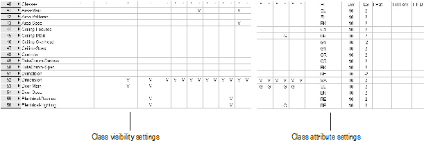
Visibility in the StandardsIn the class section of the Layermap worksheet, class names available for inclusion in the viewports/views are listed down the left side of the worksheet in the first column. The visibility of a specific class is indicated by an alphabetic identifier, which is located in the worksheet cell which cross-references the layer and the viewport/view.
The identifier can take on one of the following values:
Identifier |
Meaning |
|---|---|
V |
Visible |
G |
Grayed |
I |
Invisible |
<no value> |
Not created for viewport/view; set to invisible if existing |
An explanation of the specific uses of and applications for classes, including AIA layer name equivalents, is provided in PDF format (VA Sheet-Layer-Class stds.pdf) included with the Vectorworks Architect product and available in [Vectorworks]\Extras.
Default class attributes, such as line style and pen color, are no longer controlled from the Layermap worksheet.
 Auto-classing
Objects
Auto-classing
ObjectsCertain plug-in objects and symbols have specific default classes, which coordinate with the Layermap worksheet class name standards. The plug-in objects listed here are automatically classed when they are inserted into a file that is set up to use auto-classing (when Enable Auto-classing is selected in the Standard Naming dialog box). If auto-classing is not enabled, these objects are set to a default class when they are inserted into a file.
Object |
Default Class |
Vectorworks Product |
|---|---|---|
Base Cabinet |
Millwork-Main |
Architect |
Bath-Shower |
Plumbing-Fixtures |
Architect |
Collar (Joist, Collar Tie, Flush Collar) |
Structural-Framing |
Architect |
Column |
Structural-Columns |
Architect, Landmark |
Comm Device |
DataComm-Devices |
Architect |
Compartment Sink |
Plumbing-Fixtures |
Architect |
Counter Top |
Millwork-Main |
Architect |
Desk |
Furniture-Main |
Architect |
Door |
Door-Main |
Architect, Landmark |
Drilled Footing |
Structural-Footings |
Architect |
Drip Emitter |
Irrigation-SprayPat |
Landmark |
Escalator |
Vert Trans-Main |
Architect |
Fireplace |
Fixtures-Main |
Architect |
Grab Bars |
Fixtures-Main |
Architect |
Grade |
Site_Util_Storm |
Landmark |
Guardrail (Curved) |
Site-Improvements |
Architect, Landmark |
Guardrail (Straight) |
Site-Improvements |
Architect, Landmark |
Handrail (Curved) |
Fixtures-Main |
Architect, Landmark |
Handrail (Straight) |
Fixtures-Main |
Architect, Landmark |
Hardscape (tag) |
Site-Hardscape Comp-Spec |
Landmark |
Hardscape (border) |
Site-Hardscape Comp-Border Joint |
Landmark |
Hardscape (main area) |
Site-Hardscape Comp-Main Joint |
Landmark |
Hip and Valley |
Structural-Framing |
Architect |
HVAC Damper |
HVAC-Duct/Equipment |
Architect |
HVAC Diffuser |
HVAC-Diffusers |
Architect |
HVAC Elbow Duct |
HVAC-Duct/Equipment |
Architect |
HVAC Flex Duct |
HVAC-Duct/Equipment |
Architect |
HVAC Outlet |
HVAC-Duct/Equipment |
Architect |
HVAC Splitter |
HVAC-Duct/Equipment |
Architect |
HVAC Straight Duct |
HVAC-Duct/Equipment |
Architect |
HVAC Transition |
HVAC-Duct/Equipment |
Architect |
HVAC Vertical Duct |
HVAC-Duct/Equipment |
Architect |
HVAC Vertical Elbow |
HVAC-Duct/Equipment |
Architect |
Irrigation Head |
Irrigation-SprayPat |
Landmark |
Joist |
Structural-Framing |
Architect |
Mullion |
Wall-Ext-Glazed |
Architect |
North Arrow |
Notes-Sheet |
Architect, Landmark |
Parking Spaces |
Site-Paving-Marking |
Architect, Landmark |
Pilaster |
Structural-Columns |
Architect |
Plate |
Structural-Framing |
Architect |
Purlin |
Structural-Framing |
Architect |
Rafter |
Structural-Framing |
Architect |
Ramp |
Vert Trans-Main |
Architect, Landmark |
Receptacle |
Electrical-Devices |
Architect |
Reference Marker |
Notes-Sheet |
Architect, Landmark |
Revision Marker |
Notes-Sheet |
Architect, Landmark |
Ridge |
Structural-Framing |
Architect |
Roadway (Poly) |
• Site-Paving-Surface • Site-Paving-Curb • Site-Paving-Stations |
Architect, Landmark |
Roadway (Curved), Roadway (Custom Curb), Roadway (NURBS), Roadway (Straight), Roadway (Tee) |
• Site-Paving-Surface • Site-Paving-Curb |
Architect, Landmark |
Shelving Unit |
Furniture-Main |
Architect |
Simple Elevator |
Vert Trans-Main |
Architect |
Site Modifiers with Grade Limits configuration |
Site-DTM-Modifier |
Architect, Landmark |
Site Modifiers with Pad configuration |
Site-DTM-Modifier |
Landmark |
Site Modifiers with Texture Bed configuration |
Site-DTM-Modifier |
Landmark |
Space (2D) - boundary |
Space-Main |
Architect |
Space (2D) - label |
Space-Spec |
Architect |
Space (2D) - leader line |
Space-Spec |
Architect |
Space (3D) - attributes |
Space-Patterns |
Architect |
Stair |
Vert Trans-Main |
Architect, Landmark |
Switch |
Electrical-Devices |
Architect |
Table and Chairs |
Furniture-Main |
Architect, Landmark |
Toilet Stall |
Fixtures-Main |
Architect |
Trimmer |
Structural-Framing |
Architect |
Utility Cabinet |
Millwork-Main |
Architect |
VBvisual Plant |
Landscape-Plants |
Renderworks |
Wall Cabinet |
Millwork-Main |
Architect |
Window |
Window-Main |
Architect, Landmark |
Workstation Counter |
Furniture-Main |
Architect |
Workstation Overhead |
Furniture-Main |
Architect |
Workstation Panel |
Furniture-Main |
Architect |
Workstation Pedestal |
Furniture-Main |
Architect |
 Machine
Design Class Standards
Machine
Design Class StandardsThe Machine Design_Classes.sta file, located in the Standards folder, contains a number of pre-defined class standards.
To use the pre-defined classes in a drawing:
1. Select Tools > Organization.
The Organization dialog box opens. Click the Classes tab.
2. Click New.
The New Class dialog box displays.
3. Click Import Classes and choose Machine Design_Classes.sta from the list.
4. Select the desired classes and click OK.
5. Click OK in the Organization dialog box to return to the drawing.
Click the classes list on the Data bar to list the classes that are available for use in the drawing.
 Project
Preference Sets
Project
Preference SetsThe following table lists the files contained in a preference set folder, and the menu commands/tools/objects which use those preference files. A description of the information stored in each preference file is also provided.
Preference File |
Used By |
Information Stored |
|---|---|---|
Door Hardware Library.txt |
Door tool, Door Hardware Library |
Door hardware set name and record values |
Equipment Record.txt |
VA Create Record |
Format and default values of record |
Equipment Schedule.txt |
VA Create Schedule, VA Records and Schedules |
Format of schedule |
Plumbing Fixt Record.txt |
VA Create Schedule |
Format and default values of record |
Plumbing Schedule.txt |
VA Create Schedule, VA Records and Schedules |
Format of schedule |
Room Finish Library.txt |
Space tool, Room Finish Library |
Room finish names and descriptions |
VA2 Records and Schedules.txt |
VA Records and Schedules |
Format of records and schedules, and default values of records |
VA_Project_Set.txt |
Utility file for VA to ensure that the folder has not been moved |
|
Taken together, these files constitute a preference set; they must all be present in the folder of the “current preference set.”
The Vectorworks Architect product ships with six predefined preference sets.
Name |
Location |
|---|---|
VA Defaults |
[Vectorworks]\Plug-Ins\VW_Arch\Data\Prefs_Def |
Prefs_01 |
[Vectorworks]\Plug-Ins\VW_Arch\Data\Prefs_01 |
Prefs_02 |
[Vectorworks]\Plug-Ins\VW_Arch\Data\Prefs_02 |
Prefs_03 |
[Vectorworks]\Plug-Ins\VW_Arch\Data\Prefs_03 |
Prefs_04 |
[Vectorworks]\Plug-Ins\VW_Arch\Data\Prefs_04 |
Prefs_05 |
[Vectorworks]\Plug-Ins\VW_Arch\Data\Prefs_05 |
Making no changes to the preferences in the Defaults folder is strongly recommended. System administrators should make this folder “read-only” (Windows) or “locked” (Mac) to prevent users from making changes. The remaining preference set folders (01 – 05) can be customized.
Unused folders can be removed, leaving only the one that will be used; new folders can be created. To create a new folder, simply copy one of the existing folders to a new location. Select Tools > Options > VA Set Project Prefs to specify the location of the new folder. The folder location is not restricted. In a workgroup environment, locating the folder on the network makes the same project preference set available to everyone.
~~~~~~~~~~~~~~~~~~~~~~~~~
 Reserved Names
There are a number of words that are reserved for specific use within the Vectorworks Landmark product. These words should not be used to name objects or symbols.
• 2D Contours to 3D Polys |
• BADSHEET678 |
• Cut N Fill DTM |
• DTM Mod Record |
• Data |
• Drawing Border |
• Elev Analysis |
• Fit To Objects |
• Guides |
• ID Label |
• Irrigation Head |
• Landscape-Plant |
• LineLength |
• Mod-Guidelines |
• Mod-Site-Civil |
• None |
• Plant |
• Plant Record |
• Polyline ID |
• Project Plant List |
• Project Symlst |
• Raise/Lower Record |
• Roadway (Curved) |
• Roadway (Straight) |
• Saved Sheets |
• Setup Record |
• Sheet Border |
• Sheet-Common |
• Site-DTM-Modifier |
• Site-Improvement-Spec |
• Slope Analysis |
• Stake # |
• Stake Object |
• Stake Record |
• Station Worksheet |
• Survey Data |
• Symbol List |
• Symbol List Sym |
• Symbol to Group |
• VW_Land-Invisible |
• Vegetation line |
• ZVI Analysis |


