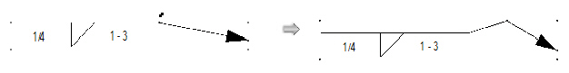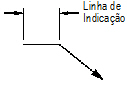
O produto Vectorworks Fundamentals provê um objeto linha de indicação básica. Na configuração do Vectorworks Design Series, a linha de indicação inclui parâmetros adicionais.
A ferramenta Linha de Indicação Simples insere uma linha de indicação básica. Dois modos são disponíveis.
Modo |
Descrição |
|---|---|
Restrito |
Limita a linha a ser vertical, horizontal, e 30 ou 45 da vertical ou horizontal em qualquer direção |
Livre |
Desenha a linha em qualquer angulo Pressione e segure a tecla Shift para orientar a linha a ângulos predeterminados |

Para inserir uma linha de indicação:
1. Clique o objeto Linha de Indicação Simples do conjunto Basico de ferramentas e selecione modo Restrito ou Livre da Barra de Ferramentas.
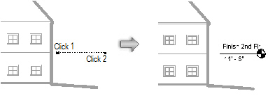
2. Clique e mova o mouse para definir o comprimento de ombro da linha de indicação. Clique e mova o mouse para definir a linha de indicação, e clique para ajustar o ponto final.
Uma vez que a linha de indicação foi colocada, seu marcador pode ser selecionado da paleta de Atributos (veja “Atributo de Marcadores” na página 1099).
 Inserindo
uma Linha de Indicação do Design Series
Inserindo
uma Linha de Indicação do Design Series
Para inserir um símbolo de linha de indicação no Vectorworks Desing Series:
Clique o objeto Linha de Indicação do conjunto de ferramentas Básico.
Se esta é a primeira vez que o objeto foi inserido nesta seção, a caixa de diálogo de Propriedades do Objeto abre. Escolha as propriedades padrão do objeto e clique OK. As propriedades podem ser editadas após colocadas através da paleta de Informações do Objeto.

Clique para mostrar/ocultar os parâmetros.
Uma vez que a linha de indicação foi colocada, seu marcador pode ser selecionado da paleta de Atributos.
Se houver vários objetos linhas de indicação, use o comando Alinhar/Distribuir Linhas de Indicação para melhorar a legibilidade.
~~~~~~~~~~~~~~~~~~~~~~~~~
Várias ferramentas no produto Vectorworks Fundamentals adiciona informação de conjunto a um desenho com objetos preformatados. O produto Vectorworks Design Series oferece ferramentas para objetos de anotações acicionais.
~~~~~~~~~~~~~~~~~~~~~~~~~
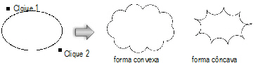
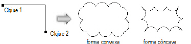
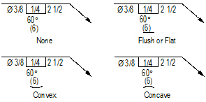
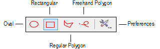
Use a ferramenta de Balões de Revisão para identificar uma seção do desenho que mudou. Insira um balão de revisão em uma área do desenho, ou ao redor de uma porção inteira do desenho, se apropriado.
Para os produtos Vectorworks Design Series, balões de revisão podem também ser criados primeiramente desenhando uma polilinha e então selecionando “Creating Objects from Shapes” na página 273).
Modo |
Descrição |
|---|---|
Oval |
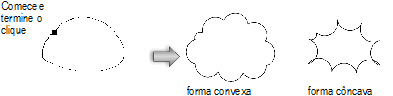
Insere o balão de revisão em volta do perímetro da oval prevista. Clique para ajustar o ponto inicial, mova o cursor na direção desejada, e clique para colocar o ponto final. Limite a oval a 45 graus para desenhar um círculo.
|
Retangular |
Insere o balão de revisão em volta do perímetro do retângulo previsto. Clique para ajustar o ponto inicial, mova o cursor na direção desejada, e clique para colocar o ponto final. Limite a oval a 45 graus para desenhar um quadrado.
|
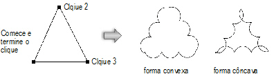
Polígono Regular |
Insere o balão de revisão ao redor do perímetro dos vértices especificados. Clique para posicionar o ponto de partida (primeiro vértice), clique na posição desejada para cada um dos vértices subsequentes, e ou clique no primeiro vértice para fechar o polígono ou faça um duplo clique no último vértice para criar um polígono aberto. Se o polígono for aberto, o balão de revisão será completado com base no contorno.
|
Polígono a Mão Livre |
Insere o balão de revisão ao redor do perímetro dos vértices especificados. Clique para posicionar o ponto inicial e clique-arraste para desenhar o polígono a mão livre. Se o polígono for aberto, o balão é completado com base no contorno.
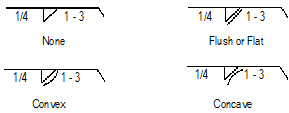
|

Para criar um balão de revisão:
1. Clique na ferramenta Balão de Revisão do conjunto de ferramentas Cotas/Anotações.
2. Clique o botão de Preferências na barra de Ferramentas para definir as propriedades do balão de revisão. As propriedades podem ser também ajustadas após colocação, a partir da paleta Informações do Objeto. Clique OK.
3. Selecione o modo balão de revisão e selecione para desenhar o balão com forma convexa ou côncava. A forma convexa desenha curvas para fora da imagem prevista ou dos vértices especificados. A forma côncava desenha curvas para dentro da imagem prevista ou dos vértices especificados.
4. Clique para desenhar o balão de revisão de acordo com o modo especificado.
Clique para mostrar/ocultar os parâmetros.
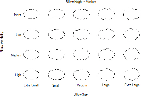
A ilustração seguinte demonstra o efeito de variar os parâmetros de tamanho e variação da curva.
~~~~~~~~~~~~~~~~~~~~~~~~~
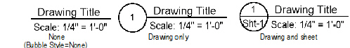
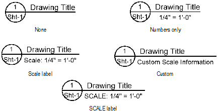
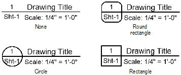
A ferramenta Rótulo do Desenho é um objeto pontual que fornece informação descritiva sobre o desenho.
De modo padrão, um objeto rótulo inclui um título, a escala do desenho, e um número designado automáticamente. O número da folha que contem o desenho pode também ser incluido no rótulo.
Muitos destes valores são padrões, dependendo de onde o rótulo foi criado: numa camada de projeto ou em uma anotação "viewport", por exemplo.

Para criar um rótulo do desenho:
1. Certifique-se que a camada apropriada está ativa.
2. Clique na ferramenta Rótulo do Desenho do conjunto de ferramentas Cotas/Anotações.
3. Clique no desenho na posição desejada para locar o objeto rótulo do desenho.
4. Clique novamente para ajustar a rotação.
Se esta for a primeira vez que o objeto é inserido nesta seção, a caixa de diálogo Propriedades do Objeto abre. Estes parâmetros se aplicam a colocações subsequentes do objeto e podem ser modificados na paleta Informações do Objeto. Clique OK.
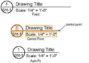
Desenhando objetos rótulo mantém um tamanho constante, independente da escala do desenho.
Clique para mostrar/ocultar os parâmetros.
5. Set the line attributes as needed using the Attributes palette.
~~~~~~~~~~~~~~~~~~~~~~~~~
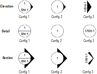
The Reference Marker tool displays the drawing number and sheet number of the referenced drawing. Select from a variety of configurations.

To create a reference marker:
1. Ensure that the appropriate layer is active.
2. Click the Reference Marker tool from the Dims/Notes tool set.
3. Click on the drawing at the desired location to place a reference marker object.
4. Click again to set the rotation.
If this is the first time the object is inserted in this session, the Object Properties dialog box opens. These parameters apply to subsequent placements of the object and can be changed in the Object Info palette. Click OK.
Reference marker objects maintain a constant size regardless of the drawing scale.
Click to show/hide the parameters.
5. Set the line attributes as needed using the Attributes palette.
~~~~~~~~~~~~~~~~~~~~~~~~~
The Data Stamp tool displays the date, time and file name of the current drawing. Select from a variety of configurations.

To create a data stamp:
1. Click the Data Stamp tool from the Dims/Notes tool set.
2. Click on the drawing at the desired location to place a data stamp.
If this is the first time the object is inserted in this session, the Object Properties dialog box opens. Specify the preferences to use for this tool during this session, and then click OK.
3. Click again to set the rotation.
The data stamp parameters can be edited from the Object Info palette.
Click to show/hide the parameters.
The date and time formats are determined by each Vectorworks application user’s local computer settings.
~~~~~~~~~~~~~~~~~~~~~~~~~
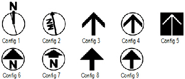
 North
Arrow
North
Arrow The North Arrow tool, available in the Vectorworks Design Series, indicates the drawing orientation; several different styles can be selected. The deviation from true magnetic north can be displayed on some of the configurations. If the design layer is georeferenced, the object is rotated to point in the proper direction.

To place a north arrow object:
1. Click the North Arrow tool from the Dims/Notes tool set.
2. Click on the drawing at the desired location to place a north arrow object.
3. Click again to set the rotation.
If this is the first time the object is inserted in this session, the Object Properties dialog box opens. These parameters apply to subsequent placements of the object and can be changed in the Object Info palette. Click OK.
North arrow objects maintain a constant size regardless of the drawing scale.
Click to show/hide the parameters.
~~~~~~~~~~~~~~~~~~~~~~~~~
 Revision
Marker
Revision
Marker The Revision Marker tool, available in the Vectorworks Architect and Landmark products, displays the drawing revision number.

To place a revision marker object:
1. Click the Revision Marker tool from the Dims/Notes tool set.
2. Click on the drawing at the desired location to place a revision marker object.
3. Click again to set the rotation.
If this is the first time the object is inserted in this session, the Object Properties dialog box opens. These parameters apply to subsequent placements of the object and can be changed in the Object Info palette. Click OK.
Revision marker objects maintain a constant size regardless of the drawing scale.
Click to show/hide the parameters.
~~~~~~~~~~~~~~~~~~~~~~~~~
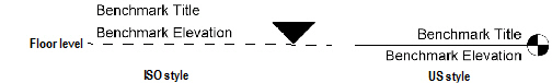
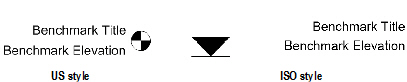
 Elevation
Benchmark
Elevation
Benchmark The Elevation Benchmark tool, available in the Vectorworks Architect and Landmark products, represents different levels in elevation drawings; two different elevation benchmark styles are available in the Vectorworks Architect and Landmark products: ISO and US.

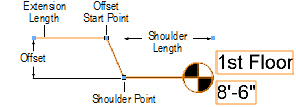
To place an elevation benchmark object:
1. Click the Elevation Benchmark tool from the Dims/Notes tool set.
2. Click on the drawing at the desired location to place an elevation benchmark linear object.
3. Click to set the length and rotation of the elevation benchmark.
If this is the first time the object is inserted in this session, the Object Properties dialog box opens. These parameters apply to subsequent placements of the object and can be changed in the Object Info palette. Click OK.
Click to show/hide the parameters.
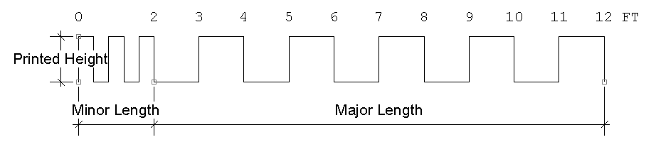
After creation, multiple elevation benchmark objects can be aligned and distributed with the Align/Distribute Leader Lines command; see “Alinhando e Distribuindo Linhas de Indicação” na página 1031.
~~~~~~~~~~~~~~~~~~~~~~~~~
 Indicating
the Slope of Surfaces
Indicating
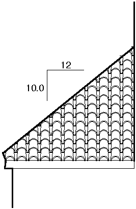
the Slope of Surfaces The Slope Dimension tool, available in the Vectorworks Architect and Landmark products, creates a rise over run indicator that displays the slope (rise/run) of any angle on any surface in the drawing.

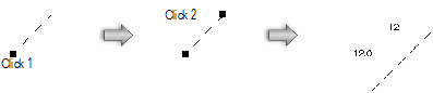
To create a slope indicator:
1. Click the Slope Dimension tool from the Dims/Notes tool set.
2. Click to mark the beginning of the slope. Click again to mark the end of the slope.
If this is the first time the tool is used in this session, the Slope Dimension Properties dialog box opens. Specify the preferences to use for this tool during this session, and then click OK. The preferences can be changed later in the Object Info palette.
3. The rise/run indicator is drawn.
Use the control point at the “elbow” of the slope indicator to move it; change the appearance of the rise/run indicator by editing its parameters in the Object Info palette.
Click to show/hide the parameters.
~~~~~~~~~~~~~~~~~~~~~~~~~
A scale bar can be placed on the drawing to define the scale of the drawing objects. To include a scale bar for a viewport, select Modify > Edit Viewport, and place the scale bar as a viewport annotation.

To add a scale bar to the drawing:
1. Click the Scale Bar tool from the Dims/Notes tool set.
2. Click on the drawing to insert the scale bar.
3. Click again to determine the rotation of the scale bar and to place it on the drawing.
4. Position the scale bar as desired. The scale bar properties can be edited later by selecting the scale bar and changing the properties in the Object Info palette.
Click to show/hide the parameters.
~~~~~~~~~~~~~~~~~~~~~~~~~
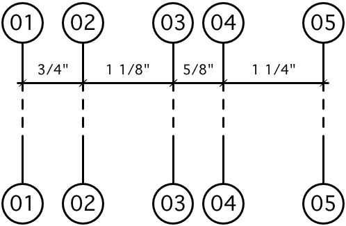
 Creating
Grid Bubbles
Creating
Grid BubblesGrid bubble objects, available in the Vectorworks Architect and Landmark products, are dimensioned grid lines with bubble markers. This type of drawing notation can help locate columns and other primary building features on construction documents.

To draw a grid bubble object:
1. Click the Grid Bubble tool from the Dims/Notes tool set.
Place a line of grid bubbles by drawing an open polygon with the tool. The first click starts the grid line; the second click determines the angle of the grid line and sets a marker at that location. Each remaining click sets a grid marker. Grid marker objects maintain a constant size regardless of the drawing scale.
2. Double-click to end the grid line. The first time the object is inserted in this session, the Preferences dialog box opens. These parameters apply to subsequent placements of the object and can be changed in the Object Info palette.
The grid bubble parameters can be edited in the Object Info palette.
Click to show/hide the parameters.
By combining several bubble grids and adjusting labeling properties, hierarchical (nested) grids can be created.
~~~~~~~~~~~~~~~~~~~~~~~~~
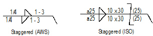
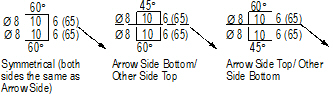
In some drawing standards, when drawing a building or object that is in complete symmetry, the designer may draw only half of the model and insert a symmetry label to indicate the symmetry line.

To insert a symmetry label:
1. Click the Symmetry Label tool from the Dims/Notes tool set.
2. Click on the drawing at the desired location to place the symmetry label.
3. Click to set the length and rotation of the label.
Symmetry label objects are specified and drawn in page scale; they draw to the same apparent size, regardless of the layer scale. If the layer the symmetry label object is on is re-scaled, or the symmetry label object is cut and pasted between layers of different scales, the symmetry label object automatically re-scales.
The symmetry label’s pen color, line weight, and line style can be changed in the Attributes palette.
~~~~~~~~~~~~~~~~~~~~~~~~~
 Error/Revision Management Using
Redlines
Error/Revision Management Using
RedlinesThe Redline tool and redline commands help control errors and revisions by providing the ability to annotate drawings with redlines and sketches, and to keep track of redline objects and any changes, corrections, and revisions that occur in a drawing.
The Redline tool and redline commands are compatible with redlines drawn in previous versions and will correctly handle both types of redlines.
~~~~~~~~~~~~~~~~~~~~~~~~~
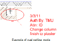
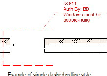
 Placing Redlines
 Use the Redline tool, available in the Vectorworks Design Series, to create redline objects, which are graphical time-stamped change requests on the drawing.
Several modes are available.

To redline an object or area:
1. Click the Redline tool from the Dims/Notes tool set, and select the desired drawing mode from the Tool bar.
2. Click Preferences from the Tool bar to specify the Redline tool parameters for this session.
For information on drawing freehand, ovals, polygons, and rectangles, see “Creating Shapes” on page 273.
3. Click OK. Draw the redline around the area to be revised or corrected.
Click to show/hide the parameters.
Based on the selected creation method, the appropriate tool creates the redline. This allows the use of SmartCursor cues, object snapping, and boomerang mode when drawing redlines.
Draw redlines on the design layer where the error occurred or where the desired revision is to be performed.
4. The Place Redline dialog box opens. Enter the redline information and authorization.
Click to show/hide the parameters.
5. Click OK.
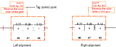
The redline object is drawn as specified, surrounding the drawing condition to be corrected. The date of the redline is automatically provided. Position redline text by clicking on the tag control point and dragging the tag to the desired location. If there are several redline objects, use the Align/Distribute Leader Lines command to improve readability (see “Alinhando e Distribuindo Linhas de Indicação” na página 1031).
The parameters of one or more selected redline objects can be edited in the Object Info palette.
Click to show/hide the parameters.
~~~~~~~~~~~~~~~~~~~~~~~~~
 Attaching
a Sketch to a Redline
Attaching
a Sketch to a RedlineIn screen plane mode, one or more selected objects can be attached to a redline object to illustrate the redline comments (Vectorworks Design Series required). The object to be attached as a sketch must be selected before drawing the redline; this process converts the selected object to a sketch symbol and places it in a Redline Sketches symbol folder saved with the file.

To attach a selected object as a redline sketch:
1. Switch to the screen plane (see “Planar Modes of 2D Objects: Screen Plane and Layer Plane” on page 148).
2. Select the object to be converted to a sketch.
3. Click the Redline tool from the Dims/Notes tool set, and draw the redline as described in “Placing Redlines” na página 1252.
The Place Redline dialog box opens.
4. Select Attach the current selection as a sketch and click OK.
5. The selection is converted to a symbol that is attached to and moves with the redline object.
The sketch can be hidden by deselecting Show Sketch in the Object Info palette.
~~~~~~~~~~~~~~~~~~~~~~~~~
 Show
or Hide Redlines
Show
or Hide Redlines Over the course of a project, most drawings receive a large number of redlines (Vectorworks Design Series required), which, if left visible, would clutter the drawing. Select Text > Redlines > Show or Hide Redlines to toggle redline visibility.
All Redline objects are drawn in the Redlines class. If redlines are hidden when a new redline is drawn, the Redlines class visibility is automatically turned on and all the redlines become visible. Use the Show or Hide Redlines command to hide them again.
~~~~~~~~~~~~~~~~~~~~~~~~~
 Pick
up Redline
Pick
up Redline Once the change or correction indicated by the redline has been resolved, the redline needs to be “picked up” or changed to a closed state (Vectorworks Design Series required).
To pick up a redline:
1. Select the redline object or objects.
2. Select Text > Redlines > Pick Up Redline.
Right-click on the redline and select Pick Up Redline from the context menu.
This sets the status of all selected redline objects to closed. The redline color changes from red to yellow, and the pick-up date is set.
Redlines can be picked up by selecting one or more redline objects and selecting Picked Up in the Object Info palette.
~~~~~~~~~~~~~~~~~~~~~~~~~
 Restore
Redline
Restore
Redline A selected closed redline object can be restored to an open status (Vectorworks Design Series required). A redline object may need to be restored when a revision has not been performed satisfactorily.
To change the state of a closed redline back to open:
1. Select the redline object or objects.
2. Select Text > Redlines > Restore Redline.
Right-click on the redline and select Restore Redline from the context menu.
The selected redlines are returned to an open status and the redline color changes back to red. The original redline creation date is displayed. Redlines can also be restored by selecting one or more redline objects and deselecting Picked Up in the Object Info palette.
~~~~~~~~~~~~~~~~~~~~~~~~~
 Redline
Status Worksheet
Redline
Status Worksheet The redline worksheet lists the status of all redlines in the current file (Vectorworks Design Series required). The Open Redlines section lists all redlines that require resolution; the Closed Redlines section shows all resolved redlines. For each redline item, the design layer location, date, and redline comment displays.
To create or open the redline status worksheet:
1. Select Text > Redlines > Create Redline Status WS.
2. The Redlines Status Report worksheet is created and opens automatically. It is added to the Window > Worksheets menu and it is listed in the Resource Browser.
Redlines, both open and closed, are listed in the report even if they are hidden in the current view of the file.
~~~~~~~~~~~~~~~~~~~~~~~~~
 Using
the ID Label Tool
Using
the ID Label Tool The ID Label tool, available in the Vectorworks Architect and Landmark products, labels drawing objects with an identifier so they can be properly referenced on an associated schedule. These labels can be applied to specific objects with attached data records, such as doors, windows, equipment, plumbing fixtures, electrical items, and irrigation objects. This tool also provides a convenient way to specify or edit attached record data. The ID labels can be customized using special symbols (see “Creating Custom ID Label Symbols” na página 1261 for more information).
For doors and windows, the ID label bubble size is independent of text size. The ID bubble is drawn at the size specified in the ID Label Size field of the Object Info palette, unless the text exceeds the ID bubble size; in this case, the bubble automatically expands to fit the text. To restore the ID bubble to a fixed size, reduce the text size to fit within the ID bubble.

To place an ID label:
1. Click the ID Label tool from the Dims/Notes tool set.
2. Click to set the location of the ID label.
3. Click on the object to associate with the ID label.
The ID/Specification Tool dialog box opens. Set the ID parameters.
4. Click Options to set specific preferences for this ID.
Click to show/hide the parameters.
If the object being labeled is a window or door, complete the fields in the ID Settings dialog box as described in the ID Tag tab section of “Window Settings: ID Tag Pane” on page 593 and “Door Settings: ID Tag Pane” na página 617. Select Auto-Increment ID Label in the ID Settings dialog box to automatically increment the numerical ID value each time the label is placed. Continue with step 6. For all other objects, go to step 5.
5. If the object being labeled is something other than a window or door, complete the fields in the Set ID Preferences dialog box.
Click to show/hide the parameters.
6. Click OK.
The ID label is drawn.
To bypass the ID Label dialog boxes and automatically place an existing ID label repeatedly, hold down the Alt (Windows) or Option (Mac) key while applying additional labels.
To easily convert any object into a door or window, place an ID label on the object and select the Window Object or Door Object ID Type in the ID/Specification Tool dialog box. A symbol is automatically created for the object and displays in the Resource Browser, and is available to use as symbol geometry for subsequently placed windows or doors. Select the window or door object and click Settings in the Object Info palette to open the Window or Door Settings dialog box to attach record information to include in the window or door Schedule (see “Inserting Windows in Vectorworks Design Series” on page 590 and “Inserindo Portas em Vectorworks Fundamentals” na página 607).
~~~~~~~~~~~~~~~~~~~~~~~~~
 Editing
Existing ID Labels and Record Information
Editing
Existing ID Labels and Record InformationAfter placement, objects with record information and ID labels (Vectorworks Architect or Landmark required) can be edited to change the record or ID data. Worksheets, including schedules, and the ID Label tool can change the record information of multiple objects at once.
Global changes to symbol and plug-in object record information can be made using database rows in worksheets created with the Vectorworks program. During a schedule review, it is often necessary to make changes to objects and update them automatically on the drawing.
Only database rows are directly associated with drawing elements, and can update the drawing in this way. Fields which result from a calculation, or from locked objects, workgroup-referenced items, or control points, cannot edit drawing elements. For more information on worksheets, see “Using Worksheets” on page 1315.
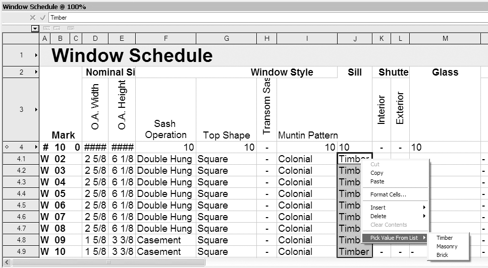
To edit record information from a worksheet:
1. Open the worksheet that contains the record information to be edited, by selecting the worksheet in the Resource Browser and selecting Edit from the Resources menu or the context menu. Alternatively, select the worksheet from the Window > Worksheets menu.
For example, a Window Schedule worksheet contains record information for the windows in the drawing.
2. Select the database row cell to be edited.
Text and number fields can be edited directly, while popup fields allow a selection to be made, either from the edit list at the top of the worksheet, or from the Pick Value from List context menu item.
To repeat the same value in several text or number fields of the same record, copy the desired value from one field, select multiple rows, and paste. (Pasting cannot be performed for popup fields.)
3. The drawing records automatically update with the new information, and the drawing objects reflect the changes.
If record field from a summarized database row has been edited, all objects referenced by the row are edited.
The ID Label tool can be used to change ID or record information after placing an ID. Labels and records for styled walls are edited differently; see “Editing ID Labels and Records for Wall Styles” na página 1260 for details.

To edit an existing ID label or record information:
1. Click the ID Label tool from the Dims/Notes tool set.
2. Double-click on the ID label to edit.
If the labeled object is a window or door, complete the fields as described in the Data tab section of “Window Settings: Data Pane” on page 602 and “Door Settings: Data Pane” na página 626. If editing the object through the Object Info palette, an additional parameter, ID Label Size, is available for controlling the size of the ID label bubble. Continue with step 4. For all other objects, go to step 3.
3. If the labeled object is something other than a window or door, edit the fields in the ID/Specification Tool dialog box, as described in “Using the ID Label Tool” na página 1257.
4. Click OK.
The edits are applied to the ID label and record attached to the object.
Data fields (including an ID label) are specified for each wall style, which means that each wall with a particular style has the same label and record attached to it. Therefore, ID labels and records cannot be edited for individual styled walls with the ID Label tool. (See “Using Wall Styles” on page 503 for more information about creating, editing, and using wall styles.)
To edit ID label or record information for a wall style:
1. Select the wall style from the Resource Browser and click Resources > Edit.
2. In the Edit Wall Style dialog box, click the Data Fields tab.
3. Enter a label ID in the Mark field, and enter other data fields as necessary.
4. Click OK to close the Edit Wall Style dialog box, and click OK again to close the Wall Replacement dialog box.
From this point forward, walls that are created with this style have the specified data record attached; when an ID label is added to a wall that has this style, the Mark entry displays in the label.
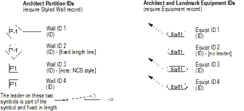
 Vectorworks
Architect and Landmark ID Symbols
Vectorworks
Architect and Landmark ID Symbols The following ID symbols are provided with the Vectorworks Architect and Landmark products, and require the presence of the indicated record format in the drawing file. The ID Label tool creates the record format if it does not already exist.
~~~~~~~~~~~~~~~~~~~~~~~~~
 Creating
Custom ID Label Symbols
Creating
Custom ID Label SymbolsThe Vectorworks Architect and Landmark ID labels are created as plug-in objects that draw an ID symbol and an optional leader line. The symbols can automatically be kept horizontal, or can be rotated to the leader line angle.
It is possible to create ID symbols based on custom markers. ID symbols have certain requirements that must be met.
The ID Label tool (see “Using the ID Label Tool” na página 1257) detects the presence of any existing record information for the object being labeled in the drawing; if the tool cannot detect record information, you are prompted to select the appropriate record from a list. The ID symbols defined to work with that record type display for selection.
The ID Label tool determines whether the ID symbol requested in the dialog box is present in the drawing. If not, it copies it in from the ID_Symbols.vwx file, and scales it to the current drawing layer scale. Once an appropriate scaled symbol is created, it is used without further reference to external documents.
ID symbols must meet the following requirements:
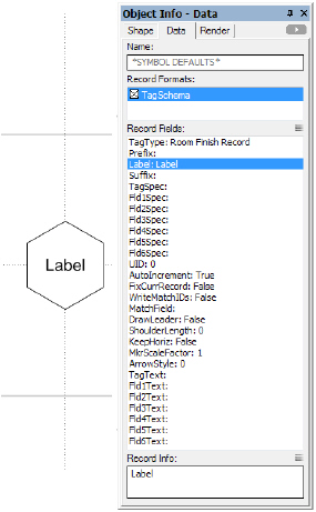
• They are stored in the library file [Vectorworks]\Plug-Ins\Common\Data\ID_Symbols.vwx;
• They are created at a 1:1 scale, using certain graphic primitives;
• They use linked text to display ID and attribute information; and,
• They have a TagSchema record attached.
The TagSchema record determines the behavior of the ID symbol text. This record is present in the ID_Symbols.vwx file.
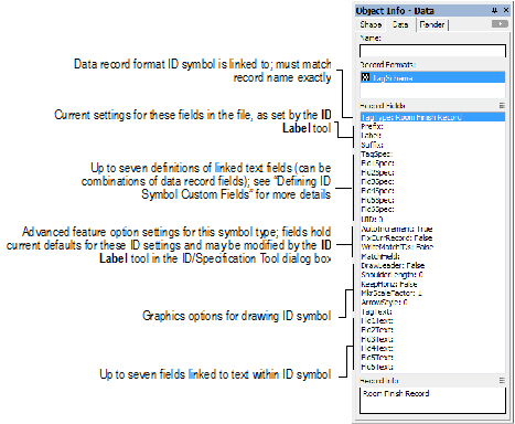
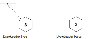
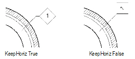
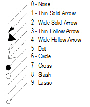
The AutoIncrement, FixCurrRecord, WriteMatchIDs, DrawLeader, and KeepHoriz fields are Boolean (true/false) values; ShoulderLength and MkrScaleFactor are numerical values. All other fields are text values.
Four TagSchema record fields determine whether the ID symbol is drawn with a leader, and, if so, determine the leader’s appearance.
Click to show/hide the parameters.
There are three ID record writing options controlled by four fields in the TagSchema record:
Click to show/hide the parameters.
The ID symbol can have up to seven fields containing virtually any text, combined with the contents of the data record the ID uses.
For example, the ID Label tool reads the contents of the Fld1Spec field and writes the results to the Fld1Text field. The “Spec” field follows the format FieldName& “string constant” where the field names are fields in the data record named in the TagType field; the & indicates a concatenation, and the string constants are surrounded by double quotes.
For example, a field in the data record is called “Count.” This is a number field representing the total number of something. You want the first field in the ID to read: TOTAL: 12 when “Count” is 12. Enter the following formula in the Tag1Spec field: “TOTAL: ”&Count. There are no spaces between the ampersand and the field name, or between the string constant (in quotes) and the ampersand.
You can concatenate any number of fields and constants. For example, you could add the word “Item(s)” to the tag field definition by using the following formula: “TOTAL: ”&Count& “ Item(s)”.
There are a variety of pre-defined fields in the ID symbols that come with the Vectorworks Architect and Landmark products. Use these as a guideline in understanding this special formula language. This same formula convention is also used to define HVAC object tags.
If the ID Label tool cannot find the data record specified in the TagType field of the TagSchema record, the error message #RECORDNAME?# displays when the ID is placed. If any of the fields in the formula are misnamed, the message #FIELDNAME?# displays in the affected ID field. Verify the spelling of record and field names and ensure the data record is defined as described in “The Data Record” na página 1264.
The data record named in the TagType field of the ID symbol should be part of the standard records created using the VA Records and Schedules command and should be present in the current preference set. This enables the ID Label tool to create the record automatically if it is not defined at the time the ID Label tool is used.
The TagType “Styled Wall” is reserved for use when an ID is placed on a styled wall.
~~~~~~~~~~~~~~~~~~~~~~~~~
 Creating
Custom ID Symbols
Creating
Custom ID SymbolsKeeping in mind the information described in “Understanding ID Labels” na página 1261, it is possible to create a custom ID symbol to be used by the ID Label tool (Vectorworks Architect or Landmark required).
An ID symbol can consist of any 2D object supported in the Vectorworks program except circles, arcs, grouped objects, or other symbols. These guidelines are necessary for the scaling algorithm currently used by the ID Label tool, to scale the symbol to the correct scale for the file. To achieve the look of an arc in the symbol, use an arc-smoothed vertex of a polyline; use an oval instead of a circle.
To create a custom ID symbol:
1. Open the ID Symbols.vwx file, located in the [Vectorworks]\Plug-Ins\Common\Data folder.
The TagSchema record, as well as the ID symbols currently used by the ID Label tool, are present in this file.
2. At a 1:1 scale, draw the object representing the ID symbol.
3. Select Modify > Create Symbol to create a symbol from the object (see “Creating New Symbols” on page 235 for more information on creating symbols).
4. Select the new symbol in the Resource Browser and select Resources > Edit.
The Edit Symbol dialog box opens.
5. Select the 2D Component and click Edit to open the Edit Symbol window.
6. Deselect all items by clicking in an empty area.
On the Data tab of the Object Info palette, *SYMBOL DEFAULTS* is displayed.
7. Attach the Tag Schema record by selecting it from the Data tab.
8. An “X “displays in the check box.
9. Select the TagType field and replace the field name with the exact name of your custom record.
10. Create and format text to be used to display the ID symbol text.
For more information, see “Linking Text to Record Formats” on page 265.
11. With the text selected, select Tools > Records > Link Text to Record.
The Choose Field dialog box opens.
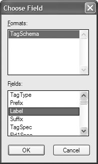
12. In the Tag Schema record format, select the Label field and click OK.
13. The symbol text is linked to display the contents of the Label record field.
To check the text link, enter text in the Label field on the Data tab of the Object Info palette. Data entered now would be overwritten later, in any case, by the ID Label tool.
14. Click Exit Symbol at the top right corner of the window to return to the drawing.
15. In the Pally script palette, double-click the Output ID Prefs script to run it.
16. Save the ID_Symbols.vwx file.
17. In the drawing file where the custom ID symbol is to be used by the ID Label tool, ensure that a record format exists which exactly matches the record name entered previously in the TagType field.
18. Select the ID Label tool from the Dims/Notes tool set.
The ID/Specification Tool dialog box opens.
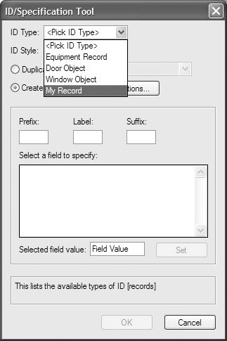
19. The custom record is one of the selections for ID Type. Select it to use the associated custom ID symbol and click OK.
 Section
Note
Section
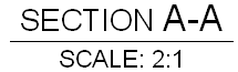
Note The Section Note object, available in the Vectorworks Design Series, annotates the drawing or detail with section letters, and, if desired, a scale. The text attributes are editable by the Format Text command.

To insert a section note:
1. Click the Section Note tool from the Dims/Notes tool set.
2. Click to place the object in the drawing, and click again to set the object’s rotation. If this is the first time the object is placed in the drawing, an object properties dialog box opens. These parameters apply to subsequently created objects; they can be changed later by accessing them from the Object Info palette.
3. Specify the object properties and click OK.
Click to show/hide the parameters.
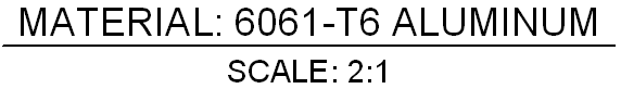
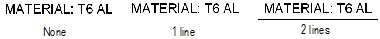
 Material Note
 The Material Note object, available in the Vectorworks Design Series, annotates the drawing or detail with material composition, and, if desired, scale. The text attributes are editable by the Format Text command.

To insert a material note:
1. Click the Material Note tool from the Dims/Notes tool set.
2. Click to place the object in the drawing, and click again to set the object’s rotation. If this is the first time the object is placed in the drawing, an object properties dialog box opens. These parameters apply to subsequently created objects; they can be changed later by accessing them from the Object Info palette.
3. Specify the object properties and click OK.
Click to show/hide the parameters.
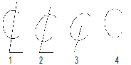
 Center
Line Marker
Center
Line Marker The Center Line Marker object, available in the Vectorworks Design Series, denotes the center line on drawings.

To insert a center line marker object:
1. Click the Center Line Marker tool from the Dims/Notes tool set.
2. Click to place the object in the drawing, and click again to set the object’s rotation. If this is the first time the object is placed in the drawing, an object properties dialog box opens. These parameters apply to subsequently created objects; they can be changed later by accessing them from the Object Info palette.
3. Specify the object properties and click OK.
Click to show/hide the parameters.
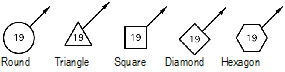
 Creating
Detail Bubbles
Creating
Detail BubblesA detail bubble, available in the Vectorworks Design Series, assigns a detail number to the parts of an assembly drawing.
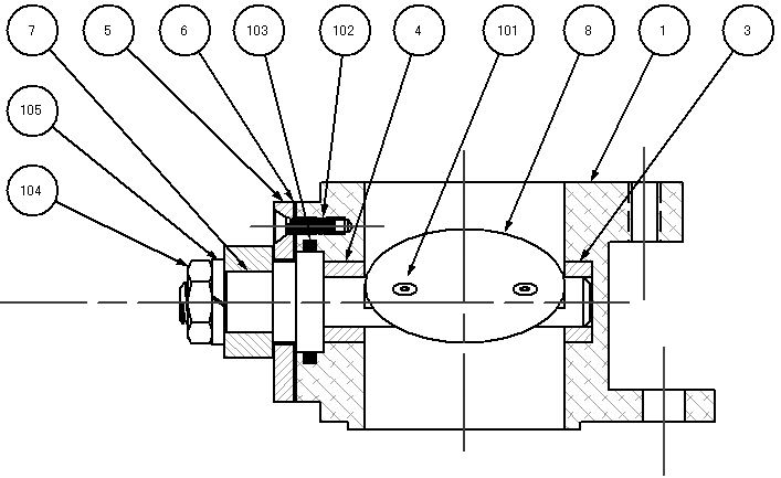
The information associated with the detail bubble can be used to create both parts lists and bill of materials lists.
~~~~~~~~~~~~~~~~~~~~~~~~~
 Adding
Detail Bubbles
Adding
Detail Bubbles 
To add a detail bubble (Vectorworks Design Series required):
1. Click the Detail Bubble tool from the Dims/Notes tool set.
2. Click on the drawing to place the bubble portion of the object. Click again to place the marker.
If this is the first time the object has been inserted in this session, the Object Properties dialog box opens. If the Attributes palette has not been set to use end markers, select the marker style, size, and angle from the Object Properties dialog box.
If no Part Info record exists, one is created automatically the first time a detail bubble is placed in the drawing.
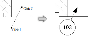
The detail bubble number automatically increments as the bubbles are placed. Change the auto-incrementing number by editing the Item Number field in the Object Info palette. When detail bubble placement resumes, the last number entered becomes the starting number.
~~~~~~~~~~~~~~~~~~~~~~~~~
 Detail
Bubble Record Format
Detail
Bubble Record FormatThe Part Info record format stores the information for the detail bubble (Vectorworks Design Series required). This record format can be edited to add new fields or to delete existing fields. To edit the record format, right-click on the record format in the Resource Browser and select Edit. For more information on record formats, see “Record Formats” on page 258.
If new fields are created, the existing Bill of Materials and Parts List worksheets need to be modified to reflect the changes. Alternatively, create new worksheets to accommodate the new fields. For more information on using worksheets, see “Using Worksheets” on page 1315.
~~~~~~~~~~~~~~~~~~~~~~~~~
 Editing
Detail Bubbles
Editing
Detail BubblesEdit the detail bubble properties (Vectorworks Design Series required) in the Object Info palette.
Click to show/hide the parameters.
Once the detail bubble has been placed, its marker can be selected from the Attributes palette (see “Atributo de Marcadores” na página 1099).
To edit the record information associated with a detail bubble:
1. Select the bubble, and then click Change Bubble Info on the Object Info palette.
The Edit Detail Bubble dialog box opens.
2. Enter the information associated with the detail bubble. The information can be used to complete the parts list and bill of materials worksheets.
3. Click OK to return to the Object Info palette. If the Item # was changed, the change is automatically made to the Object Info palette and the object.
~~~~~~~~~~~~~~~~~~~~~~~~~
 Creating
a Bill of Materials
Creating
a Bill of Materials The information associated with the detail bubbles (Vectorworks Design Series required) can be included in a worksheet which automatically generates a bill of materials list.
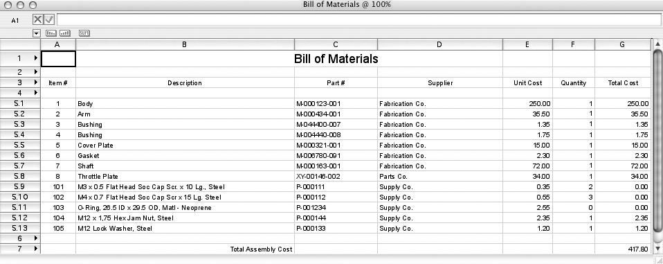
To create a bill of materials:
1. Once the detail bubble record information has been completed, select the Create Bill of Materials command from the appropriate menu:
• Architect: AEC > Machine Design > Create Bill of Materials
• Landmark: Landmark > Machine Design > Create Bill of Materials
• Spotlight: Spotlight > Machine Design > Create Bill of Materials
2. With the bull’s-eye cursor, click in the drawing to place the worksheet.
Alternatively, access the Bill of Materials worksheet object with the Resource Browser from the title blocks file in the [Vectorworks]\Libraries folder (see “Bibliotecas de Recursos” na página 215). Double-click the Bill of Materials worksheet object in the Resource Browser to place the worksheet graphic object.
3. Double-click on the worksheet, or select Window > Worksheets > Bill of Materials, to open the worksheet. From the Worksheet menu, select Recalculate. The record information from the detail bubbles automatically fills the worksheet, and all calculations are performed. For more information on worksheets, see “Using Worksheets” on page 1315.
4. Close the worksheet. The worksheet graphic object on the drawing reflects the changes.
5. Reopen the worksheet and select Recalculate from the Worksheet menu to update the worksheet when any changes are made to the record information.
A parts list can be added to an ASME title block; see “Sheet Border Properties” on page 76.
~~~~~~~~~~~~~~~~~~~~~~~~~
 Creating a
Parts List
Creating a
Parts List The information associated with the detail bubbles can be included in a worksheet that automatically generates a parts list (Vectorworks Design Series required).
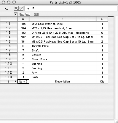
To create a parts list:
1. Once the detail bubble record information has been completed, select the Create Parts List command from the appropriate menu:
• Architect: AEC > Machine Design > Create Parts List
• Landmark: Landmark > Machine Design > Create Parts List
• Spotlight: Spotlight > Machine Design > Create Parts List
2. With the bull’s-eye cursor, click in the drawing to place a Parts List worksheet.
Alternatively, select the appropriate parts list worksheet object with the Resource Browser from the title blocks file in the [Vectorworks]\Libraries folder (see “Bibliotecas de Recursos” na página 215). Double-click the appropriate parts list worksheet object in the Resource Browser to place the worksheet graphic object.
The Parts List-1 worksheet object is formatted to fit the ASME title blocks for ASME A, B, and C and ISO A2, A3, A4, and A5 drawing sizes. The Parts List-2 worksheet object is formatted to fit the ASME title blocks for ASME D, E, and F, and ISO A0 and A1 drawing sizes.
3. Double-click on the worksheet, or select Window > Worksheets > Parts List to open the worksheet. From the Worksheet menu, select Recalculate. The record information from the detail bubbles automatically fills the worksheet, and all calculations are performed. For more information on worksheets, see “Using Worksheets” on page 1315.
4. Close the worksheet. The worksheet graphic object on the drawing reflects the changes.
5. Reopen the worksheet and select Recalculate from the Worksheet menu to update the worksheet when any changes are made to the record information.
~~~~~~~~~~~~~~~~~~~~~~~~~
 Welding
and Surface Texture Symbols
Welding
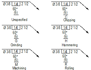
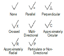
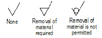
and Surface Texture SymbolsVectorworks Design Series products contain a comprehensive collection of welding symbols and also include a surface texture symbol. All symbols are placed as point objects.
~~~~~~~~~~~~~~~~~~~~~~~~~
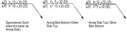
 Fillet
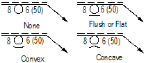
Welding Symbol
Fillet
Welding Symbol
To insert a fillet welding symbol (Vectorworks Design Series required):
1. Click the Welding Sym-Fillet tool from the Dims/Notes tool set.
2. Click to place the object in the drawing, and click again to set the object’s rotation. If this is the first time the object is placed in the drawing, an object properties dialog box opens. These parameters apply to subsequently created objects; they can be changed later by accessing them from the Object Info palette.
3. Specify the object properties and click OK.
4. Once the object has been placed, its marker can be selected from the Attributes palette (see “Atributo de Marcadores” na página 1099).
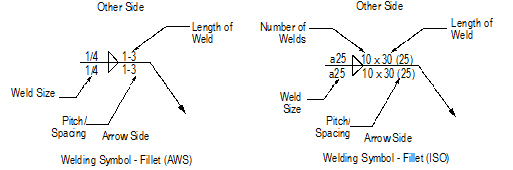
Click to show/hide the parameters.
~~~~~~~~~~~~~~~~~~~~~~~~~
 Groove
Welding Symbol
Groove
Welding Symbol 
To insert a groove welding symbol (Vectorworks Design Series required):
1. Click the Welding Sym-Groove tool from the Dims/Notes tool set.
2. Click to place the object in the drawing, and click again to set the object’s rotation. If this is the first time the object is placed in the drawing, an object properties dialog box opens. These parameters apply to subsequently created objects; they can be changed later by accessing them from the Object Info palette.
3. Specify the object properties and click OK.
4. Once the object has been placed, its marker can be selected from the Attributes palette (see “Atributo de Marcadores” na página 1099).
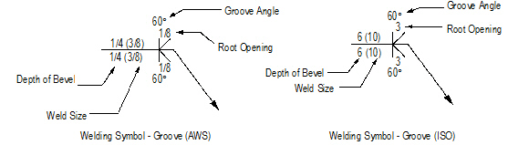
Click to show/hide the parameters.
~~~~~~~~~~~~~~~~~~~~~~~~~
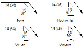
 Flange
Welding Symbol
Flange
Welding Symbol 
To insert a flange welding symbol (Vectorworks Design Series required):
1. Click the Welding Sym-Flange tool from the Dims/Notes tool set.
2. Click to place the object in the drawing, and click again to set the object’s rotation. If this is the first time the object is placed in the drawing, an object properties dialog box opens. These parameters apply to subsequently created objects; they can be changed later by accessing them from the Object Info palette.
3. Specify the object properties and click OK.
4. Once the object has been placed, its marker can be selected from the Attributes palette (see “Atributo de Marcadores” na página 1099).
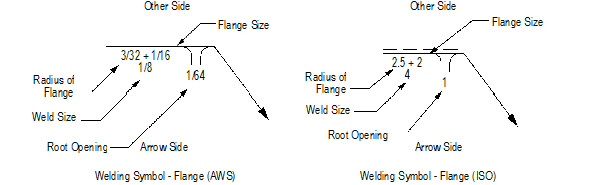
Click to show/hide the parameters.
~~~~~~~~~~~~~~~~~~~~~~~~~
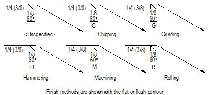
 Miscellaneous
Welding Symbols
Miscellaneous
Welding Symbols 
To insert a miscellaneous welding symbol (Vectorworks Design Series required):
1. Click the Welding Sym-Misc tool from the Dims/Notes tool set to insert a spot, seam, stud, or surfacing welding symbol.
2. Click to place the object in the drawing, and click again to set the object’s rotation. If this is the first time the object is placed in the drawing, an object properties dialog box opens. These parameters apply to subsequently created objects; they can be changed later by accessing them from the Object Info palette.
3. Specify the object properties and click OK.
4. Once the object has been placed, its marker can be selected from the Attributes palette (see “Atributo de Marcadores” na página 1099).
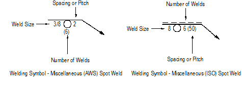
Click to show/hide the parameters.
~~~~~~~~~~~~~~~~~~~~~~~~~
 Slot-Plug
Welding Symbol
Slot-Plug
Welding Symbol 
To insert a slot-plug welding symbol (Vectorworks Design Series required):
1. Click the Welding Sym-Slot-Plug tool from the Dims/Notes tool set.
2. Click to place the object in the drawing, and click again to set the object’s rotation. If this is the first time the object is placed in the drawing, an object properties dialog box opens. These parameters apply to subsequently created objects; they can be changed later by accessing them from the Object Info palette.
3. Specify the object properties and click OK.
4. Once the object has been placed, its marker can be selected from the Attributes palette (see “Atributo de Marcadores” na página 1099).
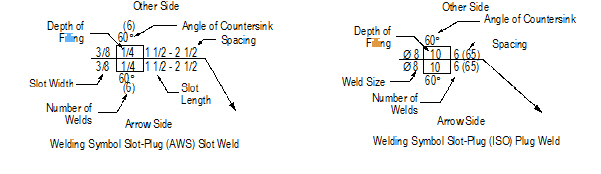
Click to show/hide the parameters.
~~~~~~~~~~~~~~~~~~~~~~~~~
 Surface
Texture Symbol
Surface
Texture Symbol
To insert a surface texture symbol (Vectorworks Design Series required):
1. Click the Surface Texture Symbol tool from the Dims/Notes tool set.
2. Click to place the object in the drawing, and click again to set the object’s rotation. If this is the first time the object is placed in the drawing, an object properties dialog box opens. These parameters apply to subsequently created objects; they can be changed later by accessing them from the Object Info palette.
3. Specify the object properties and click OK.
Click to show/hide the parameters.
~~~~~~~~~~~~~~~~~~~~~~~~~
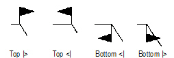
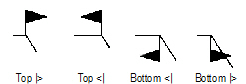
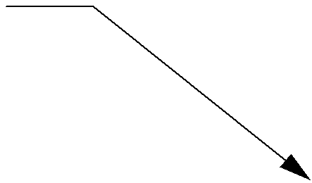
 Editing the
Arrow Segment
Editing the
Arrow Segment The arrow segment of each Vectorworks Design Series welding symbol has two control points for adjusting the segment position.
To move the control points of an arrow segment:
1. Select the welding symbol to edit.
2. Click and hold the leader end control point.
3. Drag the leader end control point to the new location and click to set.
4. Click and hold the leader shoulder control point.
5. Drag the leader shoulder control point to the new location and click to set.