Antes de iniciar um novo desenho, você deverá determinar as propriedades como escala, configuração de cores, vistas e cotas. Veja “Opções de Layout de Paletas” na página 37 para conhecer mais sobre as opções da janela de preferências antes de configurar o desenho.
A combinação de camadas, classes e vistas pode produzir uma grande variedade de diferentes desenhos a partir do mesmo documento (veja“Organizando Seu Desenho” na página 151). A configuração apropriada do documento irá garantir uma maior flexibilidade do mesmo para gerar diferentes saídas.
Três configurações fundamentais de um desenho do Vectorworks são: Escala da Camada, Unidades e tamanho do desenho. Uma vez que estas configurações tenham sido estabelecidas, algumas definições opcionais de desenho podem ser encontradas nas Preferências do Documento, Scripts, Grades de Atração e Referência,Camadas e Classes, entre outras configurações default; apesar destes ajustes não serem obrigatórios, são bastante recomendados.
É recomendável definir as camadas e as classes durante a configuração do desenho. Veja “Administrando Camadas” na página 156 e “Classes” na página 171 para maiores informações sobre como criar camadas e classes.
Quando estiver usando gabaritos, muitos destes ajustes já estarão definidos.
~~~~~~~~~~~~~~~~~~~~~~~~~
A escala da camada indica a proporção entre o tamanho real de um objeto e o seu tamanho no desenho. A escala da camada existe para permitir que as propriedades gráficas de um desenho ou de um modelo sejam representadas corretamente, como se você estivesse desenhando em uma certa escala num pedaço de papel. Por exemplo, na escala de camada padrão de 1:1, cada polegada no desenho corresponde a uma polegada no “mundo real”. A escala permite representar corretamente atributos como espessura da linha, estilo da linha (comprimento do tracejado), tamanho do marcador, tamanho do texto e hachuras.
No modo “O Que Você Vê é o Que Você Tem” (WYSIWYG), a escala é necessária para exibir estes atributos corretamente; isto permite que você visualize o desenho da forma como ele realmente será. Defina a escala da camada com o mesmo valor da escala de saída predominante no projeto. Assim, a menor quantidade possível de escala de atributos será usada nas viewports.
O Vectorworks pode usar uma escala para todas as camadas de projeto no arquivo, ou uma escala diferente para cada camada de projeto.
Para mudar a escala da camada atual ou para mudar a escala de todo o desenho:
1.Acesse o menu contextual do documento clicando com o botão direito (Windows) ou Ctrl-Clique (Macintosh) na área de desenho e selecione Escala da Camada Ativa. Você também pode clicar no botão Escala da Camada se a escala estiver sendo exibida na barra de visualização.
A janela Escala da Camada irá aparecer.
2.Você pode tanto selecionar uma escala padrão existente como criar a sua própria, digitando o valor desejado no campo Escala Papel.
3.Para mudar a escala para todo o desenho, em todas as camadas, selecione a opção Todas as Camadas.
4.Se desejar que seu texto seja escalado proporcionalmente ao resto do desenho, assinale a opção Escalar Texto. Se você não selecionar esta opção, seu texto irá permanecer no tamanho original enquanto os objetos ao seu redor serão escalados.
5. Clique OK.
Para mudar a escala de uma ou mais camadas individualmente:
1.Selecione Organizar > Organização.
A janela de diálogo Organização aparecerá. Clique na aba Camada de Projeto.
2.Selecione a Camada que você deseja alterar na lista de Camadas de Projeto e clique em Editar (ou clique duas vezes no nome da camada).
A janela Editar Camada de Projeto irá se abrir (veja “Definindo Propriedades da Camada de Projeto” na página 160).
3.Clique no botão Escala.
A janela de diálogo de Escala da Camada abrirá.
4.Selecione uma das escalas, ou crie uma escala personalizada (digitando o valor em Escala Papel).
5.Para que o texto seja escalado apropriadamente de acordo com o resto do desenho selecione a opção Escalar Texto. Deselecione esta opção para que o texto não seja afetado pela mudança de escala.
6.Certifique-se de que a opção Todas as Camadas não está selecionada.
7. Clique OK.
~~~~~~~~~~~~~~~~~~~~~~~~~
O Vectorworks permite a você escolher uma ampla variedade de sistemas métricos, incluindo milímetros, centímetros, metros, pés, polegadas ou uma combinação dessas unidades. Além disso, o programa oferece a flexibilidade de criar seus próprios sistemas de medida personalizados. Seja qual for o sistema de medida escolhido, o Vectorworks o aplica globalmente em todo seu desenho, desde as medidas apresentadas na régua (nas laterais da janela) até aquelas usadas nas cotas e planilhas.
O comando Unidades abre a janela Unidades, que organiza as configurações de unidades em duas abas:
• As opções da aba Cotas e Visualização Gerais afetam as unidades de medida usadas no desenho e as opções de arredondamento em cotas primárias.
• A aba Cotas Duplas contém vários parâmetros encontrados na aba Cotas e Visualização Gerais mas estas opções se aplicam somente às cotas secundárias. Se cotas duais não estiverem sendo usadas, estas configurações não terão efeito. Para maiores informações sobre cotas duais, veja “Cotas Duais” on page 1195.
Para selecionar ou modificar o sistema de unidades:
1.Selecione Arquivo > Ajustes do Documento > Unidades.
A janela de diálogo Unidades aparecerá.
2. Defina os parâmetros de visualização da unidade, e então clique OK.
Clique para mostrar / ocultar os parâmetros.
Para criar um sistema de medidas personalizado:
1.Selecione Arquivos > Ajustes do Documento > Unidades.
A caixa de diálogo Unidades abrirá.
2.Selecione Personalizar a partir do menu de Unidades de comprimento, área ou volume, ou se estiver editando um sistema de medidas personalizado, selecione o nome Personalizado a partir do menu Unidades.
3.Clique Personalizar.
A janela Unidades Personalizadas: Comprimento, Unidades Personalizadas: Área ou Unidades Personalizadas: Volume irá se abrir, dependendo do tipo de unidade a ser criada ou editada. Os valores disponíveis em cada campo variam baseados no tipo de unidade personalizada.
Clique para mostrar / ocultar os parâmetros.
4.Clique OK para sair da janela de Unidades Personalizadas.
5. Entre com os outros critérios da unidade como já descrito anteriormente em “Unidades” na página 66.
6. Clique OK.
Existem dois sistemas de grades separados para denhar com precisão: o Guia de Atração e o Guia de Referências.

A Grade de Atração é uma grade invisível que o Vectorworks usa para auxiliar no desenho e posicionamento preciso de objetos. Conforme você arrasta o cursor pela tela, esta grade (quando ativada na Paleta de Atrações) irá limitar o movimento do cursor fazendo com que ele "grude" em cada incremento da Grade de Atração. Por exemplo, enquanto você estiver posicionando um objeto no desenho, seu contorno irá ser atraído forçosamente para a grade de atração.
Através de teclas de atalho você pode fazer com que os objetos sejam atraídos à grade. Veja “Aba Edição” na página 47 fpara maiores informações.
A Grade de Referência, normalmente aparece na tela (dependendo da quantidade de zoom e dimendões da grade), e pode ser impressa. A maneira mais prática de usar a grade de Referência é como se ela fosse uma extensão para a grade de atração.
Dependendo do que está sendo desenhado, você pode desejar ou não que estas duas grade sejam idênticas. Se você estiver desenhando gabinetes de cozinha com uma tolerância de 1 mm, faria sentido ajustar a Grade de Atração para 1mm. Entretanto, será difícil desenhar em uma tela exibindo 10 linhas verticais e horizontais espremidas em cada centímetro.
Na configuração do arquivo, permite escolher as opções de alinhamento e grade de referência de acordo com a escala do desenho. Veja “Atrair à Grade” na página 129. A cor da grade de referência pode ser alterada. Veja “Configurando as Dicas Interativas de Tela” na página 112.
~~~~~~~~~~~~~~~~~~~~~~~~~
O comando Criar Guias lhe oferece a possibilidade de desenhar linhas guias que você poderá usar para atrair objetos visualmente a elas. O Vectorworks permite criar guias de qualquer formato e tamanho. Além de servir como uma referência visual, as guias também respondem ao SmartCursor do Vectorworks e às definições na Paleta de Atrações para certificar que sua atração a elas esteja 100% preciso. Guias são objetos que o Vectorworks trava em uma classe com uma cor diferenciada. As guias são usadas para auxiliar o desenho na tela. As Guias são sempre impressas a menos que o comando Esconder Guias esteja selecionado ou o comando Apagar Todas as guias tenha permanentemente apagado as guias.
Para criar uma Guia:
1.Crie o objeto que você deseja transformar em guia.
2.Selecione este objeto.
3.Selecione Modificar > Guias > Criar Guia.
O Vectorworks transformará o objeto em uma guia.
No submenu Guias, você também encontrará as seguintes opções.
Opções |
Descrição |
|---|---|
Criar Guias |
O objeto selecionado é convertido em guia. |
Selecionar Guias |
Seleciona todas as guias no seu desenho. |
Mostrar Guias |
Mostra todas as guias do desenho caso estejam escondidas. |
Esconder Guias |
Esconde temporariamente as guias do desenho. |
Apagar Todas as Guias |
Remove permanentemente as guias do desenho. |
Você pode atrair objetos às guias utilizando a opção de restrição de Atrair ao Objeto (na Paleta de Atrações). A distância que cada objeto se atrai à grade é determinado pelo ajuste do Raio de Atração nas preferências do Vectorworks. Veja “Aba Interatividade” na página 53 para detalhes nos ajustes do Raio de Atração.
Para remover uma única guia, selecione-a e use o comando Modificar > Destravar. A guia passará a ficar então editável. Selecione Editar> Apagar (ou tecle Delete) para removê-la do desenho. Use esta mesma técnica também para mover a guia pelo desenho. Selecione Modificar > Travar uma vez que a guia esteja realocada na posição desejada.
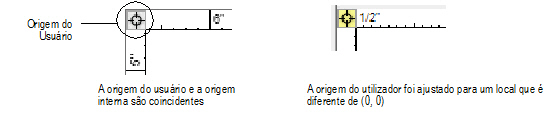
O centro de um desenho Vectorworks tem coordenadas em (0;0). Essa localização chama-se origem interna. Há também a origem do usuário. As coordenadas dos desenhos são mostradas em relação à origem do usuário. Normalmente a origem interna, a origem do usuário e o centro da página coincidem.
Dependendo das necessidades do projeto, e para alguns arquivos importados (para manter suas coordenadas), a origem do usuário precisa ser deslocada para que fique diferente da localização da origem interna. Uma razão para mudar a origem é para tornar mais fácil o trabalho com valores de coordenadas, medidas e distâncias. Por exemplo, os suíços usam um sistema de pontos de referência para medidas arquitetônicas no qual tudo é relativo a um ponto na Europa. Quando um prédio está localizado em certo lugar, este lugar é referenciado de forma a ter uma determinada distância e direção desse ponto. Usar esse sistema cria grandes números nas réguas e na paleta de Informações de Objeto. Na caixa de diálogo Origem do Usuário, você pode alternar entre a origem do usuário (o local do prédio) e a origem interna (o ponto de referência).
Mudar a origem do usuário pode ter grandes consequências. Tenha cuidado ao modificá-la.
Muitos comandos relacionados à origem do usuário e à origem interna estão disponíveis no programa Vectorworks.
~~~~~~~~~~~~~~~~~~~~~~~~~
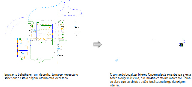
Em alguns desenhos, os objetos podem estar localizados a vários quilômetros ou milhas de distância entre si e/ou entre eles e a origem interna. Para referência, é fácil mudar a visualização para localizar a origem interna com o comando Localizar Origem Interna.
Para localizar a origem interna relativa a objetos visíveis:
1. Selecione Organizar > Origem > Localizar Origem Interna.
2. A vista do desenho será alterada. Ela mudará para a visualização Topo/Planta, se necessário, e a visualzação ficará centralizada na origem interna. O fator de zoom será ajustado de forma que os objetos visíveis no momento permaneçam na tela relativa à origem interna. Se o marcador da origem interna houver sido configurado para ser exibido nas preferências do Vectorworks, ele será automaticamente ligado.
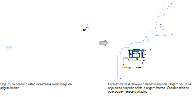
Se os objetos estiverem muito distantes da origem interna, use Centralizar Desenho na Origem Interna para resolver o problema.
~~~~~~~~~~~~~~~~~~~~~~~~~
Quando um desenho contém objetos que estão distantes da origem interna, pode haver problemas com a apresentação e a precisão de cálculos do OpenGL em razão de erros de arredondamento. Ao centralizar objetos sobre a origem interna, o problema é resolvido, pois a distância entre a origem interna e os objetos é reduzida. A operação de centralização ajusta a origem do usuário de forma que as coordenadas de todos os objetos no desenho permaneçam inalteradas.
Esse comando move objetos no desenho, ainda que as coordenadas não pareçam ter mudado. A origem do usuário é alterada para manter inalteradas as coordenadas como resultado do comando.
Para centralizar o desenho na origem interna:
1. Selecione Organizar > Origem > Centralizar Desenho na Origem Interna.
2. Um alerta será mostrado, explicando a qual distância o objeto mais afastado está da origem interna (em unidades do documento) antes da operação de centralização, e onde ele estará depois da operação. Clique em Sim para continuar.
3. Todo o desenho está centralizado sobre a origem interna, movendo todos objetos em todas as camadas de projetos, incluindo objetos protegidos e não visíveis. Todas visualizações de camadas de folha e visualizações salvas serão automaticamente ajustadas. Como a origem do usuário também será ajustada, as coordenadas do arquivo permanecerão inalteradas.
~~~~~~~~~~~~~~~~~~~~~~~~~
O comando Origem do Usuário e o botão Origem do Usuário podem ser utilizados para mudar a localização da origem do usuário na área de desenhos. Normalmente, a localização da origem do usuário coincide com a origem interna, onde os eixos X e Y se encontram (0,0). Dependendo das necessidades do projeto, a origem do usuário pode precisar ser deslocada em relação à origem interna. As coordenadas dos desenhos são mostradas em relação à origem do usuário.
Todas as camadas de projeto têm a mesma origem do usuário, mas cada camada da folha tem sua própria origem do usuário.
Quando a origem do usuário é diferente da origem interna, o botão Origem do Usuário é mostrado em amarelo.
Para definir a localização da origem do usuário:
1. Para definir a origem do usuário para uma camada de folha específica, selecione a camada de folha primeiro. Para as camadas de projetos, mude a camada de projeto ativa para visualização Topo/Planta se não estiver na visualização em 2D.
2. Selecione Origem do Usuário. A caixa de diálogo Origem do Usuário abrirá.
Você também pode clicar uma vez no botão Origem do Usuário para definir a origem do usuário no próximo clique, se essa funcionalidade não estiver desabilitada na caixa de diálogo Origem do Usuário. Dê um duplo clique no botão Origem do Usuário para abrir a caixa de diálogo Origem do Usuário.
Clique para exibir/esconder os parâmetros.
3. Clique em OK.
Se Próximo clique estiver selecionado, clique para definir a localização da origem do usuário.
A origem do usuário irá para sua nova localização. As coordenadas serão ajustadas em relação à origem do usuário. Se houver um plano de trabalho em uso, suas coordenadas serão definidas em relação à origem do usuário.
~~~~~~~~~~~~~~~~~~~~~~~~~
Os atributos padrão de um documento são os atributos aplicados automaticamente a cada objeto criado. Para definir os atributos padrão, basta alterar as opções da paleta Atributos sem que tenha um objeto selecionado.
Ao criar um documento, defina os atributos padrão como sendo aqueles que você mais usa. Por exemplo, você pode alterar as cores de preenchimento e de traço, o estilo do tracejado e a espessura da linha. Os atributos disponíveis podem ser personalizados conforme necessário.
Os atributos padrão aplicam-se somente ao documento atual. Para salvar os atributos padrão ou atributos personalizados para utilização futura, defina os atributos como desejado e salve o documento como um modelo.
~~~~~~~~~~~~~~~~~~~~~~~~~
Salve seu desenho como um gabarito para ajudá-lo a criar novos projetos. Os gabaritos armazenam camadas, classes, carimbos, bordas, recursos e as opções de atributos e de unidades de medida. (Veja “Criando um Novo Documento” na página 20 para maiores detalhes sobre como usar um gabarito.)
Ao abrir um gabarito, o Vectorworks automaticamente abre uma cópia do arquivo. Quando o arquivo for salvo pela primeira vez, o Vectorworks pergunta por um nome. Dessa forma, não é possível substituir acidentalmente o gabarito.
Para criar seus próprios gabaritos:
1.Comece com um novo documento em branco.
2.Configure o arquivo com todos os parâmetros desejados.
3.Selecione Arquivo > Salvar como Gabarito.
4. Entre com o nome desejado para o gabarito (use a extensão .sta) e certifique-se que o local especificado é a pasta chamada “Templates”, que se encontra dentro da pasta do Vectorworks. Veja “Aba Pastas do Usuário” na página 54.
• Para salvar o gabarito basta colocá-lo na pasta Templates em sua pasta de usuário padrão: [User]/Libraries/Defaults/Templates.
• Se você tiver o Vectorworks Design Series, você poderá compartilhar gabaritos com outros usuários em sua rede. Para fazer isso basta salvar o gabarito na pasta Templates do seu grupo de trabalho em uma unidade de rede. Os usuários poderão então acessar a pasta do grupo de trabalho usando as preferências do programa: [Workgroup]/Libraries/Defaults/Templates.
A extensão .sta é requerida na versão Windows. Ela é recomendada para o Macintosh caso seus arquivos sejam compartilhados também por usuários da plataforma Windows.
5.Clique Salvar.
O Vectorworks abre com um arquivo de desenho em branco, em escala 1:1. Para abrir o Vectorworks contendo configurações diferentes, nomeie o arquivo Default.sta e salve-o na pasta Templates: [User]/Libraries/Defaults/Templates.
~~~~~~~~~~~~~~~~~~~~~~~~~
 Document Setup
Use the Document Setup command to set up a file’s basic characteristics (units, scale, drawing area, and grid) as well as define the sheet border and title block settings.
To set up a file with the Document Setup command:
1. Select File > Document Settings > Document Setup.
2. The Document Setup dialog box opens. Set the parameters for the drawing. See “Definição do Desenho” na página 65 for more information on units, scale, drawing grids, and print area.
Click to show/hide the parameters.
3. Click OK.
To use the Issue Manager (see “The Issue Manager” na página 86), select one of the predefined sheet border styles.
Select the Document Setup command again to re-adjust a sheet border if the paper size has changed.
All Vectorworks products include pre-formatted sheet borders for project viewports or views; they can be added to a file in various ways.
The Sheet Border tool places a pre-formatted border along the edges of the drawing area, set to the drawing size. Standard size pages have a matching standard sheet border. A custom size border can easily be specified, and sheet borders and title blocks can be customized to meet office requirements.
The sheet border in the Vectorworks Design Series products has expanded capabilities. Additional default content and parameters are available only in the Vectorworks Design Series products. Various types of sheet borders can be created, including ConDoc, GSA, AEC, ASME, and ISO formats and their associated title blocks, revision blocks, tolerance blocks, projection blocks, and issue and revision data.
To work with the Issue Manager, special considerations apply when the title block fields are formatted. See “Creating a Custom Title Block” na página 82.
The Update Plug-in Objects command may need to be run on files that contain sheet borders (formerly known as “drawing borders”) that were created in an earlier version of the Vectorworks program. This command converts the drawing borders to the latest format; see “Migrando de Versões Anteriores” na página 25. Additional sheet border capabilities are available in the Vectorworks Design Series products. See “Adding a Sheet Border” na página 74.

To place a sheet border:
1. Make the design or sheet layer active.
2. Click the Sheet Border tool from the Dims/Notes tool set.
Alternatively, the Vectorworks Architect and Landmark products allow sheet borders to be set up using drawing standards. See “Document Setup” na página 73 and “Standard Viewports” na página 181.
3. Click Preferences from the Tool bar to set the default sheet border parameters.
The Sheet Border Preferences dialog box opens.
Click to show/hide the parameters.
4. Click once in the drawing to set the sheet border insertion point, and then click again to set the sheet border orientation.
5. The sheet border is placed on the drawing. Sheet borders should be placed as 2D screen objects (See “Modos Planares de Objetos 2D: Plano de Tela e Plano de Camada” na página 147).
6. Set the text attributes as needed using the Text > Format Text command. You can also drag and drop a text style from the Resource Browser onto the sheet border object.
7. Set the line attributes as needed using the Attributes palette.
8. The sheet border can be re-sized and re-scaled after placement, and title blocks and revision histories can be added.
~~~~~~~~~~~~~~~~~~~~~~~~~
The sheet border properties can be edited in the Object Info palette.
Click to show/hide the parameters.
Additional sheet border settings are available from the Object Info palette.
To specify additional sheet border settings:
1. Select the sheet border.
2. In the Object Info palette, click Border Settings. Alternatively, double-click on the sheet border.
The Sheet Border Settings dialog box opens.
Click to show/hide the parameters.
3. Click OK to set the sheet border parameters.
~~~~~~~~~~~~~~~~~~~~~~~~~
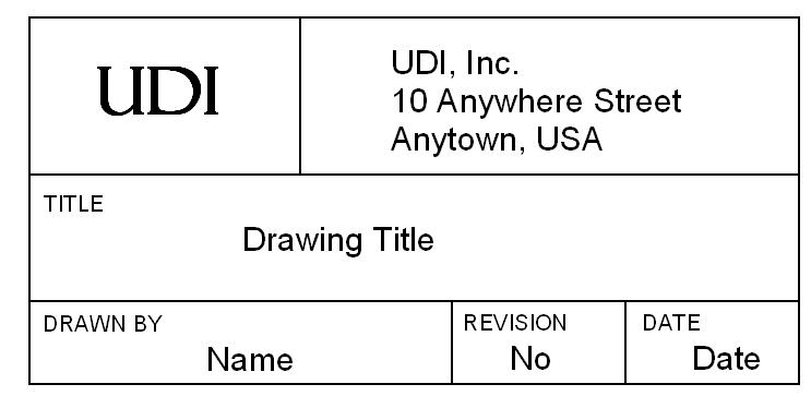
A title block containing drawing information can be added to the sheet border. Title blocks are saved as symbols with text linked to a record.
A title block can be the only part of the sheet border that displays, by selecting Use As Title Block Only in the sheet border preferences or the Object Info palette.
Additional title block capabilities are described in “Adding a Sheet Border” na página 74.
To add a title block to the sheet border:
1. Select the sheet border.
2. In the Object Info palette, click Title Block.
Alternatively, right-click (Windows) or Ctrl-click (Mac) on the sheet border and select Title Block from the context menu.
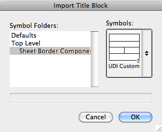
The Import Title Block dialog box opens.
Click to show/hide the parameters.
3. Select a title block symbol from the selected symbol folder. The Defaults folder contains the default title block resources; see “Resource Libraries” on page 215. The title blocks listed under Top Level are title block symbols that exist in the current file.
To remove an existing title block, select None.
4. Click OK to add the selected title block symbol to the sheet border. The title block is scaled to match the current layer scale if necessary.
When a sheet border with a title block is inserted into a drawing, the Sheet Border Components symbol folder is automatically created and displays in the Resource Browser. Title block symbols added to the sheet border are automatically placed in that folder.
~~~~~~~~~~~~~~~~~~~~~~~~~
 Editing
Revision Block Data
Editing
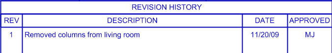
Revision Block DataTo add a revision block to the sheet border, select Use Revision Block from the Object Info palette of a selected sheet border. The revision block parameters (such as height and width) are specified from the Object Info palette, but the actual revisions are specified in a separate dialog box.
To add or edit revision block data:
1. From the Object Info palette of a selected sheet border with a revision block, click Edit Revision Data.
2. The Edit Revision Data dialog box opens.
Click to show/hide the parameters.
3. Click Add to create a revision entry.
The Add New Revision dialog box opens. Specify the revision data.
4. Click OK to return to the Edit Revision Data dialog box. Existing revisions can also be edited or deleted.
5. Click OK. The revision block is updated.
~~~~~~~~~~~~~~~~~~~~~~~~~
 Editing a
Tolerance Block
Editing a
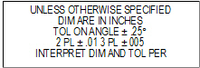
Tolerance BlockWhen an ASME title block is added to a sheet border, an area for tolerance specifications data is included. The tolerance data is specified in a separate dialog box.
To edit the tolerance block data:
1. Select the sheet border from the drawing area.
2. In the Object Info palette, click Edit Title Block.
The Edit Title Block dialog box opens. Click the Tolerance tab.
3. Enter the angular and dimensional tolerances to be displayed in the tolerance block.
Only the angular accuracy, two place, and three place parameters apply to the ASME tolerance block. The remaining tolerances might apply to a custom title block.
4. Click OK.
The tolerance block is updated with the new information.
~~~~~~~~~~~~~~~~~~~~~~~~~
 Editing
Issue Data
Editing
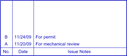
Issue DataWhen a US Arch title block is added to a sheet border, an area for issue data is included. The issue notes are specified in a separate dialog box.
To add or edit issue data:
1. From the Object Info palette of a selected sheet border with a revision block, click Edit Issue Data.
2. The Edit Issue Data dialog box opens.
Click to show/hide the parameters.
3. Click Add to create an issue entry.
The Add New Issue dialog box opens. Specify the issue note.
4. Click OK to return to the Edit Issue Data dialog box. Existing issue notes can also be edited or deleted.
5. Click OK. The issue data is updated.
~~~~~~~~~~~~~~~~~~~~~~~~~
A custom title block, containing company-specific graphics, information, and data fields, can be created and then inserted into a sheet border.
Three steps are required: create a title block symbol, create a custom record format, and link the record format fields to the title block symbol text fields.
Creating a custom title block in the Vectorworks Design Series products requires additional steps, if the custom title block is to be used with the Issue Manager.
To create a custom title block:
1. In a new file with a scale of 1:1, create the elements of the title block, including lines, rectangles, graphics, and text. Creating the title block at a scale of 1:1 ensures that it is inserted at the correct scale when it is placed on a sheet layer or a design layer of any scale. The title block should be a 2D screen object (See “Modos Planares de Objetos 2D: Plano de Tela e Plano de Camada” na página 147.)
• Do not use any 3D elements.
• Company logos can be imported as bitmaps.
• The title block geometry (pen color, pen style, and line thickness) and text (font, style, and color) can either inherit the sheet border attributes, or retain those attributes as created. The “By Class” setting in the Attributes palette indicates that the attributes should be inherited from the sheet border. If an attribute is not set to “By Class,” then its original setting is retained.
Description |
Method |
|---|---|
The attributes of the title block elements are inherited from the sheet border |
Specify “By Class” in the Attributes palette for these elements. For text font and style attributes, set the Pen Style by class to use the same font and style as the sheet border. For text color, set the Pen Color to “Color By Class.” |
The title block elements retain the attributes as created |
Set the attributes of the geometry and text from the Attributes palette when the title block is created. For text font and style attributes, set the Pen Style to Solid to use the text attributes set when the title block was created. For text color, select the desired Pen Color. |
Different settings can be combined so that some attributes are inherited from the sheet border, while others remain as created. For example, if a line should use the same color as the sheet border, but have a dashed line type with a thickness of 1 mm, when creating the line, set the line’s Pen Color to “Color By Class,” its Line Thickness to 1 mm, and its Pen Style to the desired dashed line type.
2. Select all the title block elements, and then select Modify > Create Symbol.
The insertion point of the symbol should be at lower right corner of the title block. See “Criando Novos Símbolo” na página 235.
3. Create a new record format as described in “Criando Formatos de Registro” na página 257.
The field names of the record format are used as the titles for the associated editable fields in the Edit Title Block dialog box.
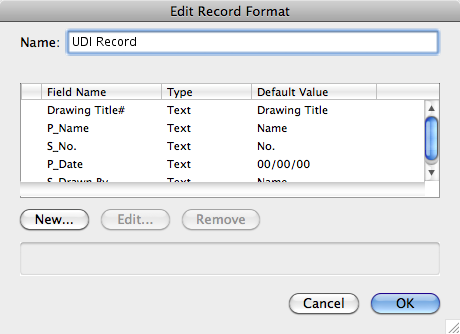
To create a multi-line field, append a pound sign (#) to the field name, as in Drawing Title#.
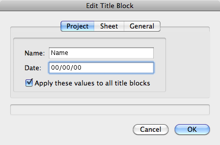
Use a P_ prefix to indicate project fields (these are fields with the same value on all title blocks in the file). An S_ prefix indicates sheet fields (these are fields with a different value on any title blocks). The prefixes cause the Edit Title Block dialog box, accessed from the Object Info palette, to be separated into project and sheet tabs. Fields without a prefix are placed on the General tab.
Use an _SN suffix to indicate that a field should gets its value from the Sheet Number of its sheet layer. If Use Automatic Drawing Coordination is enabled in document preferences (Vectorworks Design Series required), the _SN suffix also means that when this title block field is updated, the Sheet Number of the sheet layer and of annotation objects on the layer are updated.
Use an _SD suffix to indicate that the field should get its value from the Sheet Title of its sheet layer. If Use Automatic Drawing Coordination is enabled in document preferences (Vectorworks Design Series required), the _SD suffix also means that when this title block field is updated, the Sheet Title of the sheet layer is updated. If the field should also be multi-line, use an _SD# suffix.
4. Creating a custom title block in the Vectorworks Design Series products requires additional steps, if the custom title block is to be used with the Issue Manager (see “The Issue Manager” na página 86), or contain issue fields or revision fields. When creating the record format to attach to the custom title block, fields linked to the Issue Manager require special prefixes or suffixes. If creating issue or revision fields, special text strings are added to the title block design. These record fields do not require linking, as they are automatically recognized by the Vectorworks program.
Title Block Area |
Prefix Required |
|---|---|
Issue Manager |
If you are creating a US Arch-style title block with issue data linked to the Issue Manager: • Project fields (which contain the same value in all drawing set title blocks) must be prefaced with P_ (example: P_Project Title) • Sheet fields (which contain different values in different drawing set title blocks) must be prefaced with S_ (example: S_Sheet Scale) • Multi-line text fields (which contain multiple lines of text) must be appended with a # (pound sign) (example: P_Drawing Title#) |
Issue Data |
To add issue fields, such as issue number, date, note, and/or approvals to a sheet border which can be populated by the Issue Manager and edited manually, create text fields with special text strings to represent the issue fields and place these fields in the title block. The special text strings are (including colon): • Issue note :iNote • Issue number :iNo • Issue date :iDate • Issue approval :iAppr The text fields can have any justification, and should have word wrap on. The vertical alignment must be set to Top for the issue text to flow down, and to Bottom for the issue text to flow up. To enter or edit issue text, click Edit Issue Data from the Object Info palette of a selected sheet border (see “Editing Issue Data” na página 81), or use the Issue Manager. The issue history is a property of the sheet border, not the title block, so a title block is not required to enter issue data. |
Revision Data |
To add revision fields, such as revision number, date, zone, and/or approvals to a sheet border, create text fields with special text strings to represent the revisions and place these fields in the title block. The special text strings are (including colon): • Revision note :rNote • Revision number :rNo • Revision date :rDate • Revision zone :rZone • Revision approval :rAppr The text fields can have any justification, and should have word wrap on. The vertical alignment must be set to Top for the revision text to flow down, and to Bottom for the revision text to flow up. To add revision text to a sheet border, select Use Revision Block from the Object Info palette of a selected sheet border. To enter or edit the revision text, click Edit Revision Data (see “Editing Revision Block Data” na página 80). The revision history is a property of the sheet border, not the title block, so a title block is not required to enter revision data. |
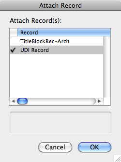
5. Attach the custom record format to the title block symbol through the Resource Browser as described in “Associando Formatos de Registro a uma Instância de Símbolo ou Objeto” na página 258.
6. Edit the title block symbol and attach the record fields to the associated symbol text; see “Ligando Textos à Formatos de Registros” na página 263 for more information.
7. To be available to the Sheet Border tool, either the file must be saved in the sheet border- title block folder in the [Vectorworks]\Libraries\Defaults folder, or the custom symbol and its associated record format must be imported into the Custom Title Blocks.vwx file, located in the same default content folder.
Alternatively, import the title block symbol from another file.
8. To place the custom title block, click Title Block from the Object Info palette of a selected sheet border, and select the custom title block symbol.
~~~~~~~~~~~~~~~~~~~~~~~~~
 The Issue
Manager
The Issue
ManagerThe Issue Manager accesses and displays information about drawing issue, dates, and history on a sheet-by-sheet basis. It interacts with the sheet border object by allowing the user to control the sheet border title block data and issue information. (Sheet borders can either be placed with the Sheet Border tool in the Dims/Notes tool set—see “Adding a Sheet Border” na página 74—or created and placed by the Document Setup or Create Standard Viewports commands—see “Document Setup” na página 73 and “Standard Viewports” na página 181.)
To use the Issue Manager:
1. Ensure that at least one sheet border with a title block is present in the drawing.
2. Select File > Issue Manager.
The Issue Manager dialog box opens.
The tabs and fields displayed depend on the title block inserted in the sheet border. Custom title blocks may not match the parameters or tabs shown here. The fields and tabs shown assume that an Arch-style title block is inserted.
3. Click the Project Data tab to configure the project information.
Leave a blank field to create an empty line in the title block.
Click to show/hide the parameters.
The information on the Project tab applies to all sheet borders or title blocks in the set.
4. Enter the project information. If the project was created with the Create Standard Viewports command, some of the information has been automatically entered.
5. Click the Sheet Data tab to configure information about individual sheet layers in the set.
Click to show/hide the parameters.
6. Complete the information for each sheet in the drawing set to be issued. Toggle among other sheets in the drawing with the Next and Prev buttons.
If the project was set up with the Create Standard Viewports command, some of the information has been automatically entered. For each sheet, specify sheet-specific information and indicate whether to include the sheet in the issue.
7. Click the Issue Data tab to specify information about the current issue.
Click to show/hide the parameters.
8. Click OK.
The sheet border title blocks are updated for the selected sheets. If specified, the issue information is included in the title block.
Regardless of whether the title block contains fields for the issue data, the data is still written to a record attached to the sheet border, becoming a permanent part of the sheet border. If the title block changes later, the data can be displayed.
 Standard Naming
The Standard Naming command controls the layer, class, and viewport names used in a project. These names can be changed to a user-defined system other than the default VWArch naming system. Standards can be mapped for office-wide use or to convert an existing file to the office standard. This command can also be used to assign specific attributes to classes in standards, and to change the names of layers, viewports/views and classes in the current standard. The command does not create new layers, classes, or viewports/views.
If classes, layers, and viewports/views have not been set up according to VWArch standards, their names may not match the example layer and class names presented here.
To set the standard naming of layers, classes, and views:
1. Select File > Document Settings > Standard Naming.
The Standard Naming dialog box opens. Select a naming standard for the file, and choose whether auto-classing should be enabled for objects.
Click to show/hide the parameters.
2. Click Details to edit custom class, layer, and viewport/view names.
The Standard Naming Details dialog box opens, displaying class names on the Classes tab. Select the Design Layers tab to display design layer names, and the Sheet Layers, VP, Saved Views tab to display the names for viewports and their associated sheet layers, or for saved views.
Using the reference list, verify the mapping of standard names. Custom naming can be specified for custom active standards by entering a new name for each layer, class, or viewport/view. If desired, class attributes can also be specified for each standard or custom class name. See “A Paleta de Atributos” na página 1091.
Click to show/hide the parameters.
3. When the desired class attributes have been specified, and, for custom standards, the standard names have been established, click OK.
4. In the Standard Naming dialog box, click OK. If custom viewports exist in the drawing, you are prompted to run the Create Standard Viewports command again (see “Creating Standard Viewports” na página 182) to update the viewports/views with the new naming standard, and update any new class attributes. If auto-classing was selected and objects had already been placed in the drawing, select whether to auto-class those existing objects.
Click here for a video tip about this topic (Internet access required).
~~~~~~~~~~~~~~~~~~~~~~~~~
 Creating
Additional Custom Standards
Creating
Additional Custom StandardsA custom naming standard can be created rather than using the VWArch or AIA/NCS standard. Although three layer, class, and viewport/view standards are available from within the Standard Naming dialog box (User 1, User 2 and User 3), up to ninety-nine can be created for layers, classes, and viewport/views by editing the ClassNameStds, LayerNameStds, and ViewNameStds worksheets. See “Using Worksheets” on page 1315.
To create a custom naming standard by worksheet:
1. In a new file, select File > Document Settings > Standard Naming.
The Standard Naming dialog box opens.
2. Without making any changes, click OK.
Three worksheets are created in the file, and are visible in the Resource Browser: ClassNameStds, LayerNameStds, and ViewNameStds.
3. Select one of the worksheets from the Resource Browser, and select Resources > Open.
The worksheet opens for editing.
4. Highlight column D (User 1) and from the Worksheet menu select Insert > Columns. A new column is added in front of the selected one.
New columns must be inserted after the AIA/NCS column and before the Description or Pen Color column.
5. Enter a name in cell D1 for the new standard.
6. Enter a new standard name for each cell below D1.
Cells left blank in the ClassNameStds worksheet will be assigned to the “None” class. Cells left blank in the LayerNameStds worksheet will be assigned to the “Layer-None” layer. Blank cells are not permitted in the ViewNameStds worksheet; if a worksheet with blank viewport/view names is attempted for use in Standard Naming, an error message is displayed.
7. The new standard is displayed in the Standard Naming dialog box.
To use these changes in other files, either save the file as a template to be used as the basis for new drawings, or import each worksheet into the other file before running the Standard Naming command.
When creating custom standard naming, naming standards may contain fewer standard names (coarser) or additional standard names (finer).
A “coarser” custom standard names two or more of the standard class, layer, or view names with the same user-defined name. Except for auto-classing, this is an irreversible process.
For example, the classes Area-Main, Area-Patterns, and Area-Spec can be combined into a single class called Areas. All objects assigned to the original three classes are reassigned to Areas.
When custom standard naming changes are complete, additional information displays to confirm any actions to be taken, such as merging changed class names to eliminate duplicates.
A “finer” standard maps a single class, layer, or view name to multiple names. Mapping is required to define the standard naming change, and the Standard Naming - Mapping dialog box opens automatically.
For example, an A-FP# layer AIA standard corresponds to two layer standards in the Vectorworks Architect product: Mod-Floor-# and Mod-Slab-#. If switching from the AIA standard to the VWArch standard, select the A-FP# layer from the list on the left and indicate the mapping for objects currently on the A-FP# layer by selecting the mapping layer on the right.
All objects assigned to the A-FP# layer are assigned to the Mod-Floor-# layer. Unmapped layers are not created.
 Mapping Classes and Layers
The Class and Layer Mapping command “maps” any set of layers and/or classes in a drawing into a new layer and/or class. The file structure can be simplified, condensed, and/or renamed. Use this feature, for example, when a consultant is using DWG or DXF files. Complex, multi-classed files imported from DWG can be condensed or renamed, and empty classes deleted in a single operation. Mapping can be saved so the next time a file is received from that consultant, the file can be re-mapped in a single step. This same procedure can be revised for the process of providing files to consultants using a different file structure or drawing standard. See “Administrando Camadas” na página 156 and “Classes” na página 171.
To modify layers and classes:
1. Select Tools > Class and Layer Mapping.
The Class Mapping dialog box opens. Modify the existing classes, and then click Go To Layers to open the Layer Mapping dialog box. The Layer Mapping dialog box is identical in layout to the Class Mapping dialog box.
Parameter |
Description |
|---|---|
Existing Classes/Layers |
Lists the existing classes or layers in the file; layers or classes that are not moved to the Proposed or Merged list are deleted |
Add > |
Adds a layer or class from the list of existing layers or classes to the Proposed list |
Merge > |
Adds a layer or class to the Merged list; layers or classes in this list will be merged with the layer or class that is selected in the Proposed list |
< Remove |
Removes the selected item from the Proposed list |
New |
Creates a new class or layer in the Proposed list |
Rename |
Renames the selected proposed layer or class |
Merged Items |
Lists layers or classes to merge with the selected layer or class in the Proposed list. The merge occurs when the next action is performed in the dialog box, so that layers and classes are merged on an ongoing basis. Selecting a proposed layer or class lists its merged items again so that changes can be made, if desired. |
Remove |
Removes the selected item from the Merged list |
Load |
Opens a previously saved mapping file |
Save |
Saves the layer or class mapping as a file; layer and class mapping settings are saved separately. This saves time when making the same modifications to several drawings that are set up similarly. |
Reset All |
Moves all proposed and merged items back to the Existing list |
Delete empty class/layer in proposed drawing |
Deletes all layers and classes that have no items associated with them |
Go To Layers > /Go To Classes > |
Toggles between the Class Mapping and Layer Mapping dialog boxes |
When selecting existing and proposed classes and layers, press and hold the Shift key to select multiple, contiguous items or press and hold the Ctrl key (Windows) or Command key (Mac) to select non-contiguous items.
2. Click OK.
The drawing is updated, using the new layer and class mapping. Layers and classes not moved to the Proposed or Merged list are deleted from the file, along with any objects in those layers or classes.
 Spotlight Setup
The options on the Lighting Device tab enable automatic positioning behavior, assign classes, and specify attributes of the lighting devices in the file. The parameters selected can have a powerful global effect on all the devices, both existing and new.
Lighting instruments can be automatically associated with a lighting position, both at insertion and when an existing instrument is moved on the light plot. At various times during the design work, particularly in the later stages, instruments may need to be moved slightly, but they should not be accidentally associated with a different nearby lighting position. The auto-positioning option provides the necessary control over the automatic association of instruments to lighting positions.
Class and color assignments for lighting instruments allow the designer to:
• Assign the lighting instruments to a specific class, or to one or more classes determined by an instrument parameter
• Control the color of lighting instruments, or parts of instruments, by gel color or from the Attributes palette
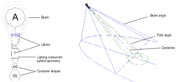
• Control the wireframe light beams, angles, and centerline of lighting instruments by class
• Control the label legend container appearance by class
• Control the appearance and visibility of lighting instruments in viewports, when using viewport overrides
The Object Info palette display of lighting device parameters can also be set from this tab.
To specify lighting device preferences:
1. Select File > Document Settings > Spotlight Preferences.
The Spotlight Preferences dialog box opens. Click the Lighting Device tab.
Click to show/hide the parameters.
2. Specify the auto-positioning and appearance settings for the file’s lighting devices.
Click Save as default to use the lighting device and other Spotlight settings for other files created with the Vectorworks Spotlight product.
3. Click OK.
Class setting changes require confirmation before regenerating the lighting devices.
The lighting device parameters that display on the Shape tab of the Object Info palette can be customized. The customized parameters apply to all lighting devices in the file, and parameter sets can be saved.
To specify lighting device parameters:
1. Select File > Document Settings > Spotlight Preferences.
2. The Spotlight Preferences dialog box opens. Click the Lighting Device tab.
3. Click Lighting Device Parameters.
The Lighting Device Parameters dialog box opens. From this dialog box, Object Info palette parameters for lighting devices can be added, renamed, deleted, removed from display, and ordered. Parameter sets can be saved and managed.
Default lighting device parameters cannot be deleted.
Click to show/hide the parameters.
4. If settings have been changed, save the current settings as a set by clicking Save; <customized> is not considered as a saved set, though it applies to the current file.
5. Click OK to return to the Spotlight Preferences dialog box. The parameter display set that was selected applies to the current file.
Regardless of whether Save as default is clicked in the Spotlight Preferences dialog box, the last selected saved set of parameters is in effect, even when creating a new file. New files created in Vectorworks Spotlight always default to the last saved parameter set.
~~~~~~~~~~~~~~~~~~~~~~~~~
 Universe
Assignment in Vectorworks Spotlight
Universe
Assignment in Vectorworks SpotlightAt the beginning of a project (and at any other time), the Vectorworks Spotlight product can be set to automatically handle the assignment of DMX universe and dimmer combinations. As instruments are added to the light plot, the U Dimmer and Universe instrument parameters are determined based on the dimmer numbers specified in the Spotlight Preferences dialog box.
To specify the dimmer and universe assignment:
1. Select File > Document Settings > Spotlight Preferences.
The Spotlight Preferences dialog box opens. Click the Universe tab.
Click to show/hide the parameters.
2. To enable automatic universe assignment, click Automatically assign Universe.
3. Select a universe system and then for each universe in the system, provide a name (optional) and a starting and ending value. Click Next Page to continue entering universe break values.
Click Save as default to use this universe assignment and other Spotlight preferences for other files created with the Vectorworks Spotlight product.
4. Click OK.
The dimmer numbers of inserted instruments are automatically assigned to a universe. The U Dimmer parameter in the Object Info palette displays the automatically assigned dimmer number when automatic assignment is on.
~~~~~~~~~~~~~~~~~~~~~~~~~
 Project Setup for Mechanical
Design
Project Setup for Mechanical
DesignAt the beginning of a mechanical design project, use the Drawing Setup command to quickly set relevant drawing units, layer scale and print area from a single dialog box. A sheet border and title block can also be inserted automatically. An alternate method of setting up a document is to open one of the pre-configured machine design template files and use it as a starting point.
The Machine Design (Imperial) template opens with File > Document Settings > Units set to inches on the General Display tab, decimal rounding set to three decimal places, and the design layer scale set at 1:1.
To set up a project with the Drawing Setup command:
1. Select File > New.
The Create Document dialog box opens.
2. Select Create blank document, and then click OK.
3. Select the Drawing Setup command from the appropriate menu:
• Architect: AEC > Machine Design > Drawing Setup
• Landmark: Landmark > Machine Design > Drawing Setup
• Spotlight: Spotlight > Machine Design > Drawing Setup
The Drawing Setup dialog box opens.
4. Specify the drawing units, layer scale, print area, and sheet border, and then click OK. For more information on Drawing Units, Layer Scale, and the Print Area, see “Definição do Desenho” na página 65.
Click to show/hide the parameters.
The drawing setup parameters are saved with the file. Use the Object Info palette to make any changes to the sheet border once it has been placed in the drawing.