Lighting
Design WorkflowLighting
Design Workflow
Lighting
Design WorkflowLighting
Design WorkflowThe Vectorworks Spotlight product provides the lighting designer with all the tools necessary to plan and create a light plot and its associated paperwork. We recommend the following general workflow.
A note about terminology as used to discuss lighting design in Vectorworks Spotlight: a lighting device consists of a lighting instrument, and optionally, an accessory; these are placed on a lighting position. In the Vectorworks Spotlight program, a lighting instrument is a lighting device with a Device Type of Light, Moving Light, Device, Practical, SFX, Power, or Other. An accessory is a lighting device with a Device Type of Accessory or Static accessory.
1. Create a template file that you can use to start new design files, or from which you can import standard elements into other files. The template can contain all of the resources, classes, and design layers you use on a regular basis. You might also set options you commonly use, such as the default object attributes and page size. It is recommended that you plan to place the stage, focus points, and scenic elements on separate design layers; plan to place the lighting positions, lighting instruments, and accessories together on one layer. All design layers should use the same scale. Select the File > Save As Template command to save the file.
2. Create a new project file from your template file.
3. Select the File > Document Settings > Spotlight Preferences command to set default lighting device parameters, and to specify whether universe assignment should be handled automatically. If you use Lightwright, set up automatic data exchange; this creates a file with the same name as the Vectorworks file with an .xml file extension, which you can then open in Lightwright. Changes that you make in both the Lightwright and Vectorworks programs are shared seamlessly.
4. Copy or import design elements (such as theater architecture or scenic designs) from other files, as needed. From a Vectorworks file, you can paste or import items directly into your file (you might want to apply your own classes to them first). Alternatively, create a design layer viewport to reference an external Vectorworks file; your file will be updated automatically if the external file changes, and the external classes will not be imported into your file. The Vectorworks program can also import drawing elements from several file types, such as DXF/DWG, PDF, and SketchUp.
5. Use the Lighting Pipe, Lighting Pipe Ladder, Straight Truss, and Curved Truss tools to create lighting position geometry. You can also draw your own 2D or 2D/3D geometry. Select the Spotlight > Object Conversion > Convert to Light Position command to convert each object into a light position. From the Object Info palette, enter a Z value to indicate the height of each position.
6. To use the same geometry for multiple lighting positions, select the option to create a symbol when you convert the geometry. Make the symbol active in the Resource Browser, and then use the Lighting Position tool to insert additional lighting positions.
7. Use the Focus Point tool to create focus areas. In step 10, you will assign these focus points to specific lighting instruments.
8. Select the Label Legend Manager command to create label legends for your lighting instruments. The label legend specifies which data fields to display for the instruments, as well as how the fields are laid out.
9. Select the Lighting Instrument tool to place lighting instruments on the lighting positions. Thousands of instrument symbols are available for import, from resource libraries provided with the Vectorworks application, from subscription libraries available through Vectorworks Service Select, and from third-party providers.
The lighting instruments in the Vectorworks Spotlight product represent more than simply a graphical symbol. An instrument contains design information, such as labels, focus, position, channel, and color. Instruments are labeled with lighting information according to the label legend format. Use the standard instrument symbols, or convert your own custom symbols to instruments.
You can also draw your own instrument symbols as needed. The position and instrument height are filled in automatically according to the lighting position.
From the Object Info palette, specify the instrument purpose, color, and dimmer.
10. Select the Spotlight > Focus Instruments command to specify a focus point for each instrument.
11. Use the Accessory Insertion tool to add accessories to lighting instruments. As with lighting instruments, a wide variety of accessory symbols are available for import, or you can draw your own.
12. Fine-tune the lighting design using the following tools and commands:
• Select the Draw Beam option in the Object Info palette and check the light beam and field for each lighting instrument.
• Use the Photometer and PhotoGrid tools to check the footcandles present at specific spots on the stage.
• Use the Align and Distribute Items tool to more precisely align instruments to their positions.
• Select the Spotlight > Visualization > Create Plot and Model View command to automatically create a 3D model for a selected vertical or angled lighting position. This creates a design layer viewport on a model layer, which can be rotated to show the lighting position accurately in sections and elevations.
13. Use the Soft Goods tool to insert curtains, borders, scrims, and pipe-and-drape assemblies where needed.
14. Generate paperwork for yourself and others using one or more of the following commands:
• Select the Spotlight > Reports > Generate Paperwork command to create an instrument schedule and other typical electrician paperwork from within the Vectorworks program.
• Select the Spotlight > Reports > Create Report command to create a database worksheet, which allows you to edit lighting instrument data in a spreadsheet format from within the Vectorworks program.
• If you use the Lightwright automatic data exchange feature, your exchange file is ready to share when needed.
15. Use the Instrument Summary tool to create a summary graphic of the instruments and accessories that are used in the light plot. To create a summary graphic for a selected lighting position, click Insert Position Summary in the Object Info palette. To compare the required totals to current inventory, select the Spotlight > Reports > Lighting Inventory Setup command to enter inventory information.
16. Use commands on the View menu (Create Viewport, Create Detail Viewport, Create Section Viewport) to create the viewports you want to print or export, such as the main light plot, detail views, section views, and hanging cards. Show or hide classes and layers, and add title blocks, borders, dimensions, and notes as needed.
17. Print or export the sheet layers, as needed. The File > Publish command allows you to easily publish selected sheet layers to a printer, or to PDF, DXF/DWG, DWF, and image files. You can also save the publish settings and use them again later. The File > Export menu has options for exporting to several additional file types.
~~~~~~~~~~~~~~~~~~~~~~~~~
 Light
Plot Structure
Light
Plot StructureA structured system of layers and classes makes selecting, viewing, and printing items considerably easier. When creating a light plot, develop a standard layer and class structure, along with a system for assigning items to the appropriate layers and classes. Some objects include the ability to be automatically assigned to classes.
For more information on layers and classes, see “Layers” on page 157 and “Classes” on page 172.
We recommend that you place the stage, focus points, and scenic elements in separate design layers; place the lighting positions, lighting instruments, and accessories together on one layer. Select Tools > Organization and click the Design Layers tab to create and manage layers.
Use the same scale for all the design layers.
Place light plot items in their own classes. This allows you to globally turn off the display of certain classes for viewing and printing. Select Tools > Organization and click the Classes tab to create and manage classes. Lighting devices can be automatically assigned to classes determined at setup; see “Lighting Device Setup” on page 92.
The Vectorworks Spotlight product automatically creates certain classes to control instrument label visibility. These include the Label class and its subclasses, and the Setup Notes class.
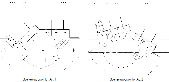
An example of the use of layers and classes would be a show file with all of the scenery on a single design layer, and classes created to represent Act 1 and Act 2. When adding scenic elements, place them on the scenery design layer, and assign them to either the Act 1 or Act 2 class. With this structure, use layer visibility to view only the scenery design layer, and class visibility to turn the Act 1 or Act 2 classes on and off. This method allows you to view the position of the set pieces in each act independently.
Another way to take advantage of structuring is to also use classes for the lighting devices. In a situation with multiple shows in repertory, assign each device to the class of the show where it is used. This allows you to display each show’s devices independently of the other shows.
 Creating Lighting Positions
Lighting positions represent the hanging points for instruments; they should be placed on the light plot before the instruments are added. Lighting positions manage the numbering of instruments according to the instruments’ location on the lighting position.
Defining the lighting positions first is useful because once the space has been created, with the stage and lighting positions defined, the file can be used as a template for future light plots in that space. For more information on creating templates, see “Criando Gabaritos” on page 73.
Place the lighting positions in their own design layer and in their own classes. A drawing structure based on layers and classes facilitates selecting, viewing, and printing the light plot.
Creating lighting positions is generally a two-step process. First, insert or draw the geometry of the lighting position. Then, convert the object or geometry into an intelligent lighting position symbol, ready for instrument placement.
Several different types of objects can be used as the basis for a lighting position symbol:
• Lighting pipes
• Lighting pipe ladders
• Straight trusses
• Curved trusses
• Custom 2D or 2D/3D geometry that you draw
Once one of these objects has been configured, convert it into an intelligent lighting position symbol with the Convert to Light Position command. The symbol displays in the Resource Browser. For more information about symbols, see “Symbols” on page 233.
Use the Lighting Position tool to insert symbols from the current file, the symbol libraries, or a Favorites file.
~~~~~~~~~~~~~~~~~~~~~~~~~
 Placing
Lighting Pipe Objects
Placing
Lighting Pipe ObjectsInsert and configure a lighting pipe object with the Lighting Pipe tool.

To insert a lighting pipe object:
1. Click the Lighting Pipe tool from the Spotlight tool set.
Alternatively, create a polyline and then select the Create Objects from Shapes command (see “Creating Objects from Shapes” on page 273).
2. Click in the drawing area to begin drawing the lighting pipe.
If this is the first time a lighting pipe has been placed on the drawing, the Properties dialog box opens. Specify the preferences to use for this tool during this session, and then click OK.
3. To draw a multi-segment pipe, click to set the end of one segment and start the next.
Create a curved pipe by changing the vertex type (see “Creating Polylines” on page 294).
4. Double-click to complete the lighting pipe polyline.
The lighting pipe parameters can be edited in the Object Info palette.
Click to show/hide the parameters.
To use the lighting pipe as a lighting position, convert it to a lighting position symbol; see “Creating a Lighting Position Symbol” on page 865.
~~~~~~~~~~~~~~~~~~~~~~~~~
 Placing Lighting Pipe Ladders
Insert and configure a lighting pipe ladder with the Lighting Pipe Ladder tool.

To insert a lighting pipe ladder:
1. Click the Lighting Pipe Ladder tool from the Spotlight tool set.
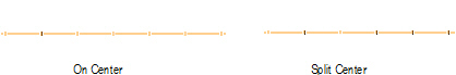
2. Click in the drawing area to insert the ladder. The ladder is a rectangular object, and can be inserted in Center-line Placement mode or Edge Placement mode.
Placement Mode |
Description |
|---|---|
Center-line |
Click once, and then again, to define the width through the center of the ladder. Click again to specify the width of half the ladder. |
Edge |
Click once, and then again, to define the length along the edge of the ladder. Click again to specify the grid ladder width. |
If this is the first time a lighting pipe ladder has been placed on the drawing, the Properties dialog box opens. Specify the preferences to use for this tool during this session, and then click OK.
The lighting pipe ladder parameters can be edited in the Object Info palette.
Click to show/hide the parameters.
To use the lighting pipe ladder as a lighting position, convert it to a lighting position symbol; see “Creating a Lighting Position Symbol” on page 865.
~~~~~~~~~~~~~~~~~~~~~~~~~
 Inserting
a Straight Truss
Inserting
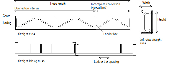
a Straight TrussStraight truss parameters are illustrated by the following diagram.

To add a straight truss to the light plot:
1. Click the Straight Truss tool from the appropriate tool set.
• Spotlight: Spotlight tool set
• Designer: Detailing tool set
2. Click in the drawing area where the truss will be located and draw a line to indicate the length of the truss. If this is the first time a straight truss has been placed on the drawing, the Properties dialog box opens. Specify the preferences to use for this tool during this session, and then click OK.
The straight truss properties can be edited later in the Object Info palette.
Trusses are 2D/3D hybrid objects. Complex trusses can increase the time required to render the model in 3D.
Click to show/hide the parameters.
A connection interval shorter than the defined interval length is displayed in red when Highlight is selected.
To use the truss as a lighting position, convert it to a lighting position symbol; see “Creating a Lighting Position Symbol” on page 865.
~~~~~~~~~~~~~~~~~~~~~~~~~
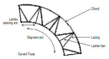
 Inserting
a Curved Truss
Inserting
a Curved TrussCurved truss parameters are illustrated by the following diagram.

To add a curved truss to the light plot:
1. Click the Curved Truss tool from the appropriate tool set:
• Spotlight: Spotlight tool set.
• Designer: Detailing tool set
2. Click to define the truss insertion point. Click again to set the rotation of the curved truss. If this is the first time a curved truss has been placed on the drawing, the Properties dialog box opens. Specify the preferences to use for this tool during this session, and then click OK.
The curved truss properties can be edited later in the Object Info palette.
Trusses are 2D/3D hybrid objects. Complex trusses can increase the time required to render the model in 3D.
Click to show/hide the parameters.
If the final segment of a truss is shorter than the defined interval length, it is displayed in red when Highlight is selected.
To use the truss as a lighting position, convert it to a lighting position symbol; see “Creating a Lighting Position Symbol” on page 865.
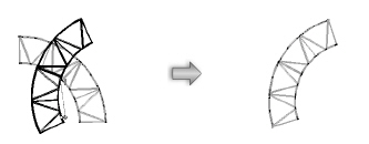
A curved truss can be rotated with the Rotate tool.
To rotate a curved truss:
1. Select the truss. In the Object Info palette, select Draw 3D Only.
2. Click the Rotate tool from the Basic palette.
3. Click to set a fulcrum line; click to end. Move the cursor to rotate the truss, and then click to set the rotation.
Click here for a video tip about this topic (Internet access required).
~~~~~~~~~~~~~~~~~~~~~~~~~
 Truss
Configuration Requirements
Truss
Configuration RequirementsA great deal of flexibility is incorporated in the Spotlight truss object. However, in order to create a valid truss, the wide variety of configurations leads to certain restrictions in the application of truss properties.
If a truss is drawn that does not meet these requirements, an alert message is generated.
• The width and height of the truss must be greater than three times the chord width
• The truss hanging angle must be between -90° and +90°
• A triangular truss must form a valid triangle
• The chord diameter must be greater than zero
• A pre-rigged truss cannot have lacing
• A pre-rigged truss cannot be folding
• Only box trusses can be pre-rigged
• A folding truss cannot have top lacing
• Folding is not allowed on a stacking truss
• Top lacing is not allowed on a stacking truss
• The top brace diameter must be less than or equal to the chord width
• The side brace diameter must be less than or equal to the chord width
• The connection interval must be greater than the ladder bar spacing
• Ladder bar spacing must be greater than three times the top brace size
• If the section is too small, lacing may not be drawn
~~~~~~~~~~~~~~~~~~~~~~~~~
 Creating a Lighting Position Symbol
As described in “Creating Lighting Positions” on page 856, you can create lighting position geometry by placing a Spotlight lighting pipe, ladder, or truss object. You can also create your own geometry for conversion. At a minimum, a lighting position symbol requires at least a 2D component; it also requires a 3D component to display correctly in 3D views. For more information on symbols, see “Symbols” on page 233.
When you have placed the lighting position geometry in the drawing, convert it to a lighting position symbol. As a symbol, it is available in the Resource Browser, where you can easily insert it into the drawing again, or reference or export it to other files.
To convert lighting position geometry to a lighting position symbol:
1. To convert multiple objects to a single lighting position, select Modify > Group and group the objects first.
2. Select the geometry.
3. Select Spotlight > Object Conversion > Convert to Light Position.
4. The Enter String dialog box opens; specify the name of the lighting position, and then click OK.
The selected object is converted to a lighting position symbol that remains inserted in the drawing. (If multiple items were selected for conversion, each object is converted one at a time.) Instruments can then be placed on the lighting position.
Select the lighting position from the Resource Browser as an active symbol definition and use the Lighting Position tool to insert it again if required.

~~~~~~~~~~~~~~~~~~~~~~~~~
 Inserting
Lighting Positions
Inserting
Lighting Positions Insert a lighting position symbol from the Resource Browser with the Lighting Position tool. This can be a symbol that you have created, or it can be one of the symbols imported from the libraries included with the Vectorworks Spotlight software ([Vectorworks]\Libraries); see “Resource Libraries” on page 215.

To insert a lighting position symbol:
1. Click the Lighting Position tool from the Spotlight tool set.
2. Select the desired lighting position symbol from the Resource Browser and choose Resources > Make Active to make it the active symbol definition. Alternatively, double-click on the symbol to activate it.
3. Click in the drawing to insert the active lighting position symbol definition, and then click again to set the lighting position rotation.
If the lighting position symbol is inserted without first clicking on the Lighting Position tool, the symbol is inserted by the Symbol Insertion tool. However, the lighting position functionality will not be present. When correctly inserted, the Object Info palette displays “Lighting Position” for the selected lighting position.
Once the Lighting Position tool has been selected, it remains selected by default so that lighting positions can be repeatedly inserted. To place non-lighting position symbols after placing lighting positions, switch to the Symbol Insertion tool.
4. A different type of lighting position can be placed by changing the active symbol definition and continuing to use the Lighting Position tool.
The lighting position object parameters can be edited in the Object Info palette.
Click to show/hide the parameters.
The Z value of a lighting position can only be specified for lighting positions with 3D geometry. However, the Z value can be specified for the lighting instruments placed on any type of lighting position (2D, 3D, or hybrid). A lighting position created from a symbol or plug-in object automatically assumes the Z value of the original object.
If a lighting position is copied, it is automatically renamed; any associated duplicated lighting instruments are associated with the new lighting position. Deleting a lighting position does not delete the associated lighting instruments.
If instruments are moved to a different lighting position, the lighting position name is automatically updated for the instruments and the Z-height of the instruments is calculated automatically based on the lighting position Z-height.
~~~~~~~~~~~~~~~~~~~~~~~~~
 Setting
Up Instrument Label Legends
Setting
Up Instrument Label LegendsLabel legends specify the labels and label formatting for lighting instruments on the light plot. Multiple label legends can be defined and then selectively applied to different instruments. The active label legend is applied to instruments as they are placed, or a label legend can be selected for existing instruments from the Object Info palette. Label legends are 2D screen plane objects. (See “Planar Modes of 2D Objects: Screen Plane and Layer Plane” on page 148).
Click here for a video tip about this topic (Internet access required).
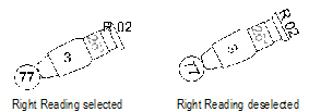
Each label is automatically placed in its own Label class. This allows the labels to be globally turned on and off. For example, if the designer is printing the light plot for an electrician, the “Label-Purpose” class of labels can be hidden so that only electrical information labels are shown.
The labels display the lighting instrument object information. The instrument Object Info palette also shows this information (see “Lighting Instrument Properties” on page 876).
The Label Legend Manager controls the setup and modification of the instrument label styles. Select Spotlight > Label Legend > Label Legend Manager to set up the legends for the light plot. The Label Legend Manager dialog box opens.
Click to show/hide the parameters.
~~~~~~~~~~~~~~~~~~~~~~~~~
 Creating
Label Legends
Creating
Label LegendsTo create a new legend:
1. In the Label Legend Manager dialog box, click Add.
The Add New Legend dialog box opens. Select the labels for placement and specify their attributes. Indicate the instrument symbol to use when formatting the label legend, and select whether the legend rotates with the instrument.
Click to show/hide the parameters.
Custom container symbols can be added to the list of available containers. Draw a container object, and then click Modify > Create Symbol. Enter a name for the container; click OK. In the Move Symbol dialog box, specify the location of the Containers folder and click OK. The symbol is added to the list of available containers. Any symbol can be placed in the containers folder and used as a label container. The pre-defined container symbols can also be edited and customized.
Container attributes can be determined by the label text or lighting device; see “Lighting Device Setup” on page 92
2. When all the label items and attributes have been specified for the legend, click OK. The new legend name displays in the Legend Name list in the Label Legend Manager dialog box.
3. Once the legend has been created, it needs to be formatted. See “Formatting the Label Legend” on page 870.
~~~~~~~~~~~~~~~~~~~~~~~~~
 Editing
Label Legends
Editing
Label Legends1. In the Label Legend Manager dialog box, select the legend, and then click Edit Fields. The Edit Label Legend dialog box opens. See “Creating Label Legends” on page 868 for a description of the legend parameters.
To identify which legend needs to be edited before opening the Label Legend Manager, Right-click (Windows) or Ctrl-click (Mac) on the lighting device and select Locate Label Legend in Resource Browser from the context menu.
The legend name displays at the top of the dialog box, and cannot be changed from here.
To rename a label legend, locate it in the Resource Browser in the Label Legends folder of the current file (navigate there manually or use the Locate Label Legend in Resource Browser context menu command). When the label legend is highlighted, Right click (Windows) or Ctrl-click (Mac) and select Resources > Rename. (Any existing instruments that use the old legend name will lose their labels.)
2. The currently selected label items have a check mark next to the label name. Select any additional label items to appear in the legend by clicking in the Use column. To deselect a label item, click the associated check mark in the Use column; the check mark is removed.
3. Lighting Instrument Layout Symbol displays the name of the symbol currently used in the label legend. To use a different symbol, click Choose to open the Choose an Instrument Symbol dialog box. Select a new reference symbol from the resources present in the drawing and click OK.
When you change the instrument’s reference symbol, the symbol’s appearance on the drawing will not change. However, the change will be reflected within the label legend; the name shown on the Edit Label Legend dialog box will update, as will the appearance of the symbol in the layout editor (see “Formatting the Label Legend” on page 870).
4. Click OK.
~~~~~~~~~~~~~~~~~~~~~~~~~
 Formatting
the Label Legend
Formatting
the Label LegendOnce a legend has been created, format it so that the labels are displayed in specific positions. The labels, containers, and layout symbol are selected when creating the label legend; see “Creating Label Legends” on page 868.
To format the label legend:
1. In the Label Legend Manager dialog box, select the legend, and then click Edit Layout.
Alternatively, Right-click (Windows) or Ctrl-click (Mac) on a lighting device and select Locate Label Legend in Resource Browser from the context menu. The label legend associated with that lighting device is highlighted in the Resource Browser. Right-click (Windows) or Ctrl-click (Mac) on the highlighted label legend, and select Edit from the context menu. The Edit Symbol dialog box opens. Select 2D Component and click Edit. (See “Editing Symbol Definitions” on page 243 for additional information about the Edit Symbol dialog box.)
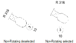
The Edit Symbol window opens, where the default position and format of the labels is specified for instruments that use this label legend. The name of the current label legend is displayed at the top of the Edit Symbol window. The instrument used for the layout is either the symbol selected in Lighting Instrument Layout Symbol or the active symbol at the time the legend was created.
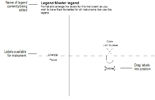
2. The labels selected for the legend display to the left of the instrument diagram. Drag each label to its position on or around the instrument. The label’s formatting can be set by selecting the label, and then using the Object Info palette or the Text menu to select the label’s font, size, style, and justification. The label stacking order can be changed with the Modify > Send commands; the instrument is part of the stacking order. Change the color of the label by selecting it and applying a solid pen color from the Attributes palette.
If necessary, the labels placed outside the bounding box of the instrument are adjusted so they are always placed at an absolute distance from the instrument. For example, a label placed six inches in front of an instrument always appears six inches in front of any instrument to which the label is applied. The position of a label placed upon an instrument is scaled so it is in the same relative position whether the instrument is larger or smaller than the one used for formatting. A label placed at the center of the instrument is always at the center.
3. When the labels are set, click Exit Symbol in the upper right corner of the window to return to the drawing. The formatting and position of the labels applies to all instruments that use this legend.
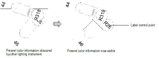
Labels should normally be repositioned through the Label Legend Manager. On a complex light plot, however, a label can be hidden by the nearest object. If that occurs, click on the instrument to select it, and then click on the instrument label control point, located at the center of the label, with the Selection tool. Drag the label to another location. This one-time repositioning does not affect the label legend.
If labels have been repositioned and the arrangement is suitable to use as a label legend for other instruments, you can create a new label legend from a selected lighting instrument’s legend. The current label arrangement and instrument rotation are used for the new label legend.
To create a label legend based on an existing instrument:
1. Select the lighting instrument. The instrument must already have a label legend attached.
2. Select Spotlight > Label Legend > Create Label Legend from Instrument.
3. Provide a unique name for the new label legend.
By default, the instrument’s existing label legend is appended with a -1 (or with the next available number) as a suggested name.
4. Click OK.
The new label legend is created, and it is automatically assigned to the selected instrument. The instrument specified in Symbol Name in the Object Info palette of the selected instrument becomes the representative lighting device for the label legend.
Label legends from another file created with the Vectorworks Spotlight product can be imported into the current file. Import the Label Legends symbol folder contents from the original file into the new file with the Import command in the Resource Browser; place the legends into the Legends folder. The imported label legends are listed in the Label Legend Manager. See “Importing a Symbol or Symbol Folder” on page 248.
~~~~~~~~~~~~~~~~~~~~~~~~~
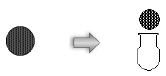
 Adding Lighting Instruments
Instruments can be inserted from the thousands of symbols provided in symbol libraries, or created as custom symbols that you convert into lighting instruments.
• In the Resource Browser, either select one of the lighting symbols from the symbol libraries or one of the symbols you have created in this file or a Favorites file. Insert the symbol with the Lighting Instrument tool to place a lighting instrument object on the light plot. This method is described in “Inserting Instruments” on page 874.
• Convert custom geometry to a lighting instrument. This method is described in “Creating a Lighting Instrument Symbol” on page 873.
The instrument symbols from the libraries included with the Vectorworks Spotlight product contain all the required attribute information. When creating or using your own symbols with the Vectorworks Spotlight product, see “Lighting Instrument Specifications” on page 889.
An existing lighting instrument with specific parameters can be saved as a red symbol (a preformatted resource).
~~~~~~~~~~~~~~~~~~~~~~~~~
 Creating
a Lighting Instrument Symbol
Creating
a Lighting Instrument Symbol The Vectorworks Spotlight product provides hundreds of lighting symbols; however, it is not necessary to use only these pre-defined symbols. Create a Spotlight instrument out of a currently selected symbol—once the symbol is converted to an instrument, the instrument functionality is present and the label legend is attached.
See “Lighting Instrument Specifications” on page 889 for more information and restrictions on using custom symbols for lighting instruments, and information on attaching the Light Info Record.
To create a lighting instrument:
1. Convert the object to a symbol by selecting Modify > Create Symbol.
Symbols can have a separate 2D and 3D representation.The lighting instrument object automatically uses the appropriate portion of the symbol. At a minimum, the symbol must have at least a 2D component; it also requires a 3D component to display correctly in 3D views. For information on symbols, see “Creating New Symbols” on page 235.
2. Select the symbol or symbols.
3. Select Spotlight > Object Conversion > Convert to Instrument.
The selected symbol is converted into a lighting instrument that remains inserted in the drawing. The active label legend, if any, is applied to the instrument(s); see “Using the Label Legend Manager” on page 868 for more information. The instrument properties can be changed through the Object Info palette; some of the instrument parameters may need to be entered.
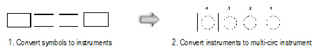
If creating multi-circuit instruments, first create each instrument’s symbol (see “Multi-circuit Instrument Specifications” on page 893). Then insert the multi-circuit instruments as described in “Instrument and Accessory Specifications” on page 889.
Select the instrument from the Resource Browser as an active symbol definition and use the Lighting Instrument tool to insert again if required (see“Inserting Instruments” on page 874).
Any instrument that has been inserted from a library or converted from a symbol can be saved as a red symbol. Its appropriate default values are retained, and when inserted from the Resource Browser, the instrument picks up the lighting position and active label legend. For more information on red symbols, see “Symbol Types” on page 233.
To create a lighting instrument resource with pre-defined parameters:
1. Select a current instrument and ensure that all its parameters have been specified as desired.
In the Object Info palette, set the Use Legend parameter to None and delete the lighting position (Position parameter). Set the Z height of the instrument to 0.
Set a label legend name to use a specific label legend, rather than the current one, upon insertion. If the label legend is not in the file at the time of symbol insertion, it is automatically imported.
2. With the instrument selected, select Modify > Create Symbol.
The Create Symbol dialog box opens. Provide a name for the new symbol. For information on symbols, see “Creating New Symbols” on page 235.
3. Select Convert to Plug-in Object, and then click OK.
4. Click OK to create the symbol.
If the Move dialog box opens, specify the location of the resource.
5. The lighting symbol is saved in the Resource Browser as a red symbol. When the symbol is inserted, it functions as a plug-in object and the saved parameters are retained.
~~~~~~~~~~~~~~~~~~~~~~~~~
 Inserting
Instruments
Inserting
Instruments Use Lighting Instrument tool to insert an existing instrument symbol. This can be a symbol that you have created, located in a Favorites file or the current file, or it can be one of the symbols imported from the libraries included with the Vectorworks Spotlight software ([Vectorworks]\Libraries); see “Resource Libraries” on page 215. When the Vectorworks Spotlight product is installed, lighting instrument symbols are also provided as default content. Default content is automatically imported into the file and displays in the Resource Browser.
For information on importing symbols, see “Accessing Existing Resources” on page 225.

To insert a lighting instrument:
1. From the Resource Browser, double-click on the instrument symbol to insert. This automatically activates the symbol and selects the Lighting Instrument tool from the Spotlight tool set.
Alternatively, select the instrument symbol from the Resource Browser and choose Resources > Make Active to make it the active symbol definition. The Lighting Instrument tool is automatically selected.
2. Click once to insert the active instrument symbol definition, and then again to determine the instrument rotation. By default, the active Label Legend is applied to the instrument.
If an instrument symbol is accidentally inserted by the Symbol Insertion tool, the instrument functionality will not be present. When correctly inserted, the Object Info palette displays “Lighting Device” for the selected instrument.
Once the Lighting Instrument tool has been selected, it remains selected by default so that instruments can be repeatedly inserted.
3. Place instruments on a lighting position to add them to that lighting position and allow auto-numbering. A different type of instrument can be placed by double-clicking on another instrument symbol definition and continuing to use the Lighting Instrument tool.
Once instruments have been inserted, they continue to automatically associate with the nearest lighting position within a specified Pick Radius set in the Spotlight preferences. To avoid instruments changing their lighting position association as they are moved, disable automatic positioning.
~~~~~~~~~~~~~~~~~~~~~~~~~
 Inserting
Multi-circuit Instruments
Inserting
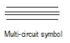
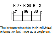
Multi-circuit Instruments Lighting instruments can be inserted as multi-circuit instruments that act as a group while retaining their individual parameters and labels.
As an example, a three-cell Cyc light consisting of different colors can be inserted as a single multi-circuit instrument that can be easily positioned. However, each light in the multi-circuit instrument retains its own information, which is displayed in its label legend. When generating paperwork, each cell of the instrument is listed individually.
The Lighting Instrument tool inserts multi-circuit instruments.
The Spotlight > Object Conversion > Convert to MultiCircuit command is no longer required when inserting multi-circuit instruments, although it is still available.

To insert a multi-circuit instrument:
1. Create a multi-circuit symbol out of instrument symbols (left, center, and right components), or locate a multi-circuit symbol in the Resource Browser.
See “Creating New Symbols” on page 235.
The multi-circuit symbol must consist only of other symbols to be properly inserted as a multi-circuit instrument. Otherwise, the Lighting Instrument tool treats it as a single circuit instrument.
2. Click the Lighting Instrument tool from the Spotlight tool set.
3. Select Resources > Make Active to make the multi-circuit symbol the active symbol definition. Alternatively, double-click on the symbol to activate it.
4. Click once to insert the active multi-circuit instrument symbol definition, and then again to determine the multi-circuit instrument rotation. By default, the active Label Legend is applied to each part of the multi-circuit instrument. The multi-circuit instrument is numbered according to the lighting position settings.
The Spotlight > Object Conversion > Convert to MultiCircuit command can add a selected instrument to the multi-circuit instrument. To undo a conversion to a multi-circuit instrument, select the multi-circuit instrument and then the Convert to MultiCircuit command.
~~~~~~~~~~~~~~~~~~~~~~~~~
 Editing Lighting Instruments
Once lighting instruments have been inserted (normally, on a lighting position), many of the parameters of one or more selected instruments can be changed from the Object Info palette and Lighting Device dialog box, and the color, numbering, alignment, and other options can be controlled.
To select all lighting instruments focused on a particular focus point, right-click (Windows) or Ctrl-click (Mac) on the focus point and select Select Focused Lighting Devices from the context menu. The focus point and any other selected objects are deselected automatically to facilitate faster editing of the lighting instrument(s).
~~~~~~~~~~~~~~~~~~~~~~~~~
 Lighting
Instrument Properties
Lighting
Instrument PropertiesInstrument (or accessory) parameters can be viewed and edited in the Object Info palette.
The parameters that display on the Shape tab of the Object Info palette depend on the settings made in Spotlight preferences; see “Specifying Lighting Device Parameter Display” on page 95.
Double-click on a lighting device, or click Edit from the Object Info palette or the context menu of one or more selected devices. The Lighting Device dialog box opens, facilitating instrument parameter modifications; see “Changing Instrument Properties” on page 879. Advanced light properties, which include turning the associated light source on, are available by editing the light source embedded within the instrument; see “Advanced Light Properties” on page 880.
For a custom instrument symbol without an information record attached, enter the required instrument object parameters (see “Attaching the Light Info Record and Light Info Record M” on page 892). An entry is not required for every field.
Click to show/hide the parameters.
For instruments and accessories, do not provide a name on the Data tab. The instrument or accessory Unique ID Number (UID) is automatically entered and must be used as the instrument or accessory name.
~~~~~~~~~~~~~~~~~~~~~~~~~
 Changing
Instrument Properties
Changing
Instrument Properties To edit the properties of a lighting instrument (or accessory):
1. Select one or more lighting instruments.
2. From the Object Info palette or the context menu, select Edit, or simply double-click a single instrument selection.
The Lighting Device dialog box opens. The lighting device parameters are described in “Lighting Instrument Properties” on page 876. Only the parameters which are different are described here.
Click to show/hide the parameters.
3. Click the Light Information tab.
Click to show/hide the parameters.
4. Click the Shutters tab to set the shutter cut information.
Specify the depth and angles for the top, left, right, and/or bottom shutters. Each shutter is located at 90º intervals around the lighting instrument, and can be adjusted +/- 45º. The shutter depth ranges from 0 to 100%, with 100% cutting through the center of the light source.
5. Click the User Data tab to edit user field value information.
User data fields and any default values display here and the default values can be edited by selecting a field name and entering the new value in Value.
6. Click OK to apply the changes to the selection.
The properties of one or more selected devices or objects can also be edited from the Shape tab of the Object Info palette (see “Lighting Instrument Properties” on page 876).
A selected lighting device or a selection of devices can be cut, copied, and pasted with the Edit menu commands. See “Editing Objects” on page 995 for more information on the basic editing commands.
~~~~~~~~~~~~~~~~~~~~~~~~~
 Advanced
Light Properties
Advanced
Light Properties More advanced control over the lighting instrument properties is possible by editing the light source embedded within the instrument. Turn the lighting instrument on and off by editing the embedded light.
To edit the embedded light source:
1. Select the lighting instrument(s).
2. From the lighting instrument context menu, select Edit Light.
The Light Properties dialog box opens. These parameters offer full control over the light source, and are described in “Light Source Properties” on page 1574. The Renderworks product is required for certain parameters.
Various light parameters are disabled, because they are controlled by the lighting device object instead.
Select a light Kind of Custom to associate a light distribution file with the light. Note that light distribution files and theatrical lighting manufacturers may not specify output in the same way.
3. To enable the light properties, turn the light on in the Properties dialog box or from the Visualization palette, or right-click (Windows) or Ctrl-click (Mac) on the instrument and select Turn On from the context menu.
~~~~~~~~~~~~~~~~~~~~~~~~~
 Lighting
Instrument Color
Lighting
Instrument ColorThe gel color of a lighting instrument is specified by the Color parameter in the Object Info palette or Lighting Device dialog box. Define the color by one of these methods.
• RGB values separated by commas (such as 191, 49, 26); values must be between 0 and 255
• Manufacturer color codes, by manufacturer name or abbreviation and color number (such as Gam 650, G 650, G-650, or G650)
• Name of the color as specified in the file’s color palettes (see “Applying Colors” on page 1130)
• Web hex values prefixed by the pound sign (such as #003366)
• Combinations of two or more colors (such as R46+R10); the resultant calculated color combination displays, just as when combining actual color filters. Invalid single colors are treated as white when calculating color combinations.
Acceptable manufacturer names and abbreviations are shown in the following table.
Manufacturer |
Product Name |
Abbreviation |
|---|---|---|
Rosco |
Roscolux |
R, X |
Rosco |
Supergel |
R, S, RS |
Rosco |
E-Color |
E, RE |
Rosco |
CalColor |
R, RC |
Rosco |
Cinegel |
R, RCG |
Rosco |
Cinelux |
R, RCL |
Rosco |
Storaro |
R, RSO |
Lee Filter |
Lee |
L |
Gam |
Gam |
G |
Apollo |
Apollo |
A, AP |
GoboMan |
GoboMan |
GM |
To draw a colored light beam for the lighting instrument, see “Drawing Light Beam Representations” on page 899.
The color setting can affect the display of the lighting device color, depending on the Spotlight preferences. See “Lighting Device Setup” on page 92.
~~~~~~~~~~~~~~~~~~~~~~~~~
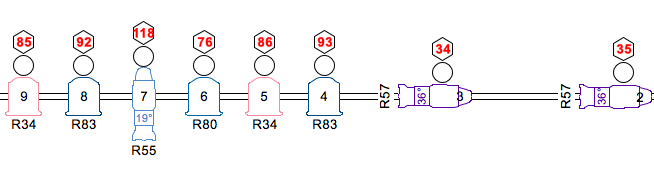
 Instrument
Numbering
Instrument
Numbering Instruments can be numbered automatically according to lighting position order, or manually according to specified settings.
Instruments can numbered according to the lighting position automatic numbering parameters).
To automatically number the instruments on a lighting position:
1. Select the lighting position.
2. From the Object Info palette, specify the Starting Number, Increment, Numbering Direction, and, for multi-circuit instruments, the Multi-Circuit Numbering.
3. Click Auto Number.
The instruments are automatically numbered. The Unit Number in the Object Info palette of a selected lighting instrument displays its number, which can be changed to override the automatic number.
To display the numbers on the drawing, specify a label legend that includes the Unit Number in the label. See “Setting Up Instrument Label Legends” on page 867.
To automatically number all instruments assigned to a lighting position:
Select Spotlight > Auto Number Positions to globally automatically number the lighting instruments in the drawing based on the settings in each lighting position.
If lighting positions are selected when the command is activated, only the instruments on the selected lighting positions are numbered.
~~~~~~~~~~~~~~~~~~~~~~~~~
 Numbering
Instruments Manually
Numbering
Instruments Manually Instruments do not have to be numbered according to the lighting position’s automatic numbering feature. The Number Instruments command provides a method of numbering instruments by unit number and other parameters that automatically increment. In addition, the command can automatically increment several other instrument parameter fields.
To number selected instruments manually:
1. Select the instrument(s) to be numbered.
2. Select Spotlight > Number Instruments.
The Number Instruments dialog box opens.
Click to show/hide the parameters.
3. Click OK.
The selected instruments are numbered, and any fields automatically specified, in the selected direction.
To number instruments manually in the order they are selected:
1. Select Spotlight > Number Instruments.
2. Specify the field and numbering parameters as described in “Numbering Selected Instruments” on page 882.
3. In the Direction list, select Manual (the manual direction is selected automatically if no instruments were selected).
4. Click OK, and click the instruments to be numbered one by one. To stop numbering instruments, click in an empty area of the drawing.
~~~~~~~~~~~~~~~~~~~~~~~~~
 Replacing
Instruments
Replacing
Instruments An individual instrument can be replaced by another type of instrument by choosing the new active symbol in the Resource Browser, and then selecting Replace with Active Symbol in the Object Info palette.
However, this process would be time-consuming for multiple instruments. By using the Replace Instrument command, all the instruments of a particular type can easily be replaced with another type of instrument. Alternatively, a selection of instruments can be replaced with another type of instrument.
To replace all the instruments of one type:
1. Select Spotlight > Replace Instrument.
The Replace Instruments dialog box opens.
2. Click Replace All, and then specify the instrument type to be replaced by selecting it from the list.
3. In the Symbol Folders list, select the location of the replacement instrument type. Select the specific instrument type from the Symbols list.
4. Click OK. All instruments of the type specified are replaced with the selected instrument type.
To replace selected instruments:
1. Select the instruments to be replaced.
2. Select Spotlight > Replace Instrument.
The Replace Instruments dialog box opens.
3. Click Replace selected instruments.
4. Specify the location of the replacement instrument type in the Symbol Folders list. Select the specific instrument type from the Symbols list.
5. Click OK. The selected instruments are replaced with the specified instrument type.
~~~~~~~~~~~~~~~~~~~~~~~~~
 Changing
the Instrument Label Legend
Changing
the Instrument Label Legend As instruments are placed on the light plot, the active label legend is assigned to them by default. However, the legend can be changed for a selection of instruments.
To change the instrument label legend:
1. Select one or more instruments.
2. Click on the Spotlight > Label Legend > Assign Legend to Instruments command.
The Assign Legend to Instruments command is also available from the object context menu for selected instruments. Right-click (Windows) or Ctrl-click (Mac) to quickly access the command.
The Assign Legend to Instruments dialog box opens.
3. Select the new label legend for the instruments.
4. Click OK; the new label legend is applied to the selection.
The label legend can also be changed for an individual instrument by selecting the instrument, and then selecting the legend name from the Use Legend list in the Object Info palette.
Use the Find and Modify command to quickly generate a custom selection of specific instruments and apply the new legend to the selected instruments (see “Find and Modify” on page 886).
~~~~~~~~~~~~~~~~~~~~~~~~~
 Refreshing
Instrument and Light Position Data
Refreshing
Instrument and Light Position Data The Spotlight > Refresh Instruments command updates light position information and instrument labels to reflect any changes that have been made. This ensures that all current data is displayed; it is a good idea to select this command before printing the light plot.
Two-fers do not get updated with the instrument information when the Refresh Instruments command is selected.
The Refresh Instruments command is also available from the document or object context menu. Right-click (Windows) or Ctrl-click (Mac) to quickly access the command.
~~~~~~~~~~~~~~~~~~~~~~~~~
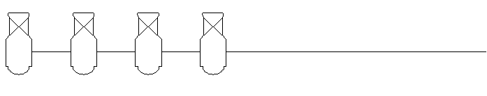
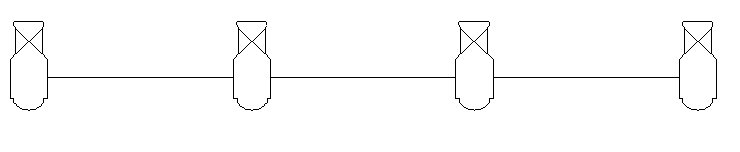
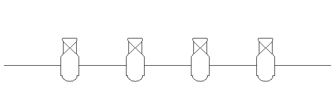
 Aligning
Instruments
Aligning
Instruments Lighting instruments can be automatically aligned and distributed along a specified guide line with the Align and Distribute Items tool.

To align and/or distribute instruments along a line:
1. Select the objects to be aligned or distributed.
2. Click the Align and Distribute Items tool from the Spotlight tool set.
3. Click to define the beginning of the guide line, and click to end.
The Align and Distribute dialog box opens.
The instruments can be aligned and distributed according to several options.
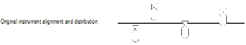
Click to show/hide the parameters.
4. Click OK to align or distribute the instruments according to the selected option.
~~~~~~~~~~~~~~~~~~~~~~~~~
 Find
and Modify
Find
and Modify Custom selection criteria can be defined to quickly and easily search for instruments, lighting positions, and accessories and to perform an action upon the search results.
To find and modify objects:
1. Select Spotlight > Find and Modify.
The Find and Modify dialog box opens.
2. Select the type of object to be searched and specify the change(s) to occur to the items found.
Click to show/hide the parameters.
3. Once the find and modify criteria have been defined and action(s) specified, click OK. The selected change(s) will occur to the items located by the search.
~~~~~~~~~~~~~~~~~~~~~~~~~
 Adding
Accessories
Adding
AccessoriesAccessories can be inserted from the many symbols provided in symbol libraries, or created as custom symbols that you convert into accessories.
• In the Resource Browser, either select one of the accessory symbols from the existing symbol libraries or one of the symbols you have created in this file or a Favorites file. Insert the symbol with the Lighting Accessory tool to place the accessory object on the light plot. This method is described in “Inserting Accessories” on page 888.
• Convert custom geometry into an accessory. This method is described in “Creating an Accessory” on page 887.
The accessory symbols from the libraries included with the Vectorworks Spotlight product include all the required attribute information and have the correct accessory type assigned (Accessory or Static Accessory). To create or use your own symbols, see “Accessory Specifications” on page 893.
Lighting instrument accessories, such as color frames, barn doors, and top hats, are placed on the same design layer as the instruments. Accessories such as color frames, barn doors, and top hats have a Device Type of Static Accessory. Accessories that require a control channel, such as color scrollers, have a Device Type of Accessory.
An instrument can have multiple accessories in the same location (most accessories are placed at the front of an instrument). It can also have several accessories in different locations. Once an accessory has been associated with an instrument, the instrument controls the accessory.
~~~~~~~~~~~~~~~~~~~~~~~~~
 Creating an Accessory
 The Vectorworks Spotlight product provides accessory symbols; however, it is not necessary to use only the pre-defined symbols. Create an accessory out of a currently selected symbol—once the symbol is converted to an accessory, the accessory functionality is present. See “Accessory Specifications” on page 893 for restrictions on using symbols for accessories.
To create an accessory:
1. Draw the accessory, and then convert the object to a symbol by selecting Modify > Create Symbol.
Symbols can have a separate 2D and 3D representation. The accessory object automatically uses the appropriate portion of the symbol. At a minimum, the symbol must have at least a 2D component; it also requires a 3D component to display correctly in 3D views. For information on symbols, see “Creating New Symbols” on page 235.
2. Select the symbol(s).
3. Select the lighting instrument to associate with the accessory or accessories.
Only one instrument can be selected.
4. Select Spotlight > Object Conversion > Convert to Accessory.
The selected symbol is converted into an accessory and remains inserted in the drawing. It is associated with the selected lighting instrument. The accessory properties can be changed through the Object Info palette; some of the accessory information may need to be entered.
Accessories such as color frames, barn doors, and top hats should have a Device Type of Static Accessory. Accessories that require a control channel, such as color scrollers, should have a Device Type of Accessory.
Select the accessory from the Resource Browser as an active symbol definition and use the Lighting Accessory tool to insert it again if required (see “Inserting Accessories” on page 888).
To associate an accessory with a different lighting instrument, or associate an accessory that was never properly associated, select the accessory and the instrument to associate, and then select Spotlight > Object Conversion > Convert to Accessory.
~~~~~~~~~~~~~~~~~~~~~~~~~
 Inserting Accessories
 Existing accessory symbols are inserted with the Lighting Accessory tool. This can be a symbol that you have created, located in a Favorites file or the current file, or it can be one of the symbols imported from the libraries included with the Vectorworks Spotlight software ([Vectorworks]\Libraries); see “Resource Libraries” on page 215.
For more information on importing symbols, see “Importing a Symbol or Symbol Folder” on page 248.

To insert an accessory:
1. From the Resource Browser, double-click on the accessory symbol to insert. This automatically activates the symbol and selects the Lighting Accessory tool from the Spotlight tool set.
Alternatively, select the accessory symbol from the Resource Browser and choose Resources > Make Active to make it the active symbol definition. The Lighting Accessory tool is automatically selected.
2. Click once to insert the active accessory symbol definition, and then again to determine the accessory rotation. The cursor changes to a bull’s eye. Click on the instrument which will be associated with the accessory.
Because the accessory is controlled by the associated instrument, the items move together. However, an accessory can be positioned on its own by selecting it and dragging.
If an accessory symbol is accidentally inserted by the Symbol Insertion tool, the accessory functionality will not be present. If correctly inserted, the Object Info palette displays “Lighting Device” (with a Device Type of Accessory or Static Accessory) for the selected accessory.
Once the Lighting Accessory tool has been selected, it remains selected by default so that accessories can be repeatedly inserted. To place non-instrument symbols after placing accessories, switch to the Symbol Insertion tool.
The accessory Object Info palette parameters are nearly identical to those of an instrument, because it requires many of the same parameters. The Device Type is Static Accessory or Accessory.
Entering a parameter in the accessory Object Info palette will not change the associated instrument parameters.
For more information on the Object Info palette parameters, see “Lighting Instrument Properties” on page 876.
When a lighting instrument is deleted, its associated accessory is also deleted.
~~~~~~~~~~~~~~~~~~~~~~~~~
 Instrument
and Accessory Specifications
Instrument
and Accessory SpecificationsIn the Vectorworks Spotlight product, custom symbols can be created and used in addition to the pre-defined standard symbol sets. Create an instrument, accessory, or lighting position out of a currently selected symbol by converting it with the commands in the Spotlight menu.
Certain rules apply when creating lighting and accessory symbols.
~~~~~~~~~~~~~~~~~~~~~~~~~
 Lighting
Instrument Specifications
Lighting
Instrument SpecificationsSpecial rules apply when creating a symbol to be converted to a lighting instrument.
Symbols should be hybrid (2D/3D) so that they display properly in both 2D and 3D views. At a minimum, the symbol must contain a 2D component, which must be a screen plane representation and not a 2D planar object.
Create the 2D view of the symbol using as few polygons and lines as possible. If possible, use a single polyline rather than individual line segments. All instruments should be drawn with the front of the instrument (the end which emits light) oriented towards the top of the drawing. The symbol below was created from these few constituent parts:
The line weight of the symbol is also a consideration; the instruments need to stand out when printed. The outer perimeter of the symbol should have a line weight of at least 1/2 point (7 mils). Interior details should use a lighter line weight.
The 2D representation should have a solid fill so that it obscures information under the symbol. The size of the instrument should be accurate based on the real instrument it represents. While drawing the instrument, keep the level of detail as minimal as possible. The goal is to be able to distinguish instruments from one another, not to create a detailed plan view of each instrument.
For instruments with multiple configurations, it is acceptable to use simple graphical differences to distinguish among the models. For example, use the following variations to separate the different versions of a symbol:
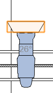
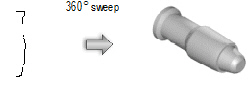
The 3D portion of the instrument should be drawn as if it is hung straight down (along the Z-axis) with the yoke oriented along the Y-axis. The top of the instrument should be oriented towards the top of the drawing. An easy way to generate a reasonable 3D instrument body is to sweep the 2D portion of the symbol. The segment angle of the sweep should be between 20 and 40°. See “Varredura” on page 1040 for more information.
Keep the 3D symbol simple. It should be solid. The model should be accurately sized, but without minute details like handles, grommets, fins, louvers, cords, and knobs. These items can add significantly to the rendering time required, and are not necessary to distinguish among instruments.
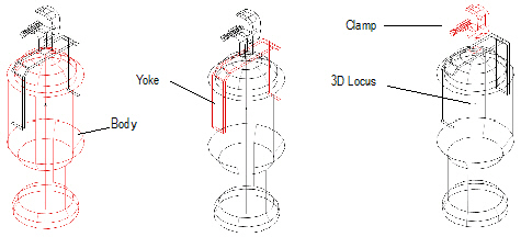
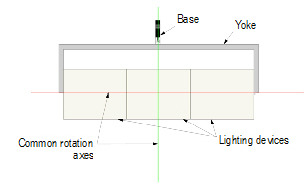
The 3D model should consist of three parts: the body, a yoke, and a clamp or base. Any subparts should be made into a single object or group for each of these pieces. The body represents the part of the instrument where light is emitted; the yoke connects the body to the base, and the base consists of either a base motor unit for moving lights or a clamp or other hanging device for other lights. The clamp can be imported from the symbol library provided with the Spotlight program. Place a 3D locus within the body of the instrument.
All the parts should be aligned as shown; the yoke rotates about the Z-axis, and the body rotates at the height of the locus point.
Align the 2D and 3D views so that the hanging points of both versions line up.
The insertion point of the 2D/3D hybrid symbol in Top/Plan view should represent the hanging location of the instrument. The 3D insertion point should be the hanging point (center of the clamp or base).
Create the symbol as described in “Creating New Symbols” on page 235.
Attach the Parts record to each of the three pieces of the 3D instrument model: body, yoke, and base or clamp.
To attach the Parts record:
1. In the Resource Browser, import the Parts record from one of the instrument library files included with the Spotlight program.
Locate the record and select Resources > Import to bring the record into the current file.
2. Select the new symbol, and select Modify > Edit Symbol.
3. In the Edit Symbol window, select the body, yoke, or base/clamp.
4. Click on the Data tab in the Object Info palette. Attach the Parts record to the part by selecting the check box.
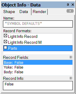
5. Edit the record by selecting the appropriate record field and changing its value to True. For example, select the yoke, attach the Parts record, and change the Yoke record field to True.
6. Repeat steps 3 – 5 for each of the three parts of the instrument model.
7. Click Exit Symbol at the upper right corner of the window to return to the drawing.
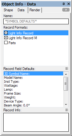
Attach the Light Info record to the lighting instrument symbol, with field names that match the names of the fields in the instrument object. Not all the fields are required, but the desired fields for the instrument object to read should be included. Filling the instrument type field with the manufacturer’s name and model name for the particular instrument is recommended.
The Light Info M record provides metric measurements of the weight and frame size of the instrument object. This is needed for instruments that could be used in either imperial and metric drawings.
To attach the light info record:
1. In the Resource Browser, import the Light Info Record and Light Info Record M from one of the instrument library files included with the Spotlight program.
Locate the records and select Resources > Import to bring the records into the current file.
2. Select the new symbol, and select Modify > Edit Symbol.
3. In the Edit Symbol window, click on an empty location so that nothing is selected.
4. Click on the Data tab in the Object Info palette. Attach the Light Info Record and Light Info Record M to the symbol defaults by selecting the check boxes. Then edit the records by selecting the record field and entering its record information.
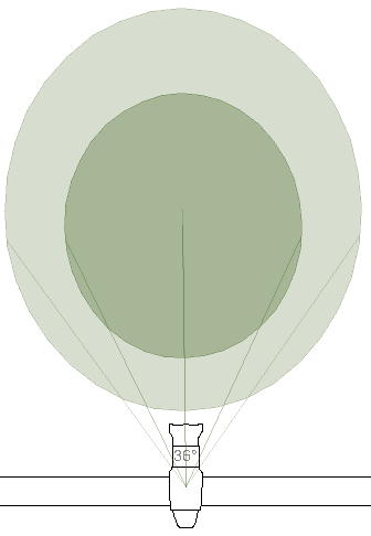
The Candlepower, Beam Angle, and Field Angle parameters affect the photometric grid and photometer object calculations. The Beam Angle and Field Angle parameters affect the Draw Beam feature.
Normally, do not include text labels with the instrument, as these are handled by the instrument object. An exception can be made to distinguish different models or lamps of an instrument. For example, create three versions of a single PAR64 symbol by adding MFL, WFL, and NSP text blocks.
Symbols should be named with the model name of the lighting instrument.
5. Turning the lighting instrument’s light on in the Visualization palette includes a spot light as part of the lighting instrument. While editing the symbol, the spot light can be added, and accurate lighting information specified with the parameters in Use Emitter. See “Adding Light Sources” on page 1570 for information on adding a spot light and setting accurate lighting parameters.
6. Click Exit Symbol at the upper right corner of the window to return to the drawing.
As an alternative to the process of manually editing the symbol definition to attach the Light Info (and/or Light Info M) record, use the Lighting Symbol Maintenance command as described in “Lighting Symbol Maintenance” on page 959. Add the symbol by clicking New, and the Light Info record is automatically attached to it. Once in the maintenance list, the record data can be easily edited.
~~~~~~~~~~~~~~~~~~~~~~~~~
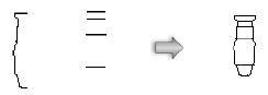
 Multi-circuit
Instrument Specifications
Multi-circuit
Instrument SpecificationsMulti-circuit instruments represent a special case of the instrument object. Each symbol drawn should represent a single element of the multi-circuit instrument. An instrument that is at the end of the multi-circuit strip should look different from the instruments that are in the center. Place the number of symbols required to create the multi-circuit instrument. For example, place four symbols (two ends and two middle) to create a four-circuit cyc unit.
The multi-circuit symbol must consist only of other symbols to be properly inserted as a multi-circuit instrument. Otherwise, the Lighting Instrument tool treats it as a single circuit instrument.
Attach the light info record to the individual instruments within the multi-circuit unit by the same method as for an individual lighting instrument.
The multi-circuit lighting device focuses in 3D in the same way as individual lighting devices (see “Lighting Instrument Specifications” on page 889). The yoke is created from portions of the individual instrument symbols. The 3D locus, placed within the container multi-circuit symbol, is used as a common rotation axis for the entire multi-circuit unit.
~~~~~~~~~~~~~~~~~~~~~~~~~
 Accessory
Specifications
Accessory
SpecificationsThe accessory symbol should be a 2D/3D hybrid object. At a minimum, the symbol must contain a 2D screen representation. Keep the accessory representation as simple as possible to reduce rendering time.
The 3D portion of the accessory should be drawn as if it is hung straight down (along the Z-axis). The top of the accessory should be oriented towards the top of the drawing. 3D geometry should be drawn below the Z-axis to properly align with the front of the lighting instrument.
The Object Info palette for accessories and lighting instruments looks identical, but the Device Type differs for accessories (Accessory or Static Accessory).
Accessories should have a record attached for storing the default accessory values. The record should not contain fields that vary from instance to instance of an accessory. For example, do not add a Color Scroller channel field value unless that channel is used by all the color scrollers in the file.
The attached record should consist of the following fields:
Field |
Description |
|---|---|
Instrument type |
Accessory name; this can be a specific manufacturer’s model name or number, or a generic name for the accessory, such as 6” Top Hat |
Accessory type |
Generic accessory category; in some cases, this can be similar, or identical to the instrument type (example accessory types include Top Hat, Barn Door, Color Scroller, Gobo Rotator, and Color Frame) |
Wattage |
Amount of power consumed by the accessory |
Weight |
Accessory weight |
Other |
Add fields as desired; these fields are read into the Lighting Device object if the field name in the accessory record matches the field name of the Lighting Device object |
A Parts record is not required for an accessory.
~~~~~~~~~~~~~~~~~~~~~~~~~
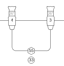
 Ganging Instruments
 Two-fers gang two or more instruments together on one circuit, dimmer, channel, or dimmer and channel.
The ganging field parameter value(s) should match. If not, the value(s) from the first selected instrument are used.

To gang two or more instruments:
1. Click the Ganging tool from the Spotlight tool set.
Click Preferences from the Tool bar to set the default tool preferences, if desired.
2. Click on the first, and then the second, instrument to be ganged together. If more than two instruments are to be ganged together, continue clicking on each instrument in succession.
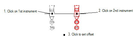
3. Click to set the offset distance of the two-fer label.
If the field values of the instruments do not match, confirm that this is acceptable in the Notice dialog box which opens.
4. Click OK. The instruments are ganged together with one or more two-fer objects.
The properties of a two-fer are displayed, and can be edited, in the Object Info palette.
Click to show/hide the parameters.
~~~~~~~~~~~~~~~~~~~~~~~~~