Inserindo
Informações de Georreferenciamento para o Documento
Inserindo
Informações de Georreferenciamento para o DocumentoNo Vectorworks Architect, existem vários recursos para importação e exportação de dados GIS (Sistema de Informação Geográfica), e para georreferenciamento de desenhos Vectorworks.
Para um projeto de arquitetura ou paisagismo em pequena escala, você pode querer importar com precisão informações relacionadas ao local do projeto, tais como limites de propriedade ou recursos de utilidade municipais.
Para um projeto em escala maior, você pode importar vários "shapefiles" e arquivos de imagem e organizá-los em mapas, acrescentando cores, símbolos e notas com base em informações do banco de dados. Você pode, em seguida, exportar arquivos para uso em outro software GIS.
Tanto o Vectorworks Architect como o Vectorworks Landmark podem armazenar informações de georreferenciamento para as camadas de projeto, assim como importar e exportar informações de georreferenciamento relacionadas com arquivos SHP (shapefiles) e arquivos de imagem. O produto Vectorworks Landmark tem recursos adicionais para tornar as operações de GIS mais fáceis, incluindo ferramentas para adicionar gratículas e grandes círculos a um desenho.
Clique aqui para obter uma dica de vídeo sobre este tópico (necessário acesso à Internet).
~~~~~~~~~~~~~~~~~~~~~~~~~
Inserindo
Informações de Georreferenciamento para o DocumentoOpções de georreferenciamento são complexas; o que funciona para fluxos de trabalho de arquitetura pode não ser adequado para fluxos de trabalho de GIS. Diferentes regiões da Terra têm diferentes exigências geográficas.
Uma vez que a Terra não é uma esfera perfeita, não é um processo simples projetar um mapa sobre a superfície da terra, ou ainda transferir um objeto sobre sua superfície. As projeções são fórmulas matemáticas que traduzem a forma da terra para uma página 2D. Porque a tradução perde dados, diferentes projeções representam as coordenadas longitudinais e latitudinais da esfera não-uniforme para a página.
Quando o georreferenciamento está ativado, cada camada de projeto armazena informações que descrevem o mapeamento do sistema de coordenadas cartesianas da camada em um sistema geográfico de coordenadas em latitude e longitude. O deslocamento da origem determina como a projeção relaciona-se com a origem interna (o centro do desenho no arquivo Vectorworks); esse deslocamento pode ser desligado no nível do documento ou ao nível da camada para fluxos de trabalho de GIS.
Se todas, ou a maioria, das camadas de projeto terão a mesma informação de georreferenciamento, use o comando Georreferenciamento para definir os parâmetros para o documento. Depois que o padrão de georreferenciamento esteja definido, edite cada camada do projeto para ativar o georreferenciamento, e para personalizar as configurações para camadas individuais, se necessário.
Camadas sem georreferenciamento assumem como estando na projeção Equirectangular, que mapeia latitude e longitude directamente sobre o eixo XY. A origem representará 0 °, 0 °, e a escala será igual ao da escala de latitude e longitude no Equador da Terra. Algumas ferramentas de georreferenciamento não funcionam adequadamente em camadas de projeto que não são georreferenciados.
Para definir o georreferenciamento de um documento:
1. Selecione Arquivo > Ajustes do Documento > Georreferenciamento. A caixa de diálogo Georreferenciamento do Documento abrirá.
Clique para mostrar / ocultar os parâmetros.
2. Clique em OK para salvar as configurações de georreferenciamento.
3. Ative georreferenciamento para cada camada de projeto que requeira isto, conforme descrito em “Inserindo informações de Georreferenciamento em uma camada de projeto.” na página 774.
 Inserindo
informações de Georreferenciamento em uma camada de projeto.
Inserindo
informações de Georreferenciamento em uma camada de projeto.Use a janela de diálogo Editar Camadas de Projeto para ativar o georreferenciamento para as camadas que irão utilizar esta informação. As opções definidas aqui irão substituir as opções de georreferenciamento definidas para o documento. Uma vez você tenha uma camada de projeto georreferenciada, você poderá importar arquivos georreferenciados para ela, assim como exportar imagens ou shapefiles que possui informações de georeferenciamento.
To accurately measure items on a georeferenced design layer, use the Great Circle tool (from the Site Planning tool set), instead of the dimension tools from the Dims/Notes tool set. See “Creating a Great Circle” na página 779.
To enable georeferencing for a design layer:
1. Select Tools > Organization to open the Organization dialog box. From the Design Layers tab, select the layer(s) to be changed, and click Edit.
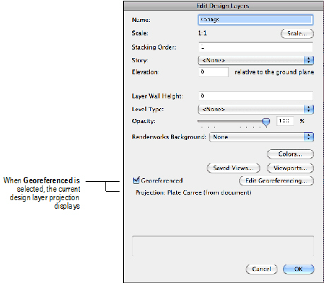
2. From the Edit Design Layers dialog box, select Georeferenced. The current projection for the layer displays below that field; the default is the current projection setting for the document.
3. To edit the georeferencing information, click Edit Georeferencing.
The Georeferencing dialog box opens, from which you can choose either to use the same settings used for the document overall, or to enter custom settings. If you choose to use custom settings for this design layer, enter the remaining fields as described for the Document Georeferencing dialog box.
When your entries are complete, click OK to save the settings and return to the Edit Design Layers dialog box.
Click to show/hide the parameters.
4. Click OK to enable georeferencing for the design layer. The selected projection displays in the Organization dialog box.
~~~~~~~~~~~~~~~~~~~~~~~~~
 Replacing
Objects with Symbols
Replacing
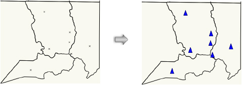
Objects with SymbolsThe Replace with Symbol command converts a selected object into a specified symbol. The symbol can use the records provided with the original object, the records associated with the replacement symbol, or both. If an imported shapefile (Vectorworks Architect or Landmark required) contains data markers that indicate the location of certain types of objects, you can convert the markers into a symbol that better suits your drawing.
To replace an object with a symbol:
1. Select the object(s) to be replaced.
2. Select Modify > Convert > Replace with Symbol.
3. The Choose a Symbol dialog box opens.
4. Select a symbol, and then select whether to use the original object records and the replacement symbol records.
5. Click OK, and then confirm that you want to replace all selected objects.
~~~~~~~~~~~~~~~~~~~~~~~~~
 Moving
an Object to a Specific Location
Moving
an Object to a Specific LocationIn the Vectorworks Landmark product, you can move an object in a georeferenced file to a different geographic location.
To move an object geographically:
1. Select the object(s) to be moved.
2. Select Modify > Move > Move Geographic.
The Move Geographic dialog box opens.
Click to show/hide the parameters.
3. Click OK to move the object(s).
~~~~~~~~~~~~~~~~~~~~~~~~~
 Creating a Graticule
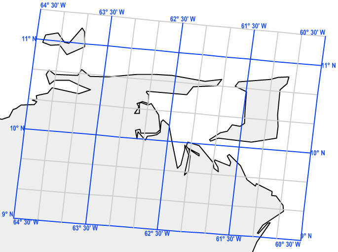
In the Vectorworks Landmark product, use the Graticule tool to place a reference grid object over the drawing. Unlike a grid that is based on X and Y coordinates, the graticule lines are based on longitude and latitude lines that are inferred from the layer projection.
Mode |
Description |
|---|---|
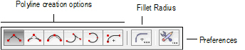
Polyline creation options |
Selects the method for drawing the polyline that will bound the graticule object; see “Creating Polylines” on page 294. |
Fillet Radius |
If the Arc Vertex mode is selected, specifies the fillet radius to use |
Preferences |
Sets the default parameters to be used for the tool |

To create a graticule:
1. From the Site Planning tool set, select the Graticule tool.
2. From the Tool bar, click the Preferences button.
The Graticule Properties dialog box opens.
Click to show/hide the parameters.
3. Click OK to save the default graticule settings.
4. From the Tool bar, select the type of polyline to use as the boundary for the graticule.
5. Click on the drawing to create the polyline boundary in the approximate location of the latitude and longitude lines you specified. Make the polyline larger than the graticule will be, so the graticule will not be cut by the polyline. When you complete the polyline, a graticule object is created over the specified location.
The Vectorworks software automatically calculates the minimum and maximum values for the latitude and longitude using the geometry and location of the defined polyline. These values can be edited later in the Object Info palette.
~~~~~~~~~~~~~~~~~~~~~~~~~
 Creating
a Great Circle
Creating
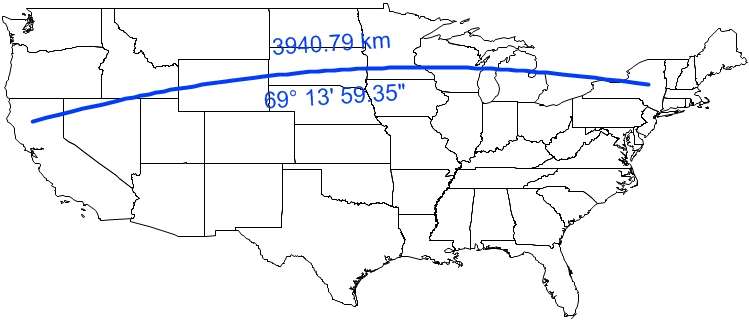
a Great CircleIn the Vectorworks Landmark product, use the Great Circle tool to place a great circle object over the drawing. Unlike a 2D dimension that shows the linear distance between X and Y coordinates in 2D, a great circle is an arc that shows the shortest distance between two points on the sphere-shaped Earth. Use the Great Circle tool (instead of a 2D dimension tool) to measure distances in a georeferenced drawing.
Mode |
Description |
|---|---|
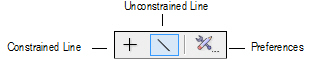
Constrained Line |
Constrains the line to be vertical, horizontal, and 30° or 45° from vertical or horizontal in any direction |
Unconstrained Line |
Draws the line at any angle Press and hold the Shift key to snap the line to predetermined angles |
Preferences |
Sets the default parameters to be used for the tool |

To create a great circle:
1. From the Site Planning tool set, select the Great Circle tool.
2. From the Tool bar, click the Preferences button.
The Great Circle Properties dialog box opens.
Click to show/hide the parameters.
3. Click OK to save the default great circle settings.
4. From the Tool bar, select whether to use the Constrained Line or Unconstrained Line mode when drawing the great circle.
5. Click on the drawing at the beginning point of the great circle, and click again at the ending point to create the object.
~~~~~~~~~~~~~~~~~~~~~~~~~
 Projection Options
For the Vectorworks Landmark product, there are several options for the type of geographic projection to use for georeferenced design layers. The Vectorworks Architect product has fewer options, because projection is generally less important for drawings on an architectural scale. For larger maps drawn with the Vectorworks Landmark product, however, the proper projection can be very important.
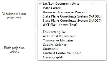
On the Document Georeferencing and the Georeferencing dialog boxes, the projections at the top of the Projection list are variations based upon the basic types, which display at the bottom of the list. For example, the Plate Carrée option is based upon the Equirectangular projection. The following table describes the basic projection types.
Projection Type |
Description |
|---|---|
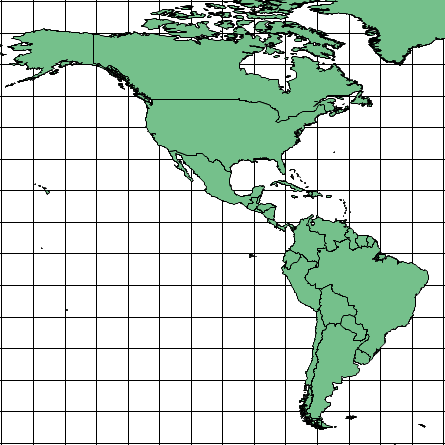
Equirectangular |
Simplest projection, good for maps of the entire world. Latitude and longitude lines are straight and equally spaced. The Lat/Lon Document Units projection is Equirectangular, centered around the equator and prime meridian, and scaled such that one document unit represents one degree of latitude and longitude. The Plate Carrée projection is Equirectangular, centered around the equator and prime meridian, and scaled in real-world units.
|
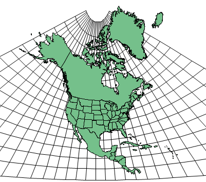
Azimuthal Equidistant |
Good for areas centered around a given point, roughly equal in height and width. Straight lines drawn from the center point represent the accurate geographic distance.
|
Transverse Mercator |
Excellent for mapping narrow (north-south) areas around a chosen longitude. Very great distortion farther east and west. Center longitude defines the chosen meridian; center latitude should be close to the area being mapped. Scale should be 1 or close to it (for example .9996). The Universal Transverse Mercator projection is Transverse Mercator defined by 6° longitude zones. In the US State Plane Coordinate System (SPCS) projections, most US state zones are either Transverse Mercator or Lambert Conformal Conic, depending on the shape of the state and its zones. There are two systems, based on two different North American Datums: NAD27 (now obsolete) and NAD83 (the current standard).
|
Cassini-Soldner |
Good for mapping narrow (north-south) areas around the central longitude. Distorts shapes farther east and west.
|
Gnomonic |
Good for navigational maps and small areas around a chosen point. All straight lines represent great circles (shortest geographical distance).
|
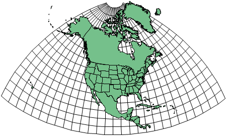
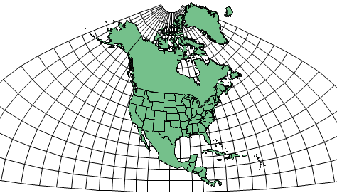
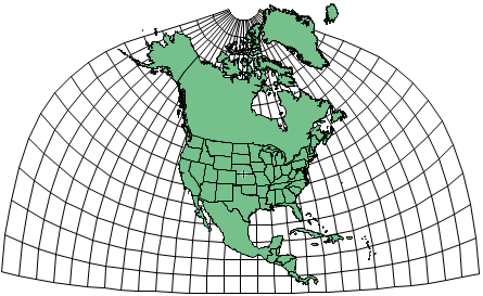
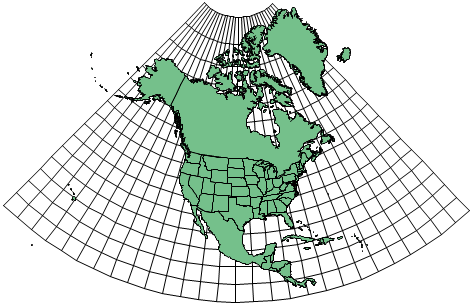
Lambert Conformal Conic |
Good for mapping wide (east-west) areas between chosen parallels. Distortion increases farther from the chosen parallels. In the US State Plane Coordinate System (SPCS) projections, most US state zones are either Transverse Mercator or Lambert Conformal Conic, depending on the shape of the state and its zones. There are two systems, based on two different North American Datums: NAD27 (now obsolete) and NAD83 (the current standard).
|
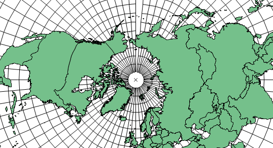
Stereographic |
Good for mapping polar areas. Parameters define the center point, which is 90 latitude for the North Pole or -90 latitude for the South Pole. Other points can be used. Scale should be 1 or very close to it (for example .9996).
|
~~~~~~~~~~~~~~~~~~~~~~~~~