Edit the properties of selected straight or round walls and their components, as well as curtain walls (Vectorworks Architect or Landmark required), in the Object Info palette. To change the wall attributes, use the Attributes palette. Certain parameters are available for standard walls or for curtain walls only. Settings on the Render tab (Renderworks required) are not available for curtain walls, since the textures of frames and panels are specified separately. Curtain walls use the Edit Curtain Wall tool to adjust the frames and panels.
Click to show/hide the parameters.
~~~~~~~~~~~~~~~~~~~~~~~~~
Use the Reshape tool in a view other than Top/Plan to edit the wall height, change the elevation of wall peaks, add vertices to create peaks in a wall, and delete vertices that have been added. Use the Selection tool to change the wall length. Symbols remain where placed when a wall is reshaped.
In the following situations, the Reshape tool displays 2D Reshape modes; the vertices at either end of the wall can be moved, to change the wall length and/or location. See “2D Reshape Modes” on page 1042.
• In Top/Plan view
• When multiple walls are selected
• When a wall and other objects are selected
• When a marquee has been drawn
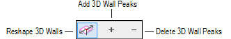
In any 3D view, when only a single wall is selected, the Reshape tool has three modes available.
Mode |
Description |
|---|---|
Reshape 3D Walls |
Adjusts the position of a selected wall vertex |
Add 3D Wall Peaks |
Adds a vertex to a wall for reshaping purposes |
Delete 3D Wall Peaks |
Deletes a wall vertex |
Walls can also be trimmed using the Trim tool; see “Trim Tool” on page 1058.
~~~~~~~~~~~~~~~~~~~~~~~~~

To change a wall’s length:
1. Select the wall to reshape.
2. Click the Selection tool from the Basic palette.
Single Object Interactive Scaling mode must be enabled.
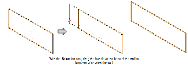
3. Position the cursor over an end selection handle, and click.
In a 3D view, the handles are at the base of the wall.
4. Move the mouse to lengthen or shorten the wall.
5. Click when the wall is at the desired length.
Wall length can also be changed with the Reshape tool in Top/Plan view. In a 3D view, draw a marquee with the Reshape tool to enclose the wall vertex in a marquee that is co-planar with the bottom wall elevation. Select the wall with the Reshape tool. The available modes switch to the 2D reshape modes, and 2D reshape functionality is enabled (see “2D Reshape Modes” on page 1042). This allows the wall length to be adjusted, even when in a 3D view.
~~~~~~~~~~~~~~~~~~~~~~~~~

To change the height of the wall:
1. In a 3D view, select the wall to reshape.
2. Click the Reshape tool from the Basic palette, and select Reshape 3D Walls mode.
3. Position the cursor over one of the handles in the middle of the top or bottom of the wall, and click.
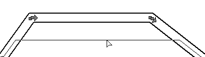
When the cursor is over a reshape handle, the standard arrow cursor changes into a double-headed, unfilled arrow.
4. Move the mouse to adjust the wall.
5. Click at the desired location.
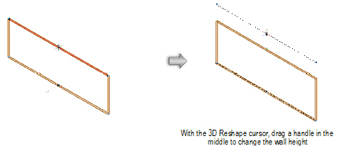
In the Object Info palette, the height change displays as a top or bottom offset value.
~~~~~~~~~~~~~~~~~~~~~~~~~

To change the height of a peak on the wall:
1. In a 3D view, select the wall to reshape.
2. Click the Reshape tool from the Basic palette, and select Reshape 3D Walls mode.
3. Position the cursor over one of the handles on the ends of the top or bottom of the wall, and click.
When the cursor is over a reshape handle, the standard arrow cursor changes into a double-headed, unfilled arrow.
4. Move the mouse to adjust the wall.
5. Click at the desired location.
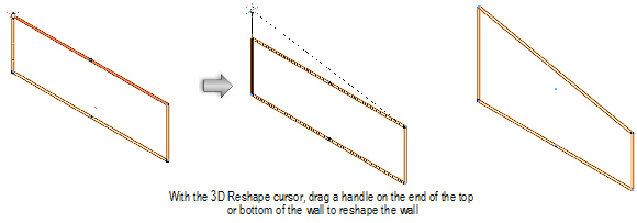
Changing the height of a wall peak does not change the height of the wall.
~~~~~~~~~~~~~~~~~~~~~~~~~

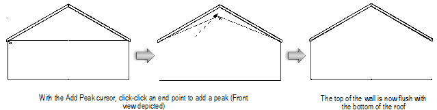
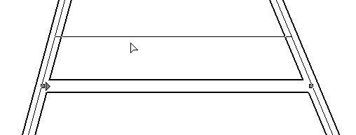
To add a vertex to a wall:
1. In a 3D view, select the wall that requires a peak (vertex).
2. Click the Reshape tool from the Basic palette, and select Add 3D Wall Peaks mode.
3. Position the cursor over an end point on one of the corners or an existing vertex, and click.
When the cursor is over an end point, the standard arrow cursor changes into a single-headed, filled arrow with shaded boxes on either side of the shaft.
4. Move the mouse to add a vertex to the top or bottom of the wall.
A vertex can be moved to any location along the same wall as long as the location does not pass another existing vertex.
5. Click when the vertex is at the desired location.
To reshape a curved wall to match a planar surface, use the Subtract Solids or Intersect Solids command with an object that matches the plane of the roof.
~~~~~~~~~~~~~~~~~~~~~~~~~

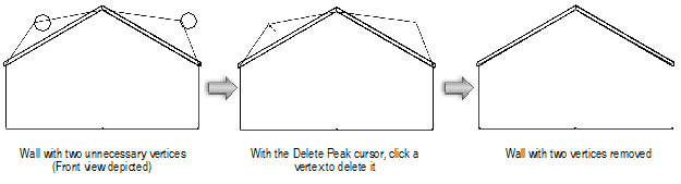
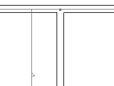
To delete a control point:
1. In a 3D view, select the wall with the peak (vertex) to be deleted.
2. Click the Reshape tool from the Basic palette, and select Delete 3D Wall Peaks mode.
3. Position the cursor over the vertex to delete.
When the cursor is over a vertex, the standard arrow cursor changes into a single-headed, filled arrow with a hollow diamond in the shaft.
4. Click on the vertex.
The vertex is removed and the wall is reshaped to the remaining vertices.
~~~~~~~~~~~~~~~~~~~~~~~~~

To change the radius of a round wall:
1. Select the round wall to edit.
2. Click the Selection tool from the Basic palette.
3. Position the cursor over the center control point, and click.
4. Move the mouse to change the radius, and click to set the end point.
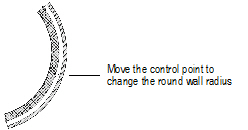
Flip the round wall arc by dragging toward, and through, the arc center.
~~~~~~~~~~~~~~~~~~~~~~~~~
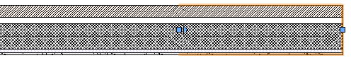
The Remove Wall Breaks tool cleans up any wall breaks or gaps that were created during editing. For example, when creating a new wall that joins an existing wall, if the new wall is later deleted, a break in the remaining wall displays at the joint. The Remove Wall Breaks tool can remove the break and any end caps.

To remove wall breaks:
1. Click the Remove Wall Breaks tool from the appropriate tool set.:
• Fundamentals: Walls tool set
• Design Series: Building Shell tool set
Alternatively, right-click (Windows) or Ctrl-click (Mac) on the wall and select Remove Break from the context menu.
2. Click and drag to create a marquee box around the wall break or end cap to remove.
The wall break or end cap is automatically removed.
![]()
~~~~~~~~~~~~~~~~~~~~~~~~~
 Moving
Connected Walls
Moving
Connected WallsThe Selection tool has an additional mode, Connected Walls, in the Vectorworks Architect and Landmark products. This mode automatically maintains the connection between the wall being moved and adjoining walls. The involved wall angles remain constrained throughout the move. While dragging a wall, you can enter precise offset distances in the Offset field of the Tool bar.
The Connected Walls mode does not apply to Y-joined walls or round walls.
Connections between T-joined walls and L-joined walls are also maintained if they are moved using the Move or Nudge command, or moved and/or duplicated using the Duplicate Array command or the Move by Points tool, as long as the ends of the moved or duplicated walls overlap with the walls to which they were originally connected.


To move a wall while maintaining its connection to adjacent walls:
1. Click the Selection tool from the Basic palette.
2. Select Connected Walls from the Tool bar.
3. Click on the desired wall and drag it to a new location; alternatively, change the wall length by editing the L value in the Object Info palette (polar coordinates), or by editing a dimension value. The walls stay connected during the move.
When you move a wall connected between two other walls, the wall being moved is resized to maintain the connection. A T- or L-joined wall, when moved beyond the end of the connected wall, disconnects the walls.
End-to-end walls joined as an L-join move together as a single wall.
For corner joined walls, all involved walls are resized to maintain the connection. A wall cannot be moved in such a way that its length equals zero.
To move a collection of walls without changing the walls relative to each other, deselect the Connected Walls mode, and then move the walls.
~~~~~~~~~~~~~~~~~~~~~~~~~
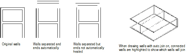
The Vectorworks preference Auto join walls automatically joins walls at corners and intersections, and automatically heals the mitered ends of walls when they are separated from one another. For T joins, the break in the side of the wall is healed. Walls can be in either 2D or 3D view.
When a core component has been set for walls with components, the components also automatically join. Core components, as well as the other components, join uncapped if they have the same fill, and capped otherwise.
To set the Auto join walls preference:
1. Select Tools > Options > Vectorworks Preferences.
2. On the Edit tab, select Auto join walls.
3. Click OK.
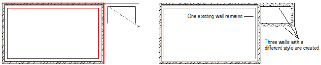
When the Vectorworks preference Auto join walls is on, walls drawn in Rectangle mode that are parallel and overlap or touch each other interact. The drawing operation can be performed using the default Add option, which combines interacting walls, or using the Subtract option, which deletes interacting wall segments. A set of rules determines these interactions.
The existing walls that interact with the new walls are highlighted while drawing.
The existing overlapped wall remains, and the new overlapping wall is not created.
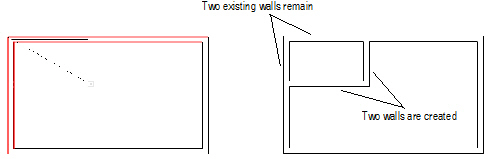
If the new wall extends the existing wall and has the same style, the existing wall is extended and the new wall is not created. If the new wall has a different style, it is created.
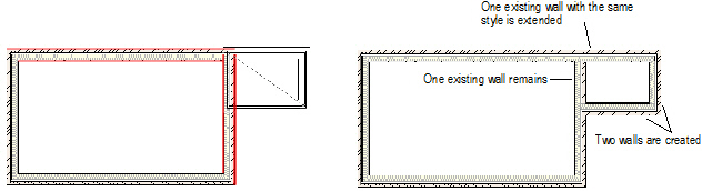
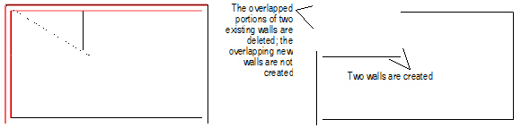
The overlapped portion of the existing wall is deleted, and the new overlapping wall is not created.
If the new wall extends the existing wall and has the same style, the existing wall is extended and the new wall is not created.
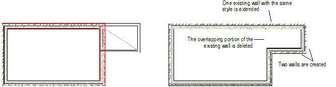
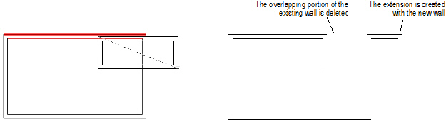
If the new wall partially extends and partially overlaps an existing wall, the overlapping portion is deleted and the extending portion is created with the new wall.
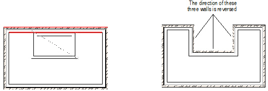
When a wall subtraction requires that the existing walls change direction to maintain the correct orientation, the wall direction changes automatically (see “Wall Direction” on page 502).
~~~~~~~~~~~~~~~~~~~~~~~~~
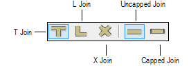
The Wall Join tool joins straight or curved wall segments not already connected using the Auto join walls preference. (See “Automatically Joining Walls” on page 538 for information on Auto join walls.) There are three modes for joining walls and two end cap modes.
Mode |
Description |
|---|---|
T Join |
Lengthens or shortens one wall segment until it intersects with the second wall segment selected; creates Y joins by joining the first selected wall to two sections of an existing L join |
L Join |
Joins the closest ends of two walls to create a corner |
X Join |
Joins two wall segments at the point where they intersect |
Uncapped Join |
Applies an uncapped join to wall join operations |
Capped Join |
Applies a capped join to wall join operations |
To temporarily activate this tool, right-click (Windows) or Ctrl-click (Mac) on a wall, and select Join from the context menu. The tool defaults to the mode used previously with the tool.
Click here for a video tip about this topic (Internet access required).
~~~~~~~~~~~~~~~~~~~~~~~~~
T Join mode lengthens or shortens the first wall segment selected until it intersects with the second wall segment selected. As only the first wall is altered, this mode does not create corner joins.

To join walls with the T Join mode:
1. Click the Wall Join tool from the appropriate tool set:
• Fundamentals: Walls tool set
• Design Series: Building Shell tool set
Alternatively, right-click (Windows) or Ctrl-click (Mac) on the first wall to join and select Join from the context menu.
2. Click T Join from the Tool bar.
3. Select the wall segment that must change length to intersect with the other wall.
4. Select the second wall segment to join.
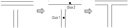
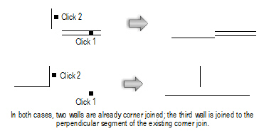
To create a T join to an existing corner, join the wall segment to the perpendicular corner segment. This creates a clean join between the walls.
~~~~~~~~~~~~~~~~~~~~~~~~~
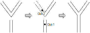
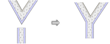
Y wall joins are not automatically created when you use the Auto join walls preference. (See “Edit Preferences” on page 47 for information on Auto join walls.) Instead, use the T Join mode to create Y wall joins.

To create a Y wall join of three wall segments:
1. Click the Wall Join tool from the appropriate tool set:
• Fundamentals: Walls tool set
• Design Series: Building Shell tool set
Alternatively, right-click (Windows) or Ctrl-click (Mac) on the first wall to join and select Join from the context menu.
2. Click T Join from the Tool bar.
3. Select the wall segment that must change length to abut the two previously joined wall segments.
4. Select one of the two wall segments to join.
The wall segments are joined.
~~~~~~~~~~~~~~~~~~~~~~~~~
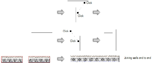
L Join mode joins the closest ends of two walls to create a corner, or joins two walls end to end. Both wall lengths are automatically resized as necessary to meet cleanly.

To join walls with the L Join mode:
1. Click the Wall Join tool from the appropriate tool set:
• Fundamentals: Walls tool set
• Design Series: Building Shell tool set
Alternatively, right-click (Windows) or Ctrl-click (Mac) on the wall and select Join from the context menu.
2. Click L Join from the Tool bar.
3. Select the first wall segment to join.
4. Select the second wall segment to join. For corner joins, the location of the clicks defines the direction of the L.
The wall lengths are automatically resized and joined.
~~~~~~~~~~~~~~~~~~~~~~~~~
X Join mode joins two wall segments at the point where they intersect. Because neither wall segment’s length is altered, the two segments must already intersect in order to use this mode.

To join walls with the X Join mode:
1. Click the Wall Join tool from the appropriate tool set:
• Fundamentals: Walls tool set
• Design Series: Building Shell tool set
Alternatively, right-click (Windows) or Ctrl-click (Mac) on the wall and select Join from the context menu.
2. Click X Join from the Tool bar.
3. Select the wall segment to become non-load bearing.
4. Select the wall segment to become load bearing.
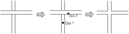
The first wall segment selected is split into two walls segments, which are joined to the load bearing wall.
~~~~~~~~~~~~~~~~~~~~~~~~~
The Fillet tool, located on the Basic palette, joins two wall segments by creating a round wall between them. See “Creating Fillets and Chamfers” on page 1075.
~~~~~~~~~~~~~~~~~~~~~~~~~
 Joining
Wall Components
Joining
Wall ComponentsThe Component Join tool joins the selected components between two straight wall segments; components within pre-existing joined wall segments can also be joined. There are three modes for joining wall components.

Mode |
Description |
|---|---|
T Join |
Extends or shortens one wall component segment until it intersects with a second wall component segment |
L Join |
Joins the closest ends of two wall components to create a corner |
Capped Join |
Applies a capped join to the component being joined |
Components can be joined to the edge of walls instead of specific components in Capped Join mode.
Normally, when you join walls with the Wall Join tool, and the Auto join walls preference is enabled, the components automatically join correctly. A core component must be set. (See “Joining Walls” on page 541.)
The Component Join tool is useful for adjusting components that did not join as desired when walls were connected, even in complex wall joins.
Click here for a video tip about this topic (Internet access required).
~~~~~~~~~~~~~~~~~~~~~~~~~
 T
Join Mode
T
Join ModeThe T Join mode extends or shortens one wall component segment until it intersects with a second wall component segment. As only the first component is extended, this mode will not create corner type joins. (For those, use the L join mode.)

To join wall components with the T Join mode:
1. Click the Component Join tool from the Building Shell tool set.
2. Click T Join from the Tool bar.
3. Select the component within the wall segment to join. The component is highlighted.
4. Select the second wall segment to join. The component to be joined is highlighted.
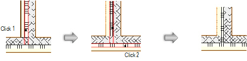
5. Repeat steps 3 and 4 for each component within the wall segment that needs to be joined.
~~~~~~~~~~~~~~~~~~~~~~~~~
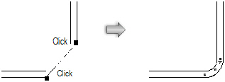
 L
Join Mode
L
Join ModeThe L Join mode joins the closest ends of two wall components to create a corner. Both component lengths are extended or shortened, as necessary, until they meet cleanly.

To join wall components with the L Join mode:
1. Click the Component Join tool from the Building Shell tool set.
2. Click L Join from the Tool bar.
3. Select the component within the wall segment to join.
4. Select the second wall segment to join. The component to be joined is highlighted.
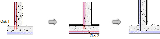
5. Repeat steps 3 and 4 for each component within the wall segment that needs to be joined.
~~~~~~~~~~~~~~~~~~~~~~~~~
 Capped
Join Mode
Capped
Join ModeLike the T Join mode, the Capped Join mode extends or shortens one wall component until it intersects with a second component. The component end is capped at the point where it joins the other wall.

To join wall components with the Capped Join mode:
1. Click the Component Join tool from the Building Shell tool set.
2. Click Capped Join from the Tool bar.
3. Select the component within the wall segment to join.
4. Select the second wall segment to join. The component to be joined is highlighted.
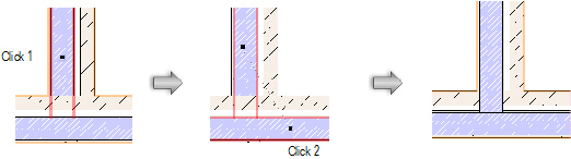
5. Repeat steps 3 and 4 for each component within the wall segment that needs to be joined.
~~~~~~~~~~~~~~~~~~~~~~~~~
 Editing Curtain
Walls
Editing Curtain
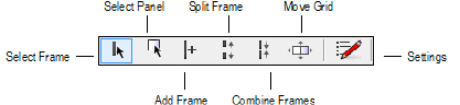
WallsThe Edit Curtain Wall tool manipulates the frames and panels of curtain walls. Once a curtain wall is selected with the tool, the modes allow you to select frames and panels; delete frames and panels; add, split, and combine frames; move frame and panel sets along a wall; and edit frame and panel settings.
When a curtain wall is selected with the Selection tool, two context menu commands become available. The Edit Using Reshape Tool command activates the Reshape tool to reshape the walls as described in “Reshaping Walls” on page 532. The Edit Using Edit Curtain Wall Tool command activates the Edit Curtain Wall tool.
Mode |
Description |
|---|---|
Select Frame |
Selects one or more frames |
Select Panel |
Selects one or more panels |
Add Frame |
Inserts new frames into the curtain wall |
Split Frame |
Splits a frame into multiple pieces, so that one portion of the frame can be independently moved, edited, or deleted |
Combine Frames |
Combines two collinear frames into a single frame |
Move Grid |
Moves an entire set of frames and panels relative to the curtain wall |
Settings |
Selected frame or panel parameters can be edited |
~~~~~~~~~~~~~~~~~~~~~~~~~

To select and manipulate curtain wall frames:
1. Click the Edit Curtain Wall tool from the Building Shell tool set, and click Select Frame mode from the Tool bar.
2. Select the curtain wall to edit.
3. Select the frame or frames to edit, move, or delete.
The Edit Curtain Wall tool works similarly to the Selection tool. Frames can be selected for editing in a variety of ways.When a single frame is selected, end handles allow the frame to be reshaped.
Method |
Selection Action |
|---|---|
Click |
Standard selection method; selects a single object only |
Shift-click |
Selects multiple objects as each object is clicked; also can be used to deselect one or more objects without affecting other selected objects |
Option-drag (Mac) or Ctrl-drag (Windows) |
Places a copy of the object where the mouse button is released |
Rectangle marquee |
Selects all objects that are completely contained within the marquee |
Shift-marquee |
Reverses the selection status of objects inside a marquee; if objects inside the marquee are selected, this method deselects those objects |
Option-marquee (Mac) or Alt-marquee (Windows) |
Selects all objects that the marquee passes through, as well as those contained within the marquee |
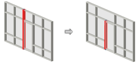
4. A single, selected frame can be reshaped, moved by dragging, copied, or deleted. The frame must be connected on both ends to another frame. If deleting or moving a frame causes any frames to become disconnected, they are automatically extended until they join a frame.
Selected frames can be deleted by pressing delete, or alternatively, right-click (Windows) or Ctrl-click (Mac) on the frame and select Delete Frames from the context menu.
Selected frames can be evenly distributed relative to the wall. Frames must be horizontal or vertical, and at least three frames must be selected. Right-click (Windows) or Ctrl-click (Mac) on the frames and select Distribute Frames from the context menu. The frames on the ends of the selection do not move.
Panels automatically adjust to conform to the new frame positions.
5. The settings of selected frames can be edited by clicking the Settings mode from the Tool bar.
Alternatively, right-click (Windows) or Ctrl-click (Mac) on the frame and select Settings from the context menu.
~~~~~~~~~~~~~~~~~~~~~~~~~

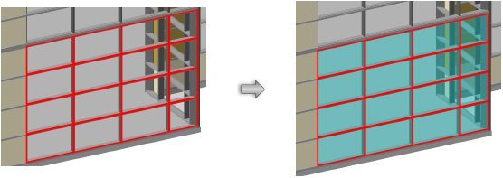
To select and manipulate curtain wall panels:
1. Click the Edit Curtain Wall tool from the Building Shell tool set, and click Select Panel mode from the Tool bar.
2. Select the curtain wall to edit.
3. Select the panel or panels to edit. Panels cannot be moved; the position of the panels is determined by the frames. Selecting panels is very similar to selecting frames; see “Editing Curtain Wall Frames” on page 548.
4. The settings of selected panels can be edited by clicking the Settings mode from the Tool bar.
Alternatively, right-click (Windows) or Ctrl-click (Mac) on the frame and select Settings from the context menu.
When one or more curtain wall panels are selected, a door or window can be easily inserted. Right-click (Windows) or Ctrl-click (Mac) on the panel and select Insert Window or Insert Door from the context menu. The window or door is automatically inserted as a curtain wall window or door, and sized to fit within the selected panel or panels.
~~~~~~~~~~~~~~~~~~~~~~~~~

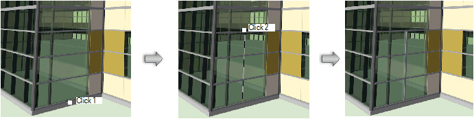
To add new curtain wall frames:
1. Click the Edit Curtain Wall tool from the Building Shell tool set, and click Add Frame mode from the Tool bar.
2. Select the curtain wall to edit.
3. Click at the start point of the new frame, and then click on the end point of the new frame. The start and end points must be placed on existing frames.
Press the Shift key to constrain the placement of the second point of the frame horizontally or vertically.
4. The frame is added, acquiring its attributes from the curtain wall grid settings.
~~~~~~~~~~~~~~~~~~~~~~~~~

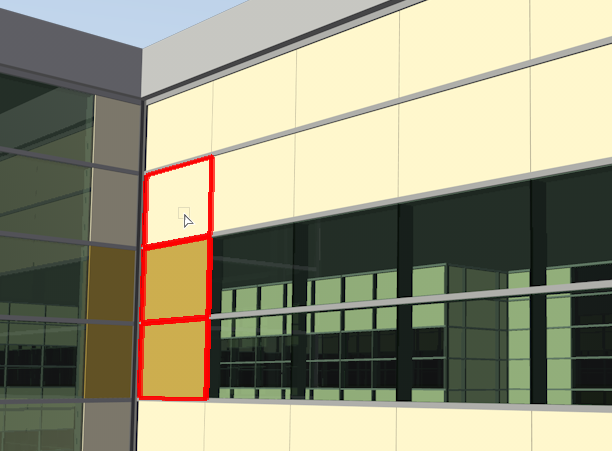
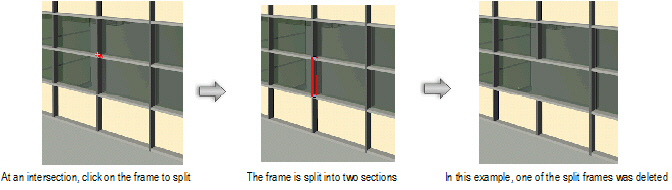
To split curtain wall frames:
1. Click the Edit Curtain Wall tool from the Building Shell tool set, and click Split Frame mode from the Tool bar.
2. Select the curtain wall to edit.
3. Click on a frame to split it into sections.
A frame can only be split at a frame intersection. A red split cursor displays to indicate locations where the frame can be split.
4. The frame is split, and the resulting sections can be dragged, deleted, or have their settings changed independently.
~~~~~~~~~~~~~~~~~~~~~~~~~

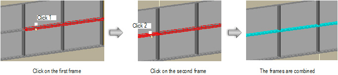
To combine two collinear curtain wall frames:
1. Click the Edit Curtain Wall tool from the Building Shell tool set, and click Combine Frame mode from the Tool bar.
2. Select the curtain wall to edit.
3. Click each of the two frames to be combined. Frames must be collinear.
At a four-way frame intersection, it may be necessary to split a perpendicular frame to be able to join collinear frames.
4. One frame is created. The attributes of the first clicked frame apply to both frames once they are combined.
~~~~~~~~~~~~~~~~~~~~~~~~~
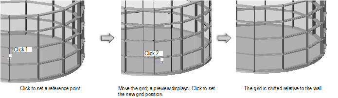
The frames and panels of a curtain wall form a grid or pattern relative to the wall. Moving the grid along the wall can be useful to center a grid pattern on a wall.

To move the curtain wall grid relative to the wall:
1. Click the Edit Curtain Wall tool from the Building Shell tool set, and click Move Grid mode from the Tool bar.
2. Select the curtain wall to edit.
3. Click to set a reference point for the grid.
4. Move the cursor to shift the entire grid of frames and panels, along with any doors and windows, relative to the wall.
The frames and panels shift to the left or right along the wall. A preview of the grid displays.
5. Click to set the new location of the curtain wall grid.
~~~~~~~~~~~~~~~~~~~~~~~~~
The Settings mode changes the settings of either frames or panels that have been selected with the Select Frame or Select Panel mode of the Edit Curtain Wall tool.

To change curtain wall frame or panel settings:
1. Click the Edit Curtain Wall tool from the Building Shell tool set.
2. Select the curtain wall to edit.
3. Using either Select Frame mode or Select Panel mode of the Edit Curtain Wall tool, select the frames or panels to edit.
4. Click Settings mode from the Tool bar.
Alternatively, right-click (Windows) or Ctrl-click (Mac) on the frame or panel and select Edit Frames or Edit Panels from the context menu.
5. The Frame Settings or Panel Settings dialog box opens. Change the frame or panel settings as described in “Setting Curtain Wall Frame Parameters” on page 521 or “Setting Curtain Wall Panel Parameters” on page 523.
The Frame Settings dialog box, when opened in this way, does not include the frame category selection on the left, since the frames to edit have already been selected.
6. Click OK.
The frame or panel settings are changed.
~~~~~~~~~~~~~~~~~~~~~~~~~
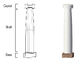
The Vectorworks Fundamentals product and all Vectorworks Design Series products include a basic architectural column object (for aesthetic and space-defining purposes). In the Architect product, the column object offers additional structural capabilities, and a pilaster object is provided.
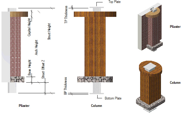
In the Architect product, columns and pilasters can be architectural in nature, structural in nature, or both. Use the Column tool or Pilaster tool to draw an object that not only reflects the architectural appearance of a column/pilaster, but also defines it in structural terms that can be used in an engineering analysis of the building. Structural and architectural elements can be displayed or hidden, as desired. The column ID can also, optionally, be placed on the drawing. Additionally, in the Architect product, the column/pilaster can be exported to IFC format for exchange with structural analysis programs.
A pilaster can be placed in a wall (however, a column cannot be placed in a wall). A pilaster inserted in a wall can set its architectural height relative to the wall.
Tool access varies depending on the Vectorworks product installed:
Vectorworks Product |
Tool Set / Tool |
|---|---|
Fundamentals |
Walls > Column (basic column) |
Architect and Designer |
Building Shell > Column (architectural column with additional capabilities) |
Architect and Designer |
Building Shell > Pilaster |
Landmark and Spotlight |
Building Shell > Column (basic column) |

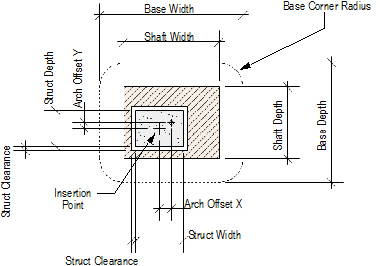
To create a column:

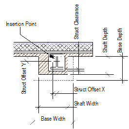
To create a pilaster:
1. Click the Column tool or the Pilaster tool from the appropriate tool set:
• Fundamentals: Walls tool set
• Design Series: Building Shell tool set
2. Click to place the object in the drawing, and click again to set the object’s rotation. If this is the first time a column/pilaster is placed in the drawing, the object properties dialog box opens. These parameters apply to subsequently created columns/pilasters; they can be changed later by accessing them from the Object Info palette.
3. Specify the column/pilaster properties and click OK.
To create a circular or square shaft, capital, or base, enter the same value for the width and depth.
The basic column object is available with the Vectorworks Fundamentals, Landmark and Spotlight products.
Click to show/hide the parameters.
 Architect Column and Pilaster
Parameters
Architect Column and Pilaster
Parameters The architect column and pilaster objects are available with the Vectorworks Architect and Designer products.
Click to show/hide the parameters.
~~~~~~~~~~~~~~~~~~~~~~~~~
 Exporting
Columns and Pilasters to IFC Format
Exporting
Columns and Pilasters to IFC FormatIn the Vectorworks Architect product, columns and pilasters can be exported to IFC format for exchange with structural analysis programs. If the column/pilaster has both architectural and structural components enabled, the object is exported as an IfcColumn and the architectural component is exported as an IfcCovering with an IfcCoveringType of Cladding. If the column/pilaster has only an architectural or structural component enabled, the object is exported as an IfcColumn.
~~~~~~~~~~~~~~~~~~~~~~~~~
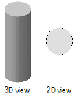
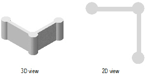
The Pillar command converts any closed 2D shape—rectangle, circle, oval, or polygon—into a pillar. In addition, use it on open 2D shapes, such as lines and polylines, to create a flat, screen-like object. These objects include such things as movie screens, room dividers, and moving walls. Once created, a pillar can be joined to a wall.
To create a pillar:
1. Click on the object to convert.
2. Select the Pillar command from the appropriate menu:
• Fundamentals: Model > AEC > Pillar
• Architect: AEC > Pillar
• Landmark: Landmark > Architectural > Pillar
• Spotlight: Spotlight > Architectural > Pillar
The Pillar Preferences dialog box opens.
3. Enter a pillar height.
4. Click OK.
After creation, the pillar can be edited by selecting Modify > Edit Pillar. See “Object Editing Mode” on page 1002.
~~~~~~~~~~~~~~~~~~~~~~~~~
Walls and pillars can be joined together. Any number of walls can connect to the pillar as long as space exists on the pillar.
The pillar needs to be joined to the end of a wall; it cannot be added to an existing wall intersection such as the corner of L-joined or T-joined walls.
To join a pillar to a wall:
1. Click on the pillar.
2. Draw the walls.
If the Auto-join feature is enabled, then the walls automatically connect to the pillar.
If the Auto-join feature is disabled, then click the Wall Join tool from the Walls tool set or the Building Shell tool set and join the walls to the pillar.
~~~~~~~~~~~~~~~~~~~~~~~~~