 IFC
OverviewIFC
Overview
IFC
OverviewIFC
OverviewThe Vectorworks Architect and Landmark products support Building Information Model (BIM) interoperability using the Industry Foundation Classes (IFC) data specification and file formats. Vectorworks currently supports versions 2x2 and 2x3 and is certified by buildingSMART International for the export of models based on the IFC2x3 Coordination View 2.0 – Architecture model view definition, as well as import of any IFC2x3 Coordination View 2.0 model.
IFC is an open standard, developed and maintained by buildingSMART International, for building data that permits information to be shared and maintained throughout the life cycle of the construction project: design, analysis, specification, fabrication, construction, and occupancy.
The capabilities and usage for IFC data standards are still evolving. However, objects and models containing IFC data have been proven to be a useful part of the design process. Some examples of the use of IFC data include:
• Collaborative design, where an architect exports an architectural model to a structural engineer for analysis and design, and then imports the structural model, in an IFC format, for coordination purposes
• Energy performance simulation and analysis of a building envelope and systems
• Automated analysis of code compliance
• Space planning and space inventory analysis
Central to the concept of IFC is the idea of “semantic objects.” Like Vectorworks plug-in objects, IFC objects are more than just collections of geometry; they have a meaning within the building fabric itself, be it as a door, a wall, a window, or a handrail. The following Vectorworks plug-in objects have default IFC2x3 object types and properties assigned, but they may be edited by the user as necessary. These Vectorworks plug-in objects are automatically converted upon export to the corresponding IFC object types shown. Additionally, most content in the Vectorworks Architect, Landmark, and Designer symbol libraries has default IFC2x3 object types and properties assigned, but symbols may be edited by the user, as necessary, and are automatically converted upon export.
Base Cabinet [IfcFurnishingElement] |
Bath-Shower [IfcFlowTerminal] |
Ceiling Grid [IfcCovering] |
Clothes Rod [IfcFurnishingElement] |
Column [IfcColumn] |
Comm Device [IfcDistributionFlowElement] |
Compartment Sink [IfcFlowTerminal] |
Counter Top [IfcFurnishingElement] |
Curtain Wall (Straight & Curved) [IfcCurtainWall] |
Curtain Wall Frames [ifcMember] |
Curtain Wall Panels [IfcPlate] |
Desk [IfcFurnishingElement] |
Door [IfcDoor] |
Drilled Footing [IfcFooting] |
Simple Elevator [IfcTransportElement] |
Escalator [IfcTransportElement] |
Fireplace [IfcDistributionFlowElement] |
Floor [IfcSlab] |
Framing Member [IfcMember or IfcBeam] |
Grab Bars [IfcRailing] |
Guardrail (Curved & Straight) [IfcRailing] |
Handrail (Curved & Straight) [IfcRailing] |
HVAC Damper [IfcDistributionFlowElement] |
HVAC Diffuser [IfcDistributionFlowElement] |
HVAC Elbow Duct [IfcDistributionFlowElement] |
HVAC Flex Duct [IfcDistributionFlowElement] |
HVAC Outlet [IfcDistributionFlowElement] |
HVAC Splitter [IfcDistributionFlowElement] |
HVAC Straight Duct [IfcDistributionFlowElement] |
HVAC Transition [IfcDistributionFlowElement] |
HVAC Vertical Duct [IfcDistributionFlowElement] |
HVAC Vertical Elbow [IfcDistributionFlowElement] |
Incandescent Fixture [IfcDistributionFlowElement] |
Landscape Wall (including Arc and Bezier) [IfcWall] |
Massing Model (on layer mapped to site) [IfcBuilding] |
Mullion [IfcMember] |
Parking Spaces [IfcSpace] |
Pilaster [IfcColumn] |
Pillar [IfcColumn] |
Piping Run [IfcDistributionFlowElement] |
Plant [IfcBuildingElementProxy] |
Ramp [IfcRamp] |
Receptacle [IfcDistributionFlowElement] |
Roadway (all types) [IfcTransportElement] |
Roof [IfcRoof containing instances of IfcSlab] |
Roof Face [IfcSlab] |
Seating Layout [IfcFurnishingElement] |
Round Wall [IfcWall or IfcWallStandardCase] |
Wall [IfcWall or IfcWallStandardCase] |
Site Model [IfcSite] |
Shelving Unit [IfcFurnishingElement] |
Slab [IfcSlab] |
Space [IfcSpace] |
Stair (including Simple and Custom) [IfcStair] |
Switch [IfcDistributionFlowElement] |
Table [IfcFurnishingElement] |
Tables and Chairs [IfcFurnishingElement] |
Toilet Fixture [IfcFlowTerminal] |
Utility Cabinet [IfcFurnishing Element] |
Wall Cabinet [IfcFurnishingElement] |
Window [IfcWindow] |
Workstation Counter [IfcFurnishingElement] |
Workstation Overhead [IfcFurnishingElement] |
Workstation Panel [IfcFurnishingElement] |
Workstation Pedestal [IfcFurnishingElement] |
|
With the IFC Data command, users can assign object types and properties to arbitrary collections of geometry so that other applications that use these IFC files can identify these objects.
When an IFC file is imported into a Vectorworks file, IfcSpace objects are translated into the corresponding Vectorworks Space object. Since the properties of other objects cannot easily be matched to all the corresponding Vectorworks object properties and controlling parameters, the objects are imported into the Vectorworks file as a particular and flexible kind of plug-in object: an “IFC Entity.” The semantic definition of the IFC Entity - IfcColumn, IfcWall, IfcWindow, for example - is maintained and displayed. Like a group or symbol, an IFC Entity can contain an arbitrary collection of geometry, usually generic or constructive solid (CSG), but like a plug-in object, it can be inserted into walls and has sets of data and properties attached. With this generalized import capability, the Vectorworks program can import any kind of object supported by the IFC data standard, regardless of whether it has a corresponding parametric plug-in object.
Click here for a video tip about this topic (Internet access required).
~~~~~~~~~~~~~~~~~~~~~~~~~
 IFC
Workflows
IFC
WorkflowsGenerally, the Vectorworks program expects users to export their files as entire projects (sites with buildings consisting of stories), to be exchanged or analyzed with other IFC-compatible applications. When you use the Export IFC Project command, you assign design layers to building stories for meaningful export (Vectorworks Architect required). For a project initially set up with stories, mapping is done automatically so that the layers assigned to the building stories are automatically included in the Mapped Layers list and are mapped to an appropriately named IFC Story (Vectorworks Architect required). Mapping can also be controlled manually, allowing you to override or edit the automated process or make any subsequent changes. The Import IFC command automatically assigns IFC building stories to their own design layers.
To make Vectorworks building models easy to export to IFC, the following guidelines may be useful:
• Set up the project initially with stories as described in “Setting Up the Building Structure with Stories” on page 168 (Vectorworks Architect required).
• Design layers for the building model should correspond to building stories (Vectorworks Architect required), not categories of information. (Use classes for categorization.)
• Take care to set up the elevation values of layers correctly, and verify that all the objects in the drawing are aligned correctly vertically. Examining the project in Unified View mode makes this much easier.
• Use standard Vectorworks plug-in objects listed in “IFC Format Interoperability” on page 1737 wherever possible.
• Use the IFC Data command to attach IFC data to custom user-defined hybrid or 3D symbols, custom 3D elements, or auto-hybrid objects, so that they will be recognized at IFC export.
• Use the VA Create Schedule command (Vectorworks Architect required) to generate default IFC schedules, or create your own schedules to verify and correct the IFC data attached to objects. See “Records and Schedules” on page 1853.
• Test the quality of the IFC export file by verifying it in an IFC model browsing utility. Almost all IFC browsers can traverse the IFC hierarchical “tree” structure to view and validate the model. Some examples of IFC browsers available at this time include:
• Solibri Model Viewer (Macintosh or Windows)
• Constructivity Model Viewer (Windows)
• RDF IFC Viewer (Windows; Macintosh and Linux versions planned)
• Field 3D (iOS)
• IFC WebServer (web browser)
• xBIM Xplorer (Windows)
• IfcPlusPlus (Windows)
For more information about additional available IFC viewers and other IFC-compatible applications, visit the buildingSMART IFC-Compatible Implementations Database website or IfcWiki.org.
~~~~~~~~~~~~~~~~~~~~~~~~~
 Assigning
IFC Data to Objects
Assigning
IFC Data to ObjectsWhen a building project is exported to an IFC file, Vectorworks plug-in objects and pre-assigned symbols are automatically assigned to IFC entities. Simple hybrid or 3D geometric objects, unless they receive IFC assignments, are not exported. To be exported, these object associations must be made prior to export with the IFC Data command. Assigning IFC data to an object does not alter it in any visible way. The object can still be edited with standard Vectorworks tools and commands. An example of this would be to use a floor or slab object to model a flat ceiling (Vectorworks Architect required). Select the floor or slab in the model, and then select the IFC Data command. From the list in the Select IFC Entity dialog box, select IfcCovering, the correct assignment for a ceiling. Then, in the IFC Data dialog box, select CEILING from the PredefinedType list in the Properties for the selected Data Set lists.
The IFC Zones command attaches IFC data to space zones. See “Assigning IFC Data to Space Zones” on page 1742.
An object can also be “wrapped” in a container so that it is identified in the Vectorworks file as an IFC Entity object. Editing an IFC Entity is less direct than editing simple Vectorworks objects with IFC data attached. For this reason, an IFC Entity can be useful for model elements that need to be secured from casual changes.
To assign IFC data:
1. Select the object, group, symbol instance, or symbol definition for assignment of IFC data. More than one item can be selected at one time.
IFC data applied to symbol instances affect only the selected instances, not all instances. To attach IFC data to symbol definitions, select the symbol definition in the Resource Browser. Right-click (Windows) or Ctrl-click (Macintosh) on the symbol and select IFC Data from the context menu. This attaches the IFC data to future symbol placements, and to any current instances that do not have IFC data already attached to them.
2. Select the IFC Data command from the appropriate menu:
• Architect: AEC > IFC Data
• Landmark: Landmark > Architectural > IFC Data
Alternatively, select Show IFC Data from the Coordinate/IFC menu on the Object Info palette to enable IFC-related information display on the palette, and then click IFC Data from the Object Info palette.

The Select IFC Entity dialog box opens, listing available IFC object types.
Click to show/hide the parameters.
3. Select the object type and click OK.
The IFC Data dialog box opens.
Click to show/hide the parameters.
4. Click OK to assign the IFC data to the object, or create the IFC entity. The Object Info palette displays the selected IFC object or entity information (IFC value type and the object name, if any) when Show IFC Data is enabled on the palette. Objects like walls and slabs, with default IFC data assigned, display with <Default> to indicate that the default IFC data have not been modified.
The geometry of IFC entities can be edited with the Modify > Edit IFC Entity command; alternatively, right-click (Windows) or Ctrl-click (Macintosh) on the IFC entity and select Edit from the context menu.
~~~~~~~~~~~~~~~~~~~~~~~~~
 Assigning IFC Data to Space Zones
The IFC Zones command attaches IFC data to the specified IFC zones from the current file.
Zones are assigned to space objects from the Occupancy pane of the Space Settings dialog box (see “Space Settings: Occupancy Pane” on page 404).
To attach IFC data to zones in use in the file:
1. Select the IFC Zones command from the appropriate menu:
• Architect: AEC > IFC Zones
• Landmark: Landmark > Architectural > IFC Zones
The IFC Zones dialog box opens. Zones in use in the file are listed above the divider line; available IFC zones are listed below the divider.
2. Select a zone and click OK. Only one zone can be selected at a time.
3. The IFC Data dialog box opens. The object type is automatically set to ifcZone, and the property Name value set to the zone name. See “Assigning IFC Data to Objects” on page 1740.
4. Click OK to attach the IFC data to the zone.
At IFC export, the IFC zone data is automatically applied to all space objects with a matching zone definition.
~~~~~~~~~~~~~~~~~~~~~~~~~
 Viewing
and Editing IFC Data
Viewing
and Editing IFC DataThe data attached to custom Vectorworks objects or IFC entities, whether created in the Vectorworks program or imported from an IFC file, can be viewed and edited with the IFC Data command or from the Object Info palette. In addition, the IFC object that corresponds to a Vectorworks plug-in object, such as a Space object, window, or wall, can be viewed.
To access IFC data:
1. Select the IFC entity or Vectorworks plug-in object. Multiple items can be selected.
2. Select AEC > IFC Data (Vectorworks Architect workspace) or Landmark >Architectural > IFC Data (Landmark workspace).
Alternatively, click IFC Data from the Object Info palette (Show IFC Data must be enabled from the Coordinate/IFC menu on the Object Info palette to enable IFC-related information display on the palette).
When multiple items have been selected, edits apply to all eligible objects in the selection.
If you have selected a group that contains objects with multiple IfcObjectTypes, the Choose IFC Type dialog box opens. Select the IFC Type to apply to the group. Optionally remove the IFC data from the contained objects.
3. When the items to be edited have been specified if necessary, the IFC Data dialog box opens. View or edit the IFC data as described in “Assigning IFC Data to Objects” on page 1740 and click OK.
If an IFC entity was selected, the IFC Data dialog box displays the data attached to the entity as described in “Assigning IFC Data to Objects” on page 1740; the data can be edited. If a Vectorworks plug-in object was selected, the IFC Data dialog box displays the corresponding IFC Object type. At export, the object will be converted to that type of entity.
~~~~~~~~~~~~~~~~~~~~~~~~~
 Using
Custom IFC Property Sets
Using
Custom IFC Property SetsProperty sets (Pset_XxxxXxxx) are used to assign groups of individual data fields, or properties, to IFC entities. Property sets can be very specific to an IFC entity, such as Pset_WallCommon to IfcWall, or more generally applied to any IFC entity, such as Pset_ManufacturerTypeInformation. Some property sets and their values are explicitly predefined and listed in the IFC specification; the naming convention Pset_Xxx applies to these officially specified property sets.
Due to the extensible nature of IFC, any user-defined data, even when not explicitly identified in the IFC specification, can still be captured and exchanged using custom property sets. Custom property sets must follow technical encoding conventions. They must have unique and allowable names; the names cannot duplicate specified property set names or begin with “Pset_.”
Record formats allow custom property sets to be saved and exchanged. See “Record Formats” on page 258 for more information on record formats.
To use a custom property set, first create the record format to define the data to be captured and exchanged in IFC format. The record format name defines the name of the custom property set. Record formats designated for IFC export should be named with a VwPset_ or ePset_ prefix, or use a name that is defined by a specific Model View Definition (MVD) or documented model Exchange Requirement (ER). Record format names are case sensitive, and should not contain blank spaces (use an underscore if needed). In the following example, the record format is named “ePset_MyDataExchange.”
The record format can consist of any number of fields, designated by a Field Name and a Field Type; see “Creating Record Formats” on page 258. To be compatible with IFC standards, each field name must be paired with a second field name that identifies an IFC value (IfcValue) type. Each pair must have the same field type.
For example, the Field Name “Reference,” with a Text Type, is followed by the Field Name “IfcIdentifier,” also with a Text Type. The “IfcIdentifier” field indicates the kind of value type being used; in this case, it is a simple text ID string (IfcSimpleValue:IfcIdentifier).
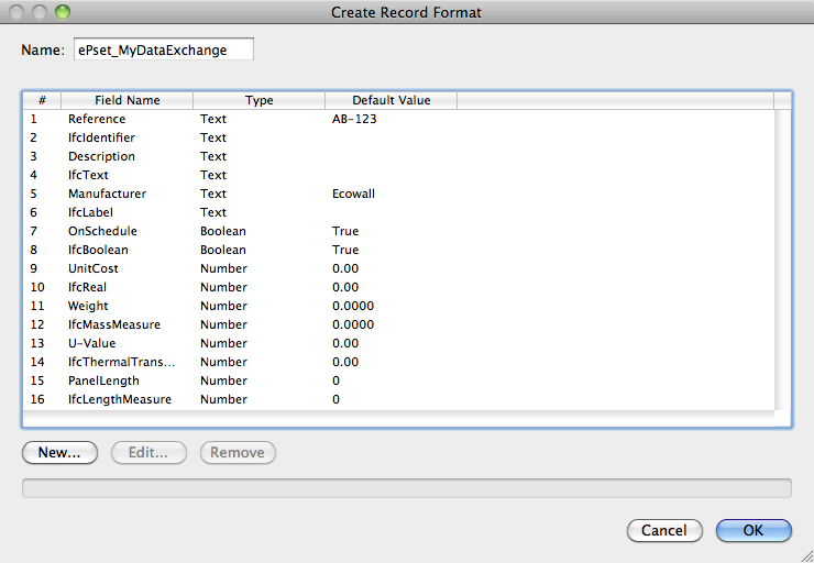
When creating record format fields, a default value can be specified. The default values are optional, except for number fields, which require at least a zero value to be entered. However, the default values for the IFC field names are ignored when converted to custom property sets.
Deciding which IFC value type and record format field type to use depends on the kind of information being captured by the field, such as a simple number, a TRUE/FALSE choice, a text string or simple label, or a measurement. In the Vectorworks program, allowable types include Integer, Boolean, Text, or Number. The Field Name identifying an IFC value type should be based on the IFC specification for the different defined types of values (IfcValue), as shown in the following list.
IFC Value Types |
Vectorworks Record Format Field Type and Description |
|---|---|
IfcSimpleValue |
These are the most common and cover most user cases |
IfcInteger |
Integer: a simple whole number ranging from -32,7568 to 32,767 |
IfcReal |
Number: General or Decimal |
IfcBoolean |
Boolean: also known as TRUE or FALSE |
IfcLogical |
Boolean: similar to Boolean, but can include a value of “UNKNOWN” |
IfcIdentifier |
Text: a simple text ID string, usually a mix of alphanumeric characters and symbols |
IfcLabel |
Text: a simple text name string, usually a mix of alphanumeric characters |
IfcText |
Text: a descriptive text field string of up to 255 characters |
IfcMeasureValue |
A complete list can be found in the IFC2x3 TC1 specification |
IfcAreaMeasure |
Number: Dimension Area |
IfcLengthMeasure |
Number: Dimension |
IfcMassMeasure |
Number: General or Decimal |
IfcThermodynamicTemperatureMeasure |
Number: General or Decimal |
IfcTimeMeasure |
Integer or Number: General |
IfcVolumeMeasure |
Number: Dimension Volume |
IfcDerivedMeasureValue |
A complete list can be found in the IFC2x3 TC1 specification |
IfcEnergyMeasure |
Number: General or Decimal |
IfcIlluminanceMeasure |
Number: General or Decimal |
IfcPowerMeasure |
Number: General or Decimal |
IfcThermalTransmittanceMeasure |
Number: General or Decimal |
IfcTimeStamp |
Integer or Number: General |
IfcLuminousIntensityDistributionMeasure |
Number: General or Decimal |
When all field data pairs have been completed, click OK to create the record format.
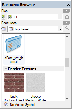
The record format appears in the Resource Browser, under the Record Format category. Like any resource, it can be shared between files using the export or import functionality of the Resource Browser.
Once the custom record format has been created, it is converted to an IFC Property Set and attached to an object, group, symbol definition, or symbol instance.
To assign the custom IFC data:
1. Select the object, group, or symbol for assignment of IFC data.
2. Select the IFC object type as described in “Assigning IFC Data to Objects” on page 1740.
3. Click OK.
The IFC Data dialog box opens.
4. Click Manage Custom Property Sets.
The Manage Custom Property Sets dialog box opens.
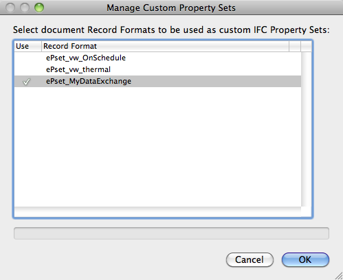
5. Click in the Use column to include a record format. Selected record formats display with a check mark.
6. Click OK to return to the IFC Data dialog box.
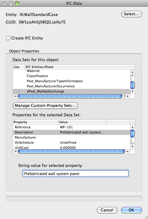
The selected custom record formats are listed as data sets in the IFC Entities/Psets list.
If there are any errors in the naming or formatting of any fields in the record format, the custom property set does not appear in the IFC Entities/Pset list. Internal checks ensure the integrity of the data and automatically reject any errors. Correct the errors by editing the record format from the Resource Browser, and try again.
7. Select the custom Pset and click in the Use column. A check mark indicates that the Pset is enabled and attached to the object.
8. Select the custom Pset properties and assign values to the selected properties.
9. Click OK to assign the IFC data to the object.
The IFC data can be reviewed or edited by clicking IFC Data from the Object Info palette of a selected IFC object or entity, or by selecting the object or entity and selecting AEC > IFC Data (Vectorworks Architect workspace) or Landmark >Architectural > IFC Data (Landmark workspace); see “Viewing and Editing IFC Data” on page 1742.
The custom property set is saved in the current file. To use a custom property set in another file or project, export the record format to another file and repeat the manage custom property sets process.
~~~~~~~~~~~~~~~~~~~~~~~~~
 Creating
IFC Schedules
Creating
IFC SchedulesBefore you export an IFC project, check that objects have appropriate IFC data associated with them. The following schedules with IFC data can be added to the drawing with the VA Create Schedule command, or you can create your own schedules (see “Records and Schedules” on page 1853).
• Objects with IFC Entity gives a count of IFC objects for each entity type on each layer. The object class, name, and type also display, if available.
• Objects with IFC Entity - Specific lists each IFC object, broken down by entity type (walls, slabs, roofs, doors, windows, stairs, and columns). The object layer, class, name, and description also display, if available.
• Objects without IFC Entity lists each non-IFC object. The object layer, class, type, and type name also display, if available.
Alternatively, from the Resource Browser, open the default architectural reports file from the [Vectorworks]\Libraries folder that is included with the Vectorworks Architect product (see “Bibliotecas de Recursos” on page 215). Drag the appropriate IFC worksheet to the drawing.
To edit the worksheets after they have been created, see “Using Worksheets” on page 1315.
~~~~~~~~~~~~~~~~~~~~~~~~~
 Importing
IFC Files
Importing
IFC FilesAn IFC project, including one which contains multiple buildings or large information sets, can be imported into a Vectorworks file. The units of the imported file are determined by the Vectorworks file. The presentation layers or CAD layers from an imported IFC file are assigned to corresponding Vectorworks classes.
Stories and elements in the IFC file can be filtered during the import, to remove irrelevant objects. Filtering an import can significantly lower the file size, making both the import process and subsequent collaboration more efficient.
To import an IFC file:
1. Select File > Import > Import IFC.
Alternatively, click the file to import and drag it into a window where a Vectorworks document is open.
2. Select the .ifc, .ifczip, or .ifcxml file to open, and click Open.
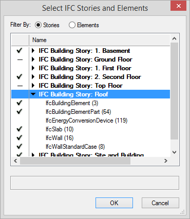
The Select IFC Stories and Elements dialog box opens.
3. All stories and elements are imported by default. If you want to apply a filter to the import, choose whether to filter by Stories or Elements.
4. If Stories is selected, a list of all stories in the document displays; a check mark to the left of each story indicates that it is to be imported. To omit one or more whole stories and any associated elements from the import, select the story and click to remove the check mark.
Alternatively, to omit only specific elements on specific stories from the import, click the disclosure arrow to the left of a story name to display the list of IFC elements associated with that story. Select the element(s) to be omitted and click to remove the check mark. The deselected elements are omitted only from that story.
On stories with a combination of selected and deselected elements for import, the check mark is replaced by a dash.
If Elements is selected, a list of all IFC object types in the file displays; the number of elements of each type displays in parentheses to the right of the object type. A check mark to the left of each item in the list indicates that all are to be imported by default. Select the element(s) to be omitted from the import, and click to remove the check mark. The deselected elements are not imported on any story.
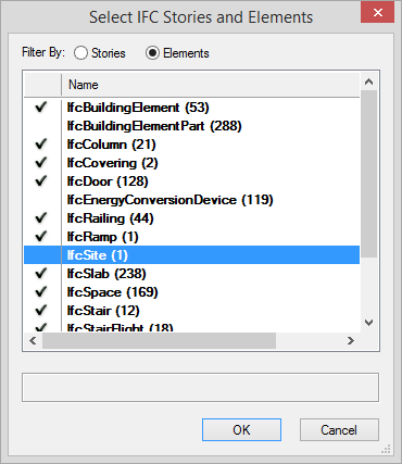
If you deselect some items from the elements list, and return to the stories list, stories that contain deselected elements display a dash rather than a check mark, indicating that some elements are not to be imported.
5. Click OK.
The IFC file is imported.
~~~~~~~~~~~~~~~~~~~~~~~~~
 Exporting
IFC Projects
Exporting
IFC ProjectsVectorworks project files can be exported to .ifc, .ifczip, and .ifcxml formats.
Export to IFC Versions 2x2 or 2x3 is supported. The export of a project to an IFC file is based on specifying the geometry and associated data needed for the use of the exported file. This specification is called a Model View Definition (MVD), a subset of all the geometry and data in a building model, depending on the workflow, or use of the geometry and data in another application, like design coordination, collision/clash detection, structural analysis, and element quantity analysis. MVDs can be created by international, national, or local groups that work to standardize information exchanges for such purposes. Vectorworks software supports the use of MVDs to automate the export, or allows the user to manually define a custom set of geometry and data to be exported.
To export a Vectorworks file to IFC:
1. Select File > Export > Export IFC Project.
The Export IFC Project dialog box opens.
2. Specify the overall project export options, site information, and author data for each pane of the Data tab. Many of the fields are required by the IFC specification; they are automatically mapped to their IFC equivalent for inclusion in the IFC file header information.
Click to show/hide the parameters.
3. Click the Layer Mapping tab to specify which layers to export, and the Story Name to assign to them at export. If specified, this includes the site model. For a project initially set up with stories, mapping is done automatically so that the layers assigned to the building stories are automatically included in the Mapped Layers list and are mapped to an appropriately named story (Vectorworks Architect required). Mapping can also be controlled manually.
Specify the associated building or site data for each of the mapped layers.
Click to show/hide the parameters.
4. Click OK to export the project.
Indicate the file name and location in the Save As dialog box.
~~~~~~~~~~~~~~~~~~~~~~~~~