Creating
Spaces with the Space Tool
Creating
Spaces with the Space ToolThe Vectorworks Architect product performs space planning and programming studies, and creates schematic floor plans.
These features can be combined in various ways depending on your preferred workflow:
• To begin the design process, draw the spaces. Reposition and reshape the spaces as needed to develop a schematic floor plan. Then create the walls automatically from those spaces.
• Begin with a solid model, and then create the exterior walls from the model.
• Create the walls first, and then create the space objects automatically to determine the areas enclosed by the walls.
• Using space programming, import an adjacency matrix that was provided by a client, and automatically create a bubble diagram and a stacking diagram. Reshape and reposition the space objects in the bubble diagram to create a floor plan, and then create the walls automatically from the spaces.
• Create the initial schematic design with polylines instead of spaces, and then convert the polylines to spaces.
• Create the model with stories, and associate the net/gross volume of the spaces along with the stories.
Use the Space tool to create a schematic floor plan. The Vectorworks Architect product can then automatically create walls from those spaces. To track room finish data on a schedule, add finish information to the spaces. If necessary, IFC data (including extended space properties used by the General Services Administration) can be attached to the spaces. The net and gross volume of a space can be associated with story elevation, so that as story layer levels change, the space volume adjusts accordingly.
If walls or polylines that represent spaces already exist in the drawing, use space planning commands to create spaces from the walls or polylines.
When creating and updating spaces, the visibility of walls can affect the spaces, depending on the situation and action:
• When creating spaces, only visible walls are taken into account
• When updating existing spaces (clicking Update Boundary from the Object Info palette), only visible walls are taken into account
• When existing spaces are regenerated, for example due to changed space labels, a new height value, or moved walls, wall visibility has no effect on automatically bounded spaces, because the spaces are already associated with the walls.
See “Editing Space Boundaries” on page 429 for more information.
~~~~~~~~~~~~~~~~~~~~~~~~~
Creating
Spaces with the Space ToolSpaces are path objects that have the characteristics of a building space or room, which include information such as the space name, number, finish information, and height. The space label, which is drawn using a pre-defined or user-defined symbol, can display not only name and number, but virtually any desired information. Space objects automatically calculate their area, volume, and perimeter.
The Room Name Simple tool (in the Dims/Notes tool set) creates a text label only; it does not attach room finish, area, IFC, or GSA information to a space object.
To draw a free-standing space with the Space tool, select either the Rectangle or the Polyline mode. If the walls are already drawn, select the Picked Walls mode or Inner Boundary mode to create a space bounded by visible walls.
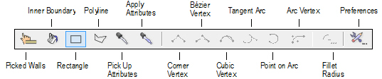
Mode |
Description |
|---|---|
Picked Walls |
Creates a space object based on a closed set of selected walls |
Inner Boundary |
Creates a space object in a clicked area that is bounded by visible walls |
Rectangle |
Draws a rectangular space object |
Polyline |
Draws a polyline space object; as with a polyline, select one of six types of control points for the vertices from the Tool bar |
Pick Up Attributes |
Picks up the attributes of a space that is clicked upon. The properties that are transferred can be customized; see “Space Settings: Advanced Settings Pane” on page 412 for details. |
Apply Attributes |
Transfers the space attributes that have been picked up with the Pick Up Attributes mode to a space that is clicked upon. Press the Ctrl key (Windows) or the Option key (Mac) when you click to toggle between the Pick Up Attributes and Apply Attributes modes. |
Corner Vertex |
For Polyline mode, creates the space using polyline segments with straight lines and angled vertices at the control points |
Bézier Vertex |
For Polyline mode, creates the space using polyline segments with curves pulled toward, but not touching the control points |
Cubic Vertex |
For Polyline mode, creates the space using polyline segments with curves that pass through the control points |
Tangent Arc |
For Polyline mode, creates the space using polyline segments that are tangent to the previous segment |
Point on Arc |
For Polyline mode, creates the space using polyline segments that are drawn by clicking three points: the start point, a point the arc passes through, and the end point |
Arc Vertex |
For Polyline mode, creates the space using polyline segments with curves that look like a fillet placed at the control points |
Fillet Radius |
For Polyline mode, sets the fillet radius when the Arc Vertex mode is selected |
Preferences |
Sets the default parameters that are used for each new space object |
Spaces can be automatically created by first selecting the enclosing walls or by clicking within the boundary of a closed set of visible walls. The spaces are automatically associated with their bounding walls.
Alternatively, select AEC > Space Planning > Create Spaces from Walls to create spaces from a set of enclosed walls on a specified design layer (see “Creating Spaces from Walls” on page 426).

To create a space within a selected set of visible walls:
1. Click the Space tool from the Space Planning tool set or the Building Shell tool set.
2. From the Attributes palette, set the 2D attributes for the space (fill, pen, opacity, and line thickness).
3. From the Tool bar, select Preferences. Set the default parameters for the space objects.
4. From the Tool bar, select Picked Walls mode.
5. Click on each wall that forms the wall set and press Enter, or click the check mark button on the Tool bar. The space is created with the attributes and settings you specified.
6. Add information specific to the space.

To create a space within a closed set of visible walls:
1. Click the Space tool from the Space Planning tool set or the Building Shell tool set.
2. From the Attributes palette, set the 2D attributes for the space (fill, pen, opacity, and line thickness).
3. From the Tool bar, select Preferences. Set the default parameters for the space objects.
4. From the Tool bar, select the Inner Boundary mode.
5. Click in an open area of the drawing that is bounded by walls; the walls must be visible, joined together, and on layers that have the same layer scale as the space layer. The space is created with the attributes and settings you specified.
6. Add information specific to the space.

To draw a space with the Space tool:
1. Click the Space tool from the Space Planning tool set or the Building Shell tool set.
2. From the Attributes palette, set the 2D attributes for the space (fill, pen, opacity, and line thickness).
3. From the Tool bar, select Preferences. Set the default parameters for the space objects.
4. From the Tool bar, either select the Rectangle mode, or select the Polyline mode and then select the type of control point for the polyline vertices.
5. Draw the space as follows:
• For a rectangular space, click to begin the rectangle, and then click again to finish the rectangle and create the space.
• For a polyline space, click to begin the polyline, and then click to set each polyline vertex. Click on the start point to end the polyline and create the space.
The space is created with the attributes and settings you specified.
6. Add information specific to the space.
After all spaces have been created, select specific spaces and add more information to them on the Object Info palette, such as a space name and room finishes. The items that are changed most frequently are available on the Shape tab. To access the full set of space properties, click the Settings button to open the Space Settings dialog box.
The properties that are available on the Object Info palette are determined by the Advanced Settings pane on the Space Settings dialog box. See “Space Settings: Advanced Settings Pane” on page 412 for details.
If several spaces need to have attributes in common, such as the same space name and room finishes, copy the attributes from an existing space and apply them to the other spaces.

To copy attributes to other spaces:
1. Click the Space tool from the Space Planning tool set or the Building Shell tool set, and then from the Tool bar, select Preferences.
2. From the Space Settings dialog box, select the Advanced Settings pane.
3. Select the attributes to transfer between spaces from the Eyedropper Transfer Properties window (see “Space Settings: Advanced Settings Pane” on page 412 for details).
4. Select the Pick Up Attributes mode from the Tool bar. Click the space with the attributes you want to transfer.
5. Select the Apply Attributes mode from the Tool bar, and click each space that should have those attributes.
Alternatively, press the Ctrl key (Windows) or the Option key (Mac) while you click to activate the Apply Attributes mode.
~~~~~~~~~~~~~~~~~~~~~~~~~
 Space Settings
Use the Space tool’s Preferences to set the default parameters for space objects before you create them, including the label style, automatic numbering, boundary calculations, and 3D graphic attributes. For maximum control over the display of spaces, you can set default classes for the label, label leader line, 2D attributes, 3D attributes, and the entire space object. Preference settings are an easy way to apply common, consistent settings to all spaces.
The space’s 2D graphic attributes are not taken from the Preferences settings. Instead, set the appropriate fill and pen styles in the Attributes palette before you create the spaces.
Once the spaces have been created, use the Object Info palette to edit the properties of individual spaces, including space name and occupant, room finishes, and any additional data attached to the space. The items that are changed most frequently are available on the Shape tab. To access the full set of space properties, click the Settings button to open the Space Settings dialog box.
The properties that are available on the Object Info palette are determined by the Advanced Settings pane on the Space Settings dialog box. See “Space Settings: Advanced Settings Pane” on page 412 for details.
To reduce the time required to regenerate space objects after properties are edited, Vectorworks only regenerates the space components that are changing and only recalculates the bounds of the spaces if necessary. To force the complete regeneration of edited space objects, select Tools > Utilities > Reset all Plug-Ins.
The fields that display on the Space Settings dialog box are slightly different, depending on whether you access the dialog box with the Preferences mode of the Space tool or with the Settings button on the Object Info palette.
The settings are grouped into several panes of related parameters. Select each group of parameters from the list in the left pane of the dialog box; the parameters display in the center pane.
The right pane of the dialog box always displays a preview of the space label(s) based on the current settings. To edit the appearance of any of the space labels (for example, to change the font size or the pen color), click the label’s Edit Layout button at any time.
A few controls can be edited directly from the Object Info palette, as described in “Space Properties” on page 413.
Click to show/hide the parameters.
Click to show/hide the parameters.
Click to show/hide the parameters.
Many parameters on this pane are available only if the space is connected to adjacent walls.
Click to show/hide the parameters.
Click to show/hide the parameters.
As many as three space labels can be independently formatted and positioned for each space. The Space Label 1 pane is available by default; to add the Space Label 2 and Space Label 3 panes to the dialog box, select Enable multiple labels on the Advanced Settings pane (see “Space Settings: Advanced Settings Pane” on page 412).
Click to show/hide the parameters.
Parameters to position the leader line for space label 1 are available by default; leader line parameters for space labels 2 and 3 are available only if Enable multiple labels is selected on the Advanced Settings pane. The leader lines’ class and appearance are set on the 2D Attributes pane (see “Space Settings: 2D Attributes Pane” on page 410).
Click to show/hide the parameters.
These settings apply to the space object only; the space label is a symbol, which can be edited with the Edit Layout button, or from the Resource Browser (see “Editing Existing Space Labels” on page 418).
Click to show/hide the parameters.
Click to show/hide the parameters.
Click to show/hide the parameters.
Once the room finish information is entered, add the Room Finish Schedule to the drawing file.
Click to show/hide the parameters.
Click to show/hide the parameters.
~~~~~~~~~~~~~~~~~~~~~~~~~
The space parameters are described in “Space Settings” on page 402. Only the parameters that are different are described here.
Click to show/hide the parameters.
 Using
Auto-Numbering
Using
Auto-NumberingThe Vectorworks Architect program can automatically number spaces as they are created, or you can enter numbers manually. If you use the auto-numbering feature, the Numbering pane of the Space Settings dialog box has additional features to customize numbers and to adjust numbers when needed.
You can create custom space numbers that contain information other than just a counter, such as the floor the space is on, or what zone the space is in.
To create, edit, or delete a number style:
1. Select the Space tool, and then click Preferences on the Tool bar.
2. On the Space Settings dialog box, select Numbering from the left pane to display the Numbering pane.
3. Click Edit Number Styles to add, edit, or delete the available number styles.
The Edit Number Style dialog box opens.
Click to show/hide the parameters.
4. Edit the number styles as follows:
• To add a new number style, type a style name into Space Number Style, and add a Prefix and/or Suffix if desired. Click Save; the number style is added to the Style Name/Style Definition/Saved in list.
• To edit a number style, select it from the Style Name/Style Definition/Saved in list and then edit the Prefix and/or Suffix as needed. Click Save to save the changes.
• To delete a number style, select it from the list and then click Delete.
5. When all editing is complete, click OK to close the Edit Number Style dialog box.
Occasionally the auto-numbering may need adjustment. For example, if a space is deleted after creation, one of the numbers will be missing from the sequence. If a space was duplicated, its number may be used twice for the same label type. The Vectorworks Architect program can help you detect and correct such problems.
To validate auto-numbering:
1. Select the space object.
2. From the Object Info palette, click the Settings button to open the Space Settings dialog box, and then select the Numbering pane.
3. Click Validate Auto-Numbering.
The Validate Auto-Numbering dialog box opens.
Click to show/hide the parameters.
4. If there is a message next to a space number, select it and then click the correction button that displays beneath the list.
Message |
Problem |
Correction |
|---|---|---|
missing |
A number in the sequence is missing |
Click Close Gaps to renumber all spaces that fall after the gap in the sequence |
Value invalid (< Start) |
The space’s current number is less than the start value |
Click Assign valid value to automatically renumber the spaces as needed |
(multiple) |
Multiple spaces have this number |
Click Increase by Increment to automatically renumber the space |
5. When all problems have been corrected, click OK.
~~~~~~~~~~~~~~~~~~~~~~~~~
 Editing
Lists of Space Names and Occupant Organizations
Editing
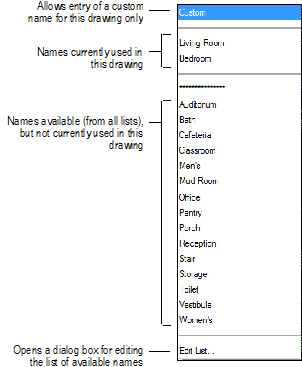
Lists of Space Names and Occupant OrganizationsThe Occupancy pane of the Space Settings dialog box has Space Name and Occup. Organization fields from which you can select values to assign to spaces. The names are collected from files in the Vectorworks application folder, your user folder, and any folder designated as your workgroup folder.
From the Vectorworks application folder, the default content from the standard occupant organization and space name libraries is always available. These lists are called “BOMA Standard Occupant Organizations.txt” and “Generic Space Names.txt.” You cannot modify these lists, but you can import and export items from them. Use the Space Settings dialog box to create custom versions of these lists, or to create new lists, as needed. Edits are automatically saved to your user folder.
In a workgroup environment, create space name and occupant organization lists and place them in a shared location. The folder structure must be the same as that of the default content libraries. See “Customizing the Space Settings” on page 424.
To edit a list of space names or occupant organizations:
1. Select the Space tool, and then click Preferences on the Tool bar.
Alternatively, select an existing space object, and from the Object Info palette, click the Settings button.
2. On the Space Settings dialog box, select Occupancy from the left pane to display the Occupancy pane.
3. Click Space Name or Occup. Organization, and select Edit List from the bottom of the list.
The appropriate editing dialog box opens.
4. Select the list to view.
• To view items from the list in the current document, click Active Document.
• To view items from a list external to the drawing file, click Default Folder, and then select from the List options. Lists from the Vectorworks application folder, your user folder, and your designated workgroup folder display.
5. Edit, import, or export items as described in the following table. The options available depend on what type of list you are editing.
Edit Function |
Applicable Files |
Procedure |
|---|---|---|
Rename the list |
User lists |
Click Rename, enter the new list name, and click OK. The list name in the edit dialog box changes. |
Change the list order |
Active document, user lists |
Click the item number and drag it up or down to the desired position. |
Add an item |
Active document, user lists |
Click New. • If the active document list or a user list is selected, a blank item is added to the current list. Enter a name in the Item Value field. • If a list from the application folder or a workgroup folder is selected, an alert displays, and you are prompted to add the item to a list in your user folder instead. Answer Yes to open a dialog box to add an item. Enter a name in the Item Value field. To create a new file, select Save to New File and enter a unique name. To add to an existing file, select Add to Current File and select a file from the pull-down list. Click OK to display the new item and list. |
Edit an item name |
Active document, user lists |
Select the item and enter the new name in the Item Value field. |
Delete an item |
Active document, user lists |
Select the item and click Delete. The item is removed from the list, and the items below it on the list are renumbered. |
Import items |
User, workgroup, and application lists |
Select one or more items and click Import. The items are added to the Active Document list. |
Active document, user, workgroup, and application lists |
Select one or more items and click Export to open the export dialog box. To create a new file, select Export to New File and enter a unique name. To add to an existing file, select Add to Current File and select a file from the pull-down list. Click OK to complete the export. |
6. Click OK to save the changes and close the edit dialog box. If you changed an external list, a message displays the path in your user folder where the edited file was saved; click OK.
7. Click OK to close the Space Settings dialog box.
~~~~~~~~~~~~~~~~~~~~~~~~~
 Customizing
Space Labels
Customizing
Space LabelsThe Vectorworks program provides several space labels, which you can use or modify as needed. You can also create new custom labels, import a space label symbol from another document, or convert a symbol in the current document into a space label.
Custom space labels are symbols that are designated as space labels from the Space Settings dialog box. Like any other symbol, by default a custom label is only available in the document in which it is created. To make a custom space label available from the Space Settings dialog box for all of your documents, use the Save as Default option to save the label to a template file. The Space Default template file is created in your user folder automatically, in [User Folder]\Libraries\Defaults\.
To share custom space labels with a workgroup, create a template file that contains the labels (see “Creating Space Labels” on page 418). Place the file in the workgroup’s default labels folder. The labels then display on the list of available symbols on the Space Label pane of the Space Settings dialog box. See “Customizing the Space Settings” on page 424.
Click here for a video tip about this topic (Internet access required).
~~~~~~~~~~~~~~~~~~~~~~~~~
 Editing
Existing Space Labels
Editing
Existing Space LabelsYou can easily make minor adjustments to an existing space label. For example, you might adjust the font style or color, or change the graphics that are included in the symbol.
To modify an existing space label symbol:
1. Do one of the following:
• From the Space Label pane of the Space Settings dialog box, select the label to be edited; a preview of it displays on the right side of the dialog box. Click Edit Layout to open the symbol editing window.
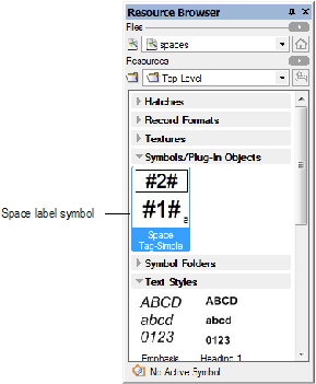
• If the label displays in the Symbols/Plug-in Objects group in the Resource Browser, select it and then select Resources > Edit. From the Edit Symbol dialog box, select the 2D Component option, and click Edit to open the symbol editing window.
2. In the symbol editing window, edit the text formatting, graphic components, and attributes of the symbol as needed. Note that a space label is a page-based symbol, which means that its size in the editing window is the same as it will be when inserted into the drawing.
3. When the changes are complete, click Exit Symbol.
4. The symbol definition and all instances of the label in the drawing are updated automatically.
~~~~~~~~~~~~~~~~~~~~~~~~~
 Creating
Space Labels
Creating
Space LabelsIf none of the available space labels are suitable, create a new label.
To create a new space label:
1. From the Space Planning tool set or the Building Shell tool set, select the Space tool.
2. From the Tool bar, click Preferences to open the Space Settings dialog box.
3. Select the desired space label pane, and click Manage Space Labels. The Manage Space Labels dialog box opens.
Item |
Description |
|---|---|
Symbols list |
The left side of the dialog box displays a list of all space label symbols currently available, along with the current status of each: • “Default” symbols are those available from default content, but not yet used in the drawing; once a default space label symbol is used, it is imported into the drawing file’s resources and the status becomes Specified. Default symbols cannot be renamed or deleted. • “Specified” symbols are currently used in the drawing. • “Unspecified” symbols are currently in the drawing file’s resources, but not yet used or saved as a default. |
Symbol preview |
The top right side of the dialog box displays a preview of the selected symbol; if a label field has not been defined yet, a red “Not specified” message displays on the image |
New Text Tag |
Opens the New Text Tag dialog box, to create a new space symbol; proceed with step 4
|
New Symbol Tag |
Opens the New Symbol Tag dialog box, to designate a symbol in the current document as a space symbol. |
Opens the Rename Label dialog box; enter a new name for the symbol and click OK. If the selected symbol has a “Default” status, a message displays that it cannot be renamed. |
|
Opens the Duplicate Label Symbol dialog box; enter a name for the duplicate symbol and click OK. |
|
Opens the Delete Space Label dialog box. Specify whether to delete the space symbol from the symbol library entirely, or to keep the symbol, but remove the space label definition from it (this removes the label from the list of current space label choices). Click OK to delete the label. If the selected symbol has a “Default” status, a message displays that it cannot be deleted. |
4. Click New Text Tag; the New Text Tag dialog box opens to the Data Fields tab.
5. All available data fields for spaces display in the list on the left. Select the fields to be used in the symbol, and click Add (or click Add All) to move them to the list on the right. To remove fields from the symbol list, select them and click Remove (or click Remove All). Alternatively, double-click a field name to move it from one list to the other.
6. In the list of selected symbol fields on the right, each field is assigned a sequential number, which corresponds to a variable in the symbol layout (for example, #2#). To change a field’s number, click its number column, and drag the field up or down to the desired location on the list.
7. Select the Attributes tab to specify how all fields in the symbol will display.
Item |
Description |
|---|---|
Font |
Select a font for the field text from the list of fonts available on the system |
Size |
Select a font size from the list of standard sizes available in points. To enter a custom point size, or to enter a size in different units, select Set Size to open the Set Text Size dialog box. Enter a Size, and then select the appropriate Unit: Points, Page Millimeters, or Page Inches. |
Style |
Select a style for the field text from the list of styles available. On Mac, select Custom Style to open the Custom Style dialog box, to specify a different combination of styles. |
Alignment |
Select a type of alignment for the field text: Left, Center, Right, or Standard (justify) |
Fill |
Select a fill for the background of the field text objects: None, Pattern, or Solid. Or, to assign the fill by text object class, select Class Style. |
Color |
If a Solid fill was selected, select the fill color |
Pattern/Fore/Back |
If a Pattern fill was selected, select the Pattern, and the foreground and background colors |
Text Color |
Select a color for the field text |
8. Click OK to save the changes and return to the Manage Space Labels dialog box. Click OK again to return to the applicable space label pane.
9. Complete the definition of the label.
10. To save the label to your template, select the Save as Default option.
11. To change the appearance of the label (for example, to rearrange the data fields or to add graphic elements), click Edit Layout to open the symbol editing window.
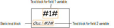
The symbol is a group object, in which each defined field is a text block that contains text in the following format: #(natural number)#. You may ungroup the blocks and move them or change their attributes, but do not change the contents of the text blocks.
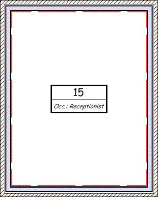
In the following example, the top part of the symbol is a center-aligned text block that contains a variable for field 1; the Space Number will be assigned to this field. The bottom part of the label has a text block that contains a variable for field 2; the Occupant Name field will be assigned to this field. Another text block was added, which serves as a label for the occupant name. A rectangle and a line were also added to enhance the label.
12. When the edits are complete, click Exit Symbol. The new label is now available to assign to spaces for this document.
~~~~~~~~~~~~~~~~~~~~~~~~~
 Converting
Symbols into Space Labels
Converting
Symbols into Space LabelsIf you already have a symbol you want to use, you can convert it for use as a space label.
To convert a symbol into a space label:
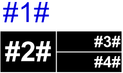
1. Ensure that the symbol includes a text block for each piece of space object data you want to display on the label. The text in each field block should be in the following format: #(natural number)#. The example below has four fields. Apply the font, size, style, alignment, and fill and pen style desired to each text block.
Also, ensure that the space label symbol is specified as having world-based units (not page-based).
2. From the Space Planning tool set or the Building Shell tool set, select the Space tool.
3. From the Tool bar, click Preferences to open the Space Settings dialog box.
4. Select the desired space label pane, and click Manage Space Labels. The Manage Space Labels dialog box opens.
5. Click New Symbol Tag; the New Symbol Tag dialog box opens.
6. The available symbols and symbol folders in the current document display; symbols already defined as space labels do not display. Locate and select the symbol to be used for the new label, and click OK.
7. On the Manage Space Labels dialog box, notice that the preview window shows that the fields are not specified yet. Click OK to return to the Space Settings dialog box.
8. Complete the definition of the data fields. The new label is now available to assign to spaces for this document.
9. To save the label to your template, select the Save as Default option.
~~~~~~~~~~~~~~~~~~~~~~~~~
 Room Finishes
The Room Finishes pane of the Space Settings dialog box has Ceiling, Base Trim, Floor, and North/South/East/West Wall fields from which you can select values to assign to spaces. The names are collected from files in the Vectorworks application folder, your user folder, and any folder designated as your workgroup folder.
From the Vectorworks application folder, the default content from the room finish libraries is always available. You cannot modify these lists, but you can import and export items from them. Use the Space Settings dialog box to create custom versions of these room finish lists, or to create new lists, as needed. Edits are automatically saved to your user folder.
In a workgroup environment, create room finish lists and place them in a shared location. The folder structure must be the same as that of the default content libraries. To edit a room finish list:
1. Select the Space tool, and then click Preferences on the Tool bar.
2. On the Space Settings dialog box, select Room Finishes from the left pane to display the Room Finishes pane.
Alternatively, select one or more existing space objects and click Assign Room Finish in the Object Info palette to open the Assign Room Finishes dialog box. (If the button is not enabled, select On Room Finish Schedule.) If room finishes are different for multiple selected space objects, the options display as a blank. Any edits to that parameter affect all of the selected spaces.
3. Click Edit Finishes to add, edit, or delete the available room finishes.
The Edit Room Finishes dialog box opens.
4. Select the list of room finishes to view.
• To view items from the current document, click Document Finishes, and then select from the Location options (ceiling, walls, baseboard, or floor).
• To view items from a list external to the drawing file, click Default Finishes, and then select from the Location options. Lists from the Vectorworks application folder, your user folder, and your designated workgroup folder display.
5. Edit, import, or export items as described in the following table. The options available depend on what type of list you are editing.
Edit Function |
Applicable Files |
Procedure |
|---|---|---|
Rename the list |
User lists |
Click Rename, enter the new list name, and click OK. The list name in the edit dialog box changes. |
Change the list order |
Active document, user lists |
Click the item number and drag it up or down to the desired position. |
Add an item |
Active document, user lists |
Click New. • If an active document list or user list is selected, a blank item is added to the current list. Enter a Key and Description. • If a list from the application folder or a workgroup folder is selected, an alert displays, and you are prompted to add the item to a list in your user folder instead. Answer Yes to open a dialog box to add an item. Enter a Key and Description. To create a new file, select Save to New File and enter a unique name. To add to an existing file, select Add to Current File and select a file from the pull-down list. Click OK to display the new item and list. |
Edit an item Key or Description |
Active document, user lists |
Select the item and enter the new value in the appropriate field. The Key is the ID that displays for the selected finish in the space label (if applicable), Room Finish Legend, and Room Finish Schedule. Description text displays for the selected finish in the Room Finish Legend. |
Delete an item |
Active document, user lists |
Select the item and click Delete. The item is removed from the list, and the items below it on the list are renumbered. |
Import items |
User, workgroup, and application lists |
Select one or more items and click Import. The items are added to the appropriate list in the current document. |
Export items |
Active document, user, workgroup, and application lists |
Select one or more items and click Export to open the export dialog box. To create a new file, select Export to New File and enter a unique name. To add to an existing file, select Add to Current File and select a file from the pull-down list. Click OK to complete the export. |
6. Click OK to save the changes and close the edit dialog box. If you changed an external finish list, a message displays the path in your user folder where the edited file was saved; click OK.
7. Click OK to close the Space Settings dialog box.
~~~~~~~~~~~~~~~~~~~~~~~~~
 Assigning
a Room Finish
Assigning
a Room FinishRoom finishes can be applied to space objects (see “Creating Spaces from Existing Walls” on page 401). The information displays in the Room Finish Schedule and in the Room Finish Legend (see “Records and Schedules” on page 1853).
To assign finishes to a space object:
1. Select an existing space object.
2. In the Object Info palette, select On Room Finish Schedule to add the finish information to the Room Finish Schedule. Click Assign Room Finish.
The Assign Room Finishes dialog box opens.
Alternatively, click Settings to open the Space Settings dialog box, and select the Room Finishes pane.
Click to show/hide the parameters.
3. Select the desired finishes for each part of the room and click OK. The information is associated with the selected space object.
4. The Room Finish Schedule can be added to the drawing from the VA Create Schedule command or the Resource Browser. From the Resource Browser, open the default architectural reports file from the [Vectorworks]\Libraries folder that is included with the Vectorworks Architect product. Drag the Room Finish Schedule worksheet to the drawing. The worksheet is populated with information from the objects in the current drawing.To add a legend for the Room Finish Schedule, use the Create Rm Finish Legend command.
~~~~~~~~~~~~~~~~~~~~~~~~~
 Customizing
the Space Settings
Customizing
the Space SettingsWhen you edit the space name, occupant organization, and room finish lists in the Vectorworks Architect product, the changes are saved to text files in your user folder. In a workgroup environment, you can create a set of files that contain standard settings for your office and share them with coworkers over a network.
To access the shared content, another Vectorworks user simply designates that folder as a workgroup folder in his or her Vectorworks Preferences. Then, when the user creates spaces in a drawing, the space name, occupant organization, and room finish list items are collected from files in the Vectorworks program folder, the user folder, and any folder designated as a workgroup folder.
To create custom space settings:
1. In the Space tool’s preferences, customize the space name, occupant organization, and room finish lists as needed. The appropriate files are created in the user data folder specified in your Vectorworks preferences (see “User Folders Preferences” on page 55).
2. To share the custom files with a workgroup, put the files on the network in a workgroup folder. When coworkers set up this workgroup folder in their Vectorworks preferences, they also have access to the files (see “Sharing Custom Content Using Workgroup Folders” on page 212). The folder structure must be the same as the default content room finish, standard occupant organization, and space name libraries provided with the Vectorworks Architect product in [Vectorworks]\Libraries. For example, to add a custom space name library, place the file in your workgroup default space name folder: [Workgroup]\Libraries\Defaults\Space - Space Name.
3. To share custom space labels with a workgroup, save the labels to your template file (see “Creating Space Labels” on page 418). Place the file in the workgroup’s default space stamp folder.
4. Remove the custom files you created from your user folder if you intend to use the workgroup settings. Remember that the contents of the user folder have priority over the contents of the workgroup folder.
~~~~~~~~~~~~~~~~~~~~~~~~~
 GSA Data
The General Services Administration in the United States has set deliverables standards that require that projects be delivered in IFC format. In addition, they require that certain additional GSA-specific data be included with spaces.
To specify GSA data for a space object:
1. Select an existing space object.
2. In the Object Info palette, click Settings to open the Space Settings dialog box.
3. Select the Advanced Settings pane, and then click Enable GSA.
4. Select the Occupancy pane, and then click GSA Occupancy.
The GSA Occupancy dialog box opens.
Click to show/hide the parameters.
5. Enter the GSA data for the space object and click OK.
6. When the drawing is complete and all required GSA data has been entered, select File > Export > Export IFC Project to save the file in IFC format.
A GSA spatial program BIM has some specific modeling requirements. Use the following guidelines to create an optimal IFC export from the Vectorworks program, that is compatible with all GSA guidelines and standards.
• Reduce, eliminate, or deactivate (by hiding appropriate classes) the 3D components of objects that do not contribute to the spatial definition of the model. While the IFC data format does support a number of “non-spatial” or “non-structural” items, they are not required for the current GSA spatial program BIM.
• Ensure that all wall intersections are correctly configured, so that an automatically bound space object can properly detect room extents.
• Ensure that all space objects have the following settings in the Object Info palette:
• 2D Boundary Display (2D Boundaries & Area section) is set to “Net Boundary”
• 2D Net Boundary Definition (2D Boundaries & Area section) is set to “Inside Face of Walls”
• Show 3D (3D Boundaries section) is enabled
• The Volume Display of the 3D boundary is set to “Net,” and the height is set to properly represent the full height of the space, either manually, or based on story-aware settings
The GSA requires a “net” space boundary that wraps around pilasters and free-standing concrete columns, excluding them from the area calculations. However, the space boundary should not wrap around steel columns, or columns embedded in a wall; these should be ignored.
To create a GSA BIM-compatible vertical support, use either the Column or Pilaster tool. A column is restricted to symmetrical square or oval plan geometry. A pilaster must be set to Architectural, or Structural and Architectural, to comply with GSA requirements. The space boundary will wrap around the extents of these structures.
Columns that are exposed steel wide flanges or H-shapes do not need to be excluded from the GSA BIM area. If a structural steel column is required, use extruded plan geometry inside a hybrid symbol to create the column; the column will be recognized as 3D geometry, but it will not be excluded from the GSA BIM area in the space object.
Per GSA guidelines, a shaft that has a floor penetration greater than nine square feet should be designated as its own space.
If this shaft is bounded completely by walls, simply create a space object inside the shaft. If the shaft is not bounded by walls, use the Wall tool’s <Virtual wall> style to create a boundary; once the shaft is surrounded with virtual walls, create spaces in the room and shaft.
~~~~~~~~~~~~~~~~~~~~~~~~~
 Creating
Spaces from Walls
Creating
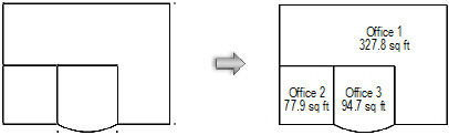
Spaces from WallsFloor plans can be created by first creating walls, and then automatically creating spaces to determine the area of each room or the gross area defined by the wall perimeter.
To create spaces from walls:
1. Create the walls and ensure that they are properly joined.
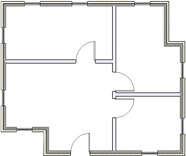
2. From the Attributes palette, set the 2D attributes for the spaces (fill, pen, opacity, and line thickness).
3. Select the Space tool, and from the Tool bar, select Preferences. Set the default parameters for the space objects.
4. Select AEC > Space Planning > Create Spaces from Walls. The Create Spaces from Walls dialog box opens. Specify how to create the spaces, the minimum area for creating spaces, and their location.
Click to show/hide the parameters.
5. Click OK to create the spaces on the destination layer.
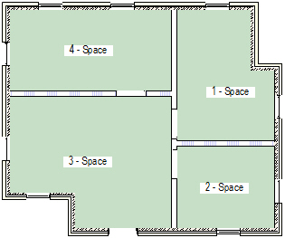
Spaces are created for all areas enclosed by walls, or for the gross area defined by boundary of the walls. Default room name information is set and should be edited to complete the floor plan.
After the spaces are created, the original walls can still be modified. To update the spaces to conform to the new walls, select the Create Spaces from Walls command again. The existing spaces are reshaped without losing any space parameters that have already been specified.
If the original spaces were not drawn perfectly straight, select the Create Walls from Spaces command with the Constrain Straight Walls option. Now that the walls are straight, select the Create Spaces from Walls command to straighten the spaces.
~~~~~~~~~~~~~~~~~~~~~~~~~
 Creating
Spaces from Polylines
Creating
Spaces from PolylinesDuring the initial stages of a design, it may be easier to work with polylines instead of spaces. Use the Modify > Add/Clip/Intersect/Combine into Surface commands to modify the polylines to create the desired shapes. Once the polyline shapes are finalized, convert them into spaces to take advantage of the additional features that space objects provide, such as labels, area calculations, room finishes, and so on.
To convert polylines into spaces:
1. From the Attributes palette, set the 2D attributes for the spaces (fill, pen, opacity, and line thickness).
2. Select the Space tool, and from the Tool bar, select Preferences. Set the default parameters for the space objects.
3. Select the polylines to convert into spaces. This command also converts rectangles, rounded rectangles, polygons, arcs, circles, and ovals into spaces.
4. Select AEC > Space Planning > Create Spaces from Polys. The selected items are converted into spaces.
Another option is to draw a polyline and then select the Create Objects from Shapes command (see“Creating Polylines” on page 294 and “Creating a Stacking Diagram” on page 438).
~~~~~~~~~~~~~~~~~~~~~~~~~
 Getting Floorplan Information
from a Solid Model
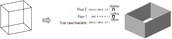
Getting Floorplan Information
from a Solid ModelIf a solid model has been used to develop a massing study, the Vectorworks Architect product can extract information from the model to begin work on the floorplans. Specifically, gross area polylines can be created automatically for each building level directly from the solid model with the Model to Floorplan command. A stacking diagram can display the sum of the areas of these polylines, which makes it easy to determine the amount of floor area provided by a solid model before creating the floorplans. In addition, exterior walls can be created automatically. If the model changes after the polylines and walls are created, run the Model to Floorplan command again to update the polylines and walls.
To create a floorplan from a model:
1. Select the model. The solid model should be a CSG solid (addition, subtraction, union), solid primitive (sphere, hemisphere, cone, cylinder), extrude, or multiple extrude.
This command cannot be used in Top/Plan view. Select the model from a 3D view.
2. Select AEC > Space Planning > Model to Floorplan.
The Model to Floorplan dialog box opens. Specify the layers to include and set the type of floorplan elements to create.
Click to show/hide the parameters.
3. Click OK to create the floorplan objects. If selected, polylines, walls, and a stacking diagram are placed on the drawing. To update the floorplan objects based on model changes, select the Model to Floorplan command again.
~~~~~~~~~~~~~~~~~~~~~~~~~
 Editing
Space Boundaries
Editing
Space BoundariesOnce a space is created, its boundary is edited differently depending on the current Auto-Boundary setting.
• If Auto-Boundary is enabled, the space is associated with a set of walls, regardless of whether the walls are visible. When the walls that surround the space change, in many cases, the space updates automatically.
• If Auto-Boundary is disabled, the space must be edited directly as a path object.
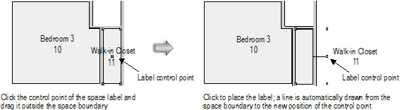
Each space has a control point that indicates the label location. If the space is auto-bounded, it also has a separate “anchor” control point that locates the space within its boundary. The anchor control point is typically in the center of the space’s bounding box, so it may be directly on top of the label control point. (If you create the space with Inner Boundary mode, the anchor is placed where you click to create the space.)
To move a label or an anchor, click the control point and drag it to a new location; click again to move the point. If a label is moved outside of the space boundary, a line is drawn to connect the label to the space automatically.
To edit a space with Auto-Boundary enabled:
1. Add, delete, or move the associated walls.
2. The spaces and labels update automatically, unless you are adding a new wall that affects an existing space or removing a wall that surrounds a space.
• If walls have been moved, the wall settings (thickness or components) have changed, or you move, edit, or delete an associated column or wall feature, the associated space object(s) and labels update automatically.
• If walls that are associated with a space are deleted, the space changes from an auto-bound space to a manual space. The space can be associated with new walls.
• If walls have been added, update the space object(s). Select one or more spaces, and then click Update Boundary from the Object Info palette. The location of the updated space is based on the position of the anchor point; other areas created by the dividing wall remain empty.
Alternatively, select AEC > Space Planning > Update Space Boundaries to update all spaces, whether or not they are selected.
3. The boundary of the space adjusts to match the surrounding walls; if the space label anchor point is now outside the space, a line is drawn automatically from the label to the space.
In cases where architects may have adjacent spaces in a design that are not explicitly separated by an actual wall, the <Virtual wall> wall style (a wall without width or height) gives the user a boundary for space objects to see when Auto-Boundary is enabled, primarily for IFC export.
To edit a space with Auto-Boundary disabled:
• To add, subtract, and change vertices, edit the polyline with the Reshape tool.
• The space object is a path object and some parameters cannot be edited directly from the Object Info palette. To make changes to the space path object, including changing its dimensions, select Modify > Edit Space. For example, you can reshape, add, clip, intersect, and combine into surfaces. Click Exit Path to return to the drawing.
Auto-bounded spaces can be converted to manual mode, releasing them from their association with walls.
To convert auto-bounded spaces to manual spaces:
1. Select the auto-bounded space. In the Object Info palette, the Auto-Boundary mode displays Auto-Bounded.
2. Select Manual from the Auto-Boundary list.
The space is disassociated from its wall set, though it remains in place.
Manually bounded spaces can be converted to auto-bounded mode by automatically associating them with the surrounding walls.
To convert manual spaces to auto-bounded spaces:
1. Select the manual space(s). In the Object Info palette, the Auto-Boundary mode displays Manual.
2. Select Auto-Boundary from the Auto-Boundary list.
The space object(s) is regenerated using the anchor point(s) to find the surrounding walls and associate them with the space(s).
Manually drawn spaces can be associated with a set of walls, converting them to auto-bounded mode. Similarly, an auto-bounded space can be associated with a new set of walls by this method.
To convert manual spaces to auto-bounded spaces:
1. Select the manual space. In the Object Info palette, the Auto-Boundary mode displays Manual.
2. Select Pick Boundary from the Auto-Boundary list.
The Space tool is automatically activated, and Inner Boundary mode is selected (Picked Walls mode can also be selected).
3. For Inner Boundary mode, click in an open area of the drawing that is bounded by walls. For Picked Walls mode, click on each wall that forms the wall set and press Enter, or click the check mark button on the Tool bar.
4. The manual space is associated with the wall set. Its location and size may change as it is bounded by the wall set.
~~~~~~~~~~~~~~~~~~~~~~~~~