Todos os produtos Vectorworks possuem ferramentas e comandos para desenhar paredes retas e curvas. Algumas dessas ferramentas e comandos no Vectorworks Design Series são similares àquelas disponíveis no Vectorworks Fundamentals, mas com recursos adicionais necessários para o design arquitetônico. As paredes podem ser desenhadas usando as ferramentas Parede Reta ou Parede Curva, ou criadas automaticamente a partir de objetos existentes no desenho incluindo espaços, polígonos e formas. O Vectorworks Architect e Landmark também oferecem o recurso de criar paredes cortina.
Vectorworks Fundamentals |
Vectorworks Architect, Landmark ou Spotlight |
|---|---|
Ferramentas Parede e Parede Curva localizadas no conjunto de ferramentas Paredes |
Ferramentas Parede e Parede Curva localizadas no conjunto de ferramentas AEC, com recursos adicionais no Vectorworks Architect e Landmark |
Modificar > Criar Polígonos de Paredes |
AEC > Criar Polígonos de Paredes Landmark > Arquitetônico > Criar Polígonos de Paredes Spotlight > Arquitetônico > Criar Polígonos de Paredes |
Modificar > Criar Paredes de Polígonos |
AEC > Criar Objetos de Formas (com recursos adicionais) Landmark > Criar Objetos de Formas Modificar > Criar Objetos de Formas no Spotlight |
|
AEC > Planejamento de Espaços Criar Paredes de Espaços |
~~~~~~~~~~~~~~~~~~~~~~~~~
Use as ferramentas de parede para desenhar paredes retas ou curvas, ou se você estiver usando o Vectorworks Architect ou Landmark, paredes cortina, e para juntar estas paredes a outras paredes. Cada segmento de parede é tratado como se fosse um objeto separado. Você pode juntar as paredes automaticamente ao desenhá-las, ou juntá-las após o desenho usando uma das opções de junção. Outros recursos de parede incluem adicionar traços dos componentes e preenchimentos a paredes, adicionar fechamentos e guarnições, e inserir símbolos (como portas e janelas) a elas. Você também pode adicionar e remover os picos em uma parede, se a elevação mudar de uma ponta à outra da parede.
Parâmetros adicionais de paredes estão disponíveis somente no Architect e no Landmark. Estes produtos oferecem o recurso de criar, salvar e usar estilos de paredes e de criar novas classes de paredes ou de componentes durante a criação e edição de paredes. No Vectorworks Architect, as paredes e os seus componentes também oferecem o recurso de definir os limites de topo e base de acordo com os níveis do andar atual, ou os níveis do andar acima ou abaixo do andar atual da parede.
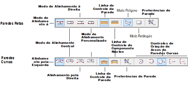
Existem quatro formas de se posicionar paredes em relação à linha de controle. A linha de controle pode ser definida em relação à parede ou a um componente de núcleo opcional. Paredes retas podem ser desenhadas no modo Polígono ou Retângulo. Estes modos são ativados pelos botões na barra de ferramentas.
Modo |
Descrição |
|---|---|
Alinhamento pela Esquerda |
As paredes serão desenhadas ao longo de sua face esquerda (no sentido de criação) |
Modo de Alinhamento Central |
As paredes serão desenhadas pela sua linha de eixo |
Alinhamento pela Direita |
As paredes serão desenhadas ao longo de sua face direita (no sentido de criação) |
Modo de Alinhamento Personalizado |
Neste caso as paredes serão desenhadas a partir de uma distância personalizada (Dist. Controle); muito útil quando desenhar paredes com Cavidadess |
Linha de Controle da Parede |
Permite definir a linha de controle em relação a parede |
Linha de Controle do Componente Núcleo |
Permite definir a linha de controle em relação ao componente da parede definido como o componente de núcleo nas preferências da parede |
Modo Polígono |
Desenha um sistema de parede ou parede reta, clicando em cada canto para criar uma forma personalizada, semelhante à ferramenta Polígono |
Modo Retângulo |
Desenha um sistema de parede retangular com dois cliques, semelhante ao canto da ferramenta Retângulo para o modo de Canto a Canto |
Preferências das Paredes |
Define os parâmetros físicos da parede |
Controle de Criação de Arcos de Paredes Curva |
Selecione o método de criação do arco para usar quando estiver desenhando paredes arredondadas; para mais informações dos modos de criação dos arcos, veja “Criando Arcos” na página 289 |
Veja “Direção da Parede” na página 501 para mais informações sobre como o ponto inicial e a direção de desenho da parede afetam os lados interno e externo da parede.
~~~~~~~~~~~~~~~~~~~~~~~~~
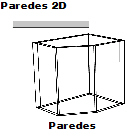
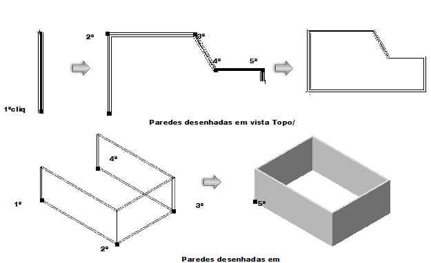
A ferramenta Parede cria um objeto híbrido representativo de uma parede, que possui simultaneamente tanto a parte 2D quanto a 3D do elemento. Paredes podem ser desenhadas tanto na vista Topo/Panta quanto na vista 3D.
Crie parades desenhando-as com o mouse, ou com o mouse e a Barra de Dados (veja “Usando a Barra de Dados” na página 121). O procedimento a seguir assume que as paredes sejam desenhadas com o mouse.

Para criar uma parede reta:
1. Selecione a ferramenta Paredes no conjunto de ferramentas Paredes.
• Fundamentals: Conjunto de Ferramentas Parede
• Design Series: Conjunto de Ferramentas Building Shell
2. Clique no botão de modo Deslocamento que você deseja usar (veja “Criando Paredes” na página 493).
3. In the Vectorworks Architect or Landmark product, to draw with an unstyled wall, select <Unstyled> from the Wall Style list on the Tool bar. If the desired styled wall resource has already been created, select it from the Tool bar list or double-click on the resource in the Resource Browser and proceed to Step 6.
4. Clique o botão de Preferências da Parede na Barra de Ferramentas.
A janela de diálogo Preferências da Parede aparecerá. Ela também pode ser usada para mudar as definições de paredes depois que você tiver começado a desenhar, e então os parâmetros podem ser definidos depois na paleta Info de Objetos.
Clique para mostrar / ocultar os parâmetros.
5.Clique Editar Atributos de Parede para especificar os atributos da parede.
A janela de diálogo de Atributos de Parede irá abrir. Os atributos de uma parede sem estilo é inicialmente um conjunto de parâmetros mostrados pela Paleta de Atributos. Caso eles sejam modificados aqui, a Paleta de atributos irá refletir as mudanças nos atributos da parede selecionada (após sair da janela de Preferências de Parede).
Preenchimento, traço e opacidade podem ser definidos através da classe associada à parede ao invés de usar os atributos da janela de Atributos de Parede. Caso a classe da parede seja alterada mais tarde, a parede irá alterar automaticamente para refletir os atributos da nova classe. Os atributos da parede não podem ser sobrepostos de uma forma individual (por exemplar); caso o estilo de uma parede use os atributos da classe, todas as paredes com este estilo terão que usar os atributos da classe. No entanto, paredes com o mesmo estilo podem ser posicionadas em diferentes classes.
Clique para mostrar / ocultar os parâmetros.
6. Clique OK para retornar para a janela de Preferências de Parede. Caso deseje adicionar componentes internos a sua parede, clique no botão Novo Componente para definir cada componente (veja “Creating Wall Components” na página 508). A Espessura Total será definida pela espessura dos componetes de parede.
In the Vectorworks Architect and Landmark products, wall components can be assigned to a class; this allows maximum flexibility since the component classes can be shown or hidden separately from the wall class. Select a class for the wall component to control its appearance and visibility. The classes present in the drawing are listed; alternatively, create a new class by selecting New, or select the class named <Object Class> which places the component in the same class as the wall. By default, components are assigned to the wall class.
In the Vectorworks Fundamentals product, wall components are automatically assigned to the <Object Class> and are always in the same class as the wall.
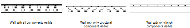
When a component is in an invisible class, its fill and lines are hidden. Invisible components on the interior and exterior of a wall cause the wall’s lines and fill to adjust to the visible components only, making the wall appear thinner than its actual width. This allows walls to show only their structural components, for example. If all components are invisible, the wall displays at its full thickness, without components.
The Hide Details preference can be used to hide wall components based on scale (Vectorworks Design Series required); see “Hiding Wall Components” na página 512.
7. Click the Insertion Options tab to set the wall insertion options.
Curtain walls have slightly different parameters; see “Creating Curtain Walls” na página 517.
Click to show/hide the parameters.
8. Clique na tab Texturas para seleciona quais texturas serão aplciadas nas diferentes partes da parede (requer Renderworks).
Texturas das paredes cortina são controladas pelos ajustes dos perfis e dos painéis na aba Definição; veja “Creating Curtain Walls” na página 517.
Clique para mostrar / ocultar os parâmetros
Parâmetro |
Descrição |
|---|---|
Usar Texturas dos Componentes |
Permite usar na parede as texturas definidas para os componentes da parede Esta opção também pode ser usada em uma parede existente através da aba Apresentar da paleta Informações de Objeto |
Usar Texturas do Objeto |
Usa as texturas definidas abaixo nas partes da parede (veja “Aplicando uma Textura a um Objeto” na página 1526 |
Parte |
Aplica a textura selecionada no campo Textura à parte da parede |
Reverter para Total |
Se você atribuiu uma textura a uma parte mas quer que ela receba a textura Total, clique na parte e em seguida cilque em Reverter para Total. A parte será colocada novamente abaixo da divisória e (a partir do Total) será exibido como o nome da textura. |
Textura |
Permite aplicar a textura à parte selecionada. As texturas também pode ser aplicadas a partir da aba Apresentar na paleta Informações de Objeto. As texturas aplicadas a partir da paleta Informações de Objeto têm precedência sobre as texturas aplicadas aqui. |
Sem Textura |
Não aplica uma textura à parte selecionada |
Textura da Classe |
Usa a textura definida pela classe da parede. Quaisquer paredes que utilizem este tipo utilizarão as texturas da classe naquela parte da parede (a menos que essa opção tenha sido alterada manualmente). Você também pode escolher a Textura da Classe para a parede selecionada usando a aba Apresentar da paleta Informações de Objeto. |
Escolher Textura |
Permite escolher a textura da parte selecionada a partir dos recursos default ou dos recursos do arquivo atual (veja “Resource Libraries” na página 215). As texturas aplicadas aqui têm precedência sobre as texturas da classe do objeto. |
9. Clique na aba Dados (Vectorworks Architect/Landmark requeridos) para especificar informações do registro da parede, o qual é IFC-compliant e possa ser incluído em um cronograma de paredes. Estes campos são opcionais; entre informações somente onde precisar.
10. Quandos os parâmetros da parede estiverem especificados, e muitas mudanças tiverem sido salvas em um recurso de estilo de parede se desejado (Vectorworks Design Series requirido), clique OK.
Nas versões Design Series, um estilo de parede é salvo como um recurso no arquivo, e este aparecerá tanto no Administrador de Recursos como na lista de Estilos de Paredes na Barra de Ferramentas. Veja “Creating Wall Styles” na página 503
11. Se o modo Poligonal estiver selecionado, clique no ponto inicial do primeiro segmento da parede.
12. Clique para finalizar o primeiro segmento de parede.
Para continuar a criação de parede, clique no final de cada segmento de parede adicional.
13. Duplo-clique para finalizar a parede se o ponto inicial e final não estiverem na mesma localização; caso contrário, clique no ponto inicial (uma dica do SmartCursor será mostrada) para finalizar a parede.
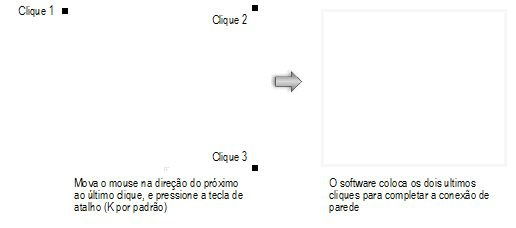
Alternativamente, após completar tudo menos o clique final, pressiona a tecla de atalho "K" para fechar automaticamente a sequencia de segmentos de paredes. Veja “Modificando Atalhos de Atração e Modos” na página 1833 para alterar o atalho.
Quando desenhar uma rede de paredes regulares, como um retangulo, mova o mouse na direção próxima ao ultimo clique e aperte o atalho de teclado antes de clicar; o programa irá extrapolar o alinhamento correto e posição do ultimo clique, e completar a rede de paredes.
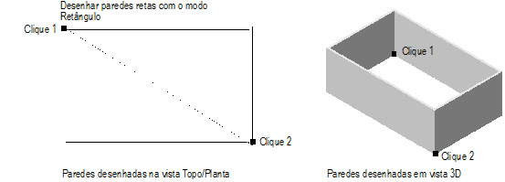
14. Se modo Retangulo estiver selecionado, clique no ponto inicial da parede; esse ponto se tornará o canto do sistema retangular de paredes. Mova o mouse para o canto oposto até que o tamanho desejado seja exibido.
15. Clique para definir o ponto de canto do sistema de paredes. Quatro paredes serão criadas.
Quando a preferencia do Vectorworks Unção Automática de Paredes estiver ativada, paredes desenhadas em modo retangulo que sobrepõem ou tocam alguma outra, interagem. Dessa forma sistemas complexos de paredes poderão ser desenhados de forma rápida. Veja “Automatically Joining Walls in Rectangle Mode” na página 539 para as regras que definem essas interações.
As propriedades de parede podem ser editadas na paleta de Informações de Objeto.
~~~~~~~~~~~~~~~~~~~~~~~~~
Paredes curvas, híbridas podem ser criadas e juntadas às paredes retas. A ferramenta Parede Curva é essencialmente a combinação das funções da ferramenta Parede e da ferramenta Arcos. Ela vai criar uma parede semicircular com as mesmas características e elementos das paredes retas. Paredes podem ser desenhadas tanto na vista Topo/Planta como na vista 3D.
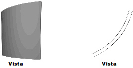
As preferências de paredes curvas incluem os mesmos parâmetros de paredes retas.

Para desenhar paredes curvas:
1. Clique na ferramenta Parede Curva a partir
• Fundamentals: conjunto de ferramentas Paredes.
• Design Series: conjunto de ferramentas Building Shell
2. Clique o Modo de Alinhamento desejado. (veja “Criando Paredes” na página 493).
3. Clique o botão de modo Preferências da Parede (as preferências estão decritas em “Desenhando Paredes Retas” na página 495.)
4.Clique o botão OK quando as preferências da parede curva tiverem sido definidas.
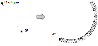
5. Clique no ponto central da Parede Curva.
6. Clique o mouse para começar a desenhar a parede, ou arraste o mouse para desenhar a parede, ou utilize a Barra de Dados para digitar um ângulo específico. Para mais informações dos modos de criação do arco, veja “Criando Arcos” na página 289.
7. Clique o mouse para finalizar a parede.
Clique aqui para uma dica de vídeo sobre este tema (ligação à Internet necessária).
~~~~~~~~~~~~~~~~~~~~~~~~~
O ponto inicial e direção da parede desenhada determinam os lados da parede. O centro da parede é sempre o mesmo, mas o lado esquerdo e direito dependem da direção do desenho. Por exemplo, quando desenhar uma parede em sentido horário, o lado esquerdo é sempre o lado externo; em uma direção anti-horário, ele se torna o interno.
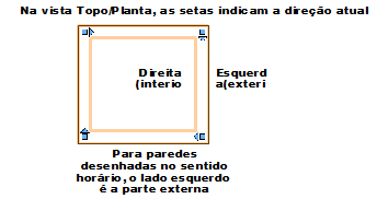
A direção da parede pode ser revertida clicando em Inverter Lados, na paleta Info de Objetos.
~~~~~~~~~~~~~~~~~~~~~~~~~
 Using
Wall Styles
Using
Wall StylesUnstyled walls can be used in the Vectorworks Architect and Landmark products. The attributes of an unstyled wall can be changed from the Attributes palette. The use of wall styles, however, facilitates drawing walls by saving the wall preferences settings so that they can be easily selected as the default style when drawing new walls, or so that they can be applied to existing walls. Wall styles are resources that can be imported into other files and shared as office standards.
A wall style contains a significant amount of information:
• Wall composition and structure (components for standard walls, and frames and panels for curtain walls)
• Insertion options (height constraints, caps, classing)
• Wall attributes (fill, pen, line weight, classing, texture resources (Renderworks required), hatch resources)
• Vertical wall constraints (by layer elevation, layer height or, for the Vectorworks Architect program, story layer levels)
• Component constraints, for standard walls
• Other non-geometric data (wall style name, thermal data, product data, and so on)
Because a wall style contains so much information, it can be time-consuming to create one from scratch. However, a variety of wall styles are provided as default content (default content is automatically imported into the current file at the point of use and displays in the Resource Browser; see “Resource Libraries” na página 215).
Depending on how you use wall styles and which product is in use, usually only one type of wall style, simple or constrained, is needed. Wall styles provided by the Wall or Round Wall tool in a blank file are simple wall styles that use the conventional method of determining the top and bottom wall height according to the layer elevation or layer wall height. However, constrained wall styles are provided in templates named with a BIM prefix; these are available for Vectorworks Architect users from the Use document template list in the Create Document dialog box. These wall styles are constrained to the story level settings in those templates, and they provide additional wall detail, accuracy, and flexibility.
A selected wall can be converted to an unstyled wall by selecting Convert to Unstyled Wall from the Style list in the Object Info palette. The component settings of unstyled walls can be edited by clicking Components from the Object Info palette. When a wall becomes unstyled, it loses all its non-geometric data. An unstyled wall’s properties can be converted into a new wall style with a right-click (Windows) or Ctrl-click (Mac) on the wall; select New Wall Style from Unstyled Wall.
The insertion options of a styled wall (including wall height, constraints, class, and caps) are properties that can be changed from the Object Info palette without requiring a new style definition.
Unused wall styles can be purged; see “Eliminando Objetos Não-Usados” on page 1009.
~~~~~~~~~~~~~~~~~~~~~~~~~
 Creating
Wall Styles
Creating
Wall Styles
To create a straight wall style:

To create a round wall style:
1. Select the Wall or Round Wall tool from the Building Shell tool set, and then click Preferences from the Tool bar.
The Wall Preferences dialog box opens.
2. To modify an existing wall style, select the Wall Style from either the default content or the current file’s content. Alternatively, select Unstyled as the wall style and set the parameters.
3. Specify the wall and component parameters as described in “Criando Paredes” na página 493, and “Desenhando Paredes Retas” na página 495.
The attributes of an unstyled wall can be saved as a wall style. Set the Eyedropper Preferences to pick up all wall attributes and select the Pick Up Sets Defaults option. The Eyedropper tool can then be used to pick up wall attributes from an unstyled wall and add the settings to the Wall Preferences dialog box, where the settings can be saved as a style.
4. Click Save Preferences as Wall Style.
The Assign Name dialog box opens.
5. Enter a unique name for the wall style and click OK.
If the wall style name already exists, you are prompted to cancel and select a different name, or replace existing walls with the wall style applied with the edited wall style. If you are replacing wall styles, the Wall Replacement dialog box opens; specify the wall alignment properties.
6. The new wall style is saved with the file and is listed under Wall Styles in the Resource Browser as well as the Wall Style list in the Tool bar.
A new wall style can also be created by clicking Resources > New Resource > Wall Style in the Resource Browser. A wall style created in this way is not associated with the current wall preference setting, but can be applied later.
7. Worksheets listing the current wall styles and wall areas in the drawing can be added to the drawing from the VA Create Schedule command (in the Architect workspace) or the Resource Browser. From the Resource Browser, open the default architectural reports file from the [Vectorworks]\Libraries folder that is included with the Vectorworks Architect product (see “Resource Libraries” na página 215). Drag the Wall Area and/or Wall Style Report worksheet to the drawing. The worksheet is populated with information from the objects in the current drawing.
~~~~~~~~~~~~~~~~~~~~~~~~~
 Editing
Wall Styles
Editing
Wall Styles
To edit a straight wall style:

To edit a round wall style:
1. Select the wall style from the Resource Browser and click Resources > Edit.
The Edit Wall Style dialog box opens.
2. Edit the wall and component parameters as described in “Criando Paredes” na página 493, and “Desenhando Paredes Retas” na página 495.
If a new wall style Name is specified, it replaces the selected wall style name (similar to selecting Rename from the Resources menu).
3. Click OK.
4. If walls with that style already exist in the drawing, the Wall Replacement dialog box opens.
The wall style to apply cannot be selected (the edited style is applied). Select the wall alignment properties (see “Replacing Wall Styles” na página 505).
5. Click OK to edit the wall style.
Changes apply to any existing walls in the drawing with the edited wall style, and will be used for any subsequent walls created with that wall style.
~~~~~~~~~~~~~~~~~~~~~~~~~
 Applying
Wall Styles
Applying
Wall StylesBy a variety of methods, wall styles can be selected for a wall before drawing it, or applied to existing walls. Once a wall style has been selected for a wall, the Attributes palette is no longer available for changing wall attributes; attributes are set as part of the style.
To apply a wall style prior to drawing the wall:
1. Select the Wall tool or Round Wall tool from the Building Shell tool set.
2. Select the desired style from the Wall Style list on the Tool bar. The available wall styles are from either the default content or the current file’s content.
Alternatively, click Preferences from the Tool bar. In the Wall Preferences dialog box, select the Wall Style.
To apply a wall style from the Resource Browser prior to drawing the wall:
1. Ensure that no walls are selected.
2. Select a wall style in the Resource Browser, and click Resources > Apply.
Alternatively, double-click on the wall style in the Resource Browser.
3. The Wall tool is automatically made active and the selected wall style is applied to the wall as it is drawn. (If a round wall is desired, select the Round Wall tool from the Building Shell tool set.)
To apply a wall style to an existing wall from the Object Info palette:
1. Select one or more walls.
2. From the Object Info palette, select the wall Style from either the default content or the current file’s content; see “Resource Libraries” na página 215.
To apply a different (default) style, select Replace.
To apply a wall style to an existing wall from the Resource Browser:
1. Select one or more walls.
2. Select the wall style from the Resource Browser and click Resources > Apply. Alternatively, drag the selected wall style from the Resource browser to the wall and click on the wall selection.
The Wall Replacement dialog box opens.
3. Select the wall alignment properties. The wall style list is disabled (the style selected in the Resource Browser is applied).
4. Click OK.
A styled wall can be converted to an unstyled wall.
To remove a wall style:
1. Select one or more walls to un-style.
2. From the Object Info palette, select Convert to Unstyled Wall.
The wall is released from its style; its attributes can be edited from the Attributes palette.
~~~~~~~~~~~~~~~~~~~~~~~~~
 Replacing
Wall Styles
Replacing
Wall StylesWall styles applied to existing walls or curtain walls can be replaced with a different wall style.
A wall replacement situation may also occur if pasting a styled wall from another file. You can select a replacement wall style and how to align the styles for the pasted walls.
To replace a wall style:
1. Select one or more walls.
2. From the Object Info palette, select Replace from the Style list.
The Wall Replacement dialog box opens. Specify the new wall style, and then select a component (or the wall) from the current and replacement structure lists. Specify the alignment option for each selection; the preview updates, with a red line showing the replacement alignment.
Click to show/hide the parameters.
If walls with different wall styles were selected for replacement, the current wall preview is blank and components are not listed. Wall alignment can only occur for the left, center, or right of the selected wall(s).
3. Click OK to replace the wall style of the selected wall(s).
Click here for a video tip about this topic (Internet access required).
~~~~~~~~~~~~~~~~~~~~~~~~~
 Creating
Wall End Caps
Creating
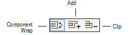
Wall End CapsThe Wall End Cap tool creates both standard and custom component wrapping at the end of a wall. It has three modes:
Mode |
Description |
|---|---|
Component Wrap |
Automatically wraps the selected component, creating a standard wall cap |
Add |
Creates a custom wall end cap by adding |
Clip |
Creates a custom wall end cap by removing |
Preferences |
Sets whether to create wall caps inside or outside the wall endpoint |

To set wall end cap preferences:
1. Click the Wall End Cap tool from the Building Shell tool set.
2. Click Preferences from the Tool bar.
The Wall End Cap Settings dialog box opens.
Determine whether to create the wall end caps outside the wall endpoint. Deselect the option to create the wall end caps inside the wall endpoint, so that the wall length does not extend past the original length.
3. Click OK.
This option is also available from the Object Info palette for existing wall end caps.

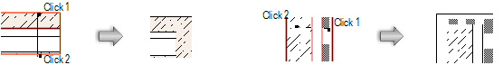
To create a standard end cap by wrapping a component:
1. Click the Wall End Cap tool from the Building Shell tool set.
2. Click Component Wrap from the Tool bar.
3. Click to select a component within the wall. This component wraps along the wall end.
4. Click to select the component where the wrapping should end.
The component wraps around the wall end to the end point.
An End Cap in Wall object is created by the Wall End Cap tool. This object, while distinct from the wall, moves with the wall and adjusts if the wall is resized. The object can be dimensioned, reported in wall schedules, and exported as part of the wall.
The wall cap uses the line weight of the source component, and its 3D geometry is of the same height as the source component.
The Extend Cap Past Wall Endpoint option can be changed from the Object Info palette.

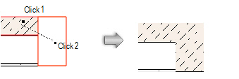
To create a custom wall end cap by adding a shape to a component:
1. Create a 2D, closed shape to represent the wall end cap. The object must intersect the end of the wall.
2. Click the Wall End Cap tool from the Building Shell tool set.
3. Click Add from the Tool bar.
4. Click to select a component within the wall. This component style is used to create the wall end cap.
5. Click to select the shape.
6. The shape is added to the component and the wall end, creating the custom wall cap.

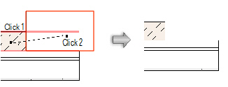
To create a custom end cap by clipping a shape from a component:
1. Create a 2D, closed shape to represent the wall end cap. The object must intersect the end of the wall.
2. Click the Wall End Cap tool from the Building Shell tool set.
3. Click Clip from the Tool bar.
4. Click to select a component within the wall. This component style is used to create the wall end cap.
5. Click to select the shape.
6. The shape is subtracted from the component, creating the custom wall cap.
Click here for a video tip on this topic (Internet connection required).
~~~~~~~~~~~~~~~~~~~~~~~~~
Wall components define the sections that make up a standard wall. For example, to indicate that a wall is made up of studs, inner drywall, outer sheathing, and then a siding material, define a component for each of these items to illustrate their location. Wall components can be offset at the top or the bottom of the wall, individually constrained relative to the wall, the layer, or, for Vectorworks Architect users, to story levels. Components can be textured (Renderworks required), creating realistic section views and rendered views, as well as accurate wall material estimates. The area and volume of wall components can be calculated in worksheets; see “Worksheet Functions” na página 1340).
The overall thickness of a wall is equal to the sum of its components. Component fill and pen style are only displayed in Top/Plan view (except for section viewports in the Vectorworks Design Series products).
Use the Eyedropper tool to copy wall component settings from one wall to another (see “Transferindo Atributos” on page 1093).
Additional wall capabilities are available in the Vectorworks Architect/Landmark product. Curtain walls do not have components.
Wall components can be defined prior to drawing the wall in Wall Preferences mode, or after drawing the wall, from the Object Info palette.
Wall components can also be edited from Wall Preferences mode. Editing a component from wall preferences does not affect existing walls.
Click here for a video tip about this topic (Internet access required).
To define a wall component prior to drawing the wall:
1. Select the Wall tool or Round Wall tool from the appropriate tool set, and then click Preferences from the Tool bar.
• Fundamentals: Walls tool set
• Design Series: Building Shell tool set
The Wall Preferences dialog box opens.
2. On the Definition tab, click New.
The Wall Component Settings dialog box opens. Specify the component thickness, name, and parameters.
Click to show/hide the parameters.
3. Click OK to create the component and return to the Wall Preferences dialog box.
The wall’s Overall Thickness value changes to be determined by its components. As components are defined, they display in the preview. Click and drag a component in the # column to change its order.
4. Click OK.
To define or edit wall components for an existing, unstyled wall:
1. Select the wall(s).
2. From the Object Info palette, click Components.
The Components dialog box opens.
Click to show/hide the parameters.
3. Click New or Edit, and define or edit the components as described previously.
4. Click OK to return to the Components dialog box.
5. Click OK. The new component definition is applied to the selected wall(s).
~~~~~~~~~~~~~~~~~~~~~~~~~
 Hiding
Wall Components
Hiding
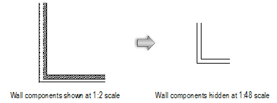
Wall ComponentsThe Hide details preference prevents wall components from being drawn at or below a pre-set layer scale factor, creating a cleaner drawing when printing at small scales. For example, if the scale factor is set to 1:48, components in walls do not display on any layer set to 1/4” or smaller.
To hide wall components:
1. Select File > Document Settings > Document Preferences.
The Document Preferences dialog box opens.
2. Select Hide details when layer scale <= 1:. Enter a scale factor in the scale field.
3. Click OK.
~~~~~~~~~~~~~~~~~~~~~~~~~
 Fitting
Walls to Defined Geometry
Fitting
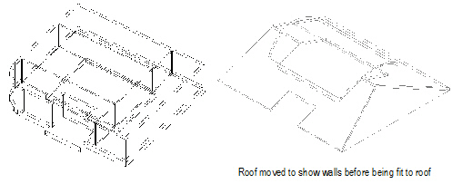
Walls to Defined GeometryIn the Vectorworks Architect and Landmark products, standard walls and curtain walls can be set to the layer height at creation. After creation, they can be automatically extended upward or downward to fit to defining geometry such as the site model, roofs, floors, or NURBS surfaces.
To fit walls to defined geometry:
1. Select the straight or curved wall(s) to be fit.
2. With the wall(s) selected, select the Fit Walls to Objects command from the appropriate menu.
• Architect: AEC > Fit Walls to Objects
• Landmark: Landmark > Architectural > Fit Walls to Objects
The Fit Walls to Objects dialog box opens. Specify the location of the wall object and indicate the fit parameters.
Click to show/hide the parameters.
3. Click OK to fit the wall(s) to the constraining object indicated.
Walls or portions of walls which lie outside the constraining object retain their height as set in the Object Info palette. Walls which have had peaks added (with the Reshape tool) do not have the peaks reset if the peaks lie outside the constraining object. Walls with a bottom fit to the site model retain a level top rather than a fixed height; the top of the wall does not vary with the bottom.
~~~~~~~~~~~~~~~~~~~~~~~~~
For flexibility in the design process, walls can be created automatically based on existing objects in the drawing including spaces, polygons and shapes. Likewise, some object types can be created from walls.
 Creating
Walls from Spaces
Creating
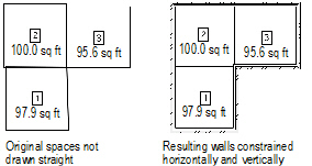
Walls from SpacesOnce the floor plan has been developed with multiple spaces, the interior and exterior walls can be automatically created.
To create walls from spaces:
1. Ensure that space objects are present in the drawing. To automatically create walls with a 3D height, specify a delta-Z value for the design layer where the walls will be created.
2. Select AEC > Space Planning > Create Walls from Spaces.
The Create Walls from Spaces dialog box opens. Specify the style of walls to create and their location.
Click to show/hide the parameters.
The available wall styles are defined by wall style resources (see “Using Wall Styles” na página 502).
3. Click OK to create the walls on the destination layer.
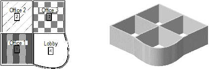
Exterior and interior walls are applied automatically to the spaces. Round walls approximating the curves are used for Bézier and cubic spline vertices in the space objects.
~~~~~~~~~~~~~~~~~~~~~~~~~
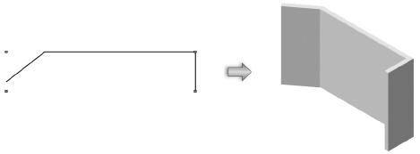
Walls can be created from a polygon.
In the Vectorworks Design Series products, walls can be created by drawing a polyline or shape and then selecting the Create Objects from Shapes command (see “Creating Objects from Shapes” na página 273).
To create walls from a polygon in Vectorworks Fundamentals:
1. Draw or select the polygon to become the basis for the walls.
2. Select Modify > Create Walls from Polygon.
The Create Walls from Poly dialog box opens. Select the desired wall parameters.
Click to show/hide the parameters.
3. Click OK.
The wall(s) are created based on the original polygon and the specified parameters.
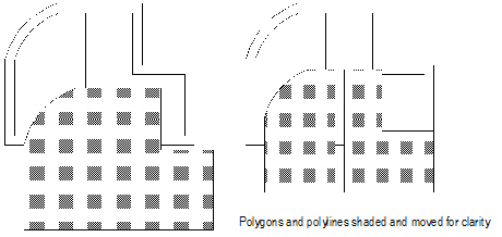
You can create a polygon or polyline based on either the gross area or net area of walls. This is useful for calculating the area of a room, for example, or for using color to differentiate among rooms.
To create a polygon or polyline based on the perimeter of the walls:
1. Select the walls to use for the polygon or polyline. Multiple walls can be selected to create several polygons or polylines at the same time.
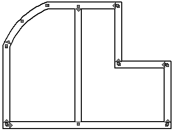
2. Select the Create Polys from Walls command from the appropriate menu:
• Fundamentals: Modify > Create Polys from Walls
• Architect: AEC > Create Polys from Walls
• Landmark: Landmark > Architectural > Create Polys from Walls
• Spotlight: Spotlight > Architectural > Create Polys from Walls
The Create Polys from Walls dialog box opens.
Click to show/hide the parameters.
3. Set the parameters and click OK.
The polygon or polyline is created, leaving the original walls unchanged.
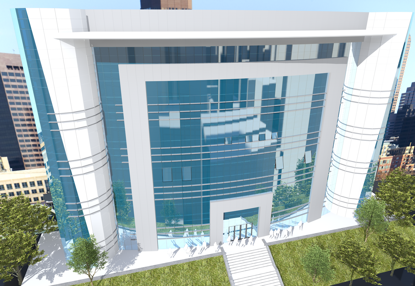
 Creating Curtain Walls
In the Vectorworks Architect and Landmark products, the capabilities of the Wall and Round Wall tools are expanded to create curtain walls. Curtain walls consist of frames that contain panels; often, the panels are made of glass, but they can also be opaque or decorative. The Vectorworks program models the frames, panels, and connections according to real-world architectural standards. Since the curtain wall is based on the Wall tool, it can take advantage of all the benefits of the Wall tool, such as resizing, editing, joining, using walls as the basis of slabs and spaces, bounding by story level, inserting plug-in objects, and more. Doors and windows have special capabilities when they are inserted within curtain walls so that all the design elements work together.

To create straight curtain walls:

To create round curtain walls:
1. Select the Wall or Round Wall tool from the appropriate tool set:
• Fundamentals: Walls tool set
• Design Series: Building Shell tool set
2. Click the desired Offset mode button (see “Criando Paredes” na página 493).
3. To draw with an unstyled wall, select <Unstyled> from the Wall Style list on the Tool bar. If the desired styled wall resource has already been created, select it from the Tool bar list or double-click on the resource in the Resource Browser and proceed to Step 6. Curtain walls have specific wall styles; the default styles begin with the prefix CW for easy identification.
4. Click Preferences from the Tool bar.
The Wall Preferences dialog box opens. This dialog box can be accessed any time afterward to modify default wall settings.
Curtain walls consist of a repeating grid of frames and panels. Specify the number of horizontal and vertical frames that make up one section of the curtain wall, and then specify the appearance of the frames and the panels within that grid. The defined section is repeated over the length and height of the wall.
Curtain walls can be drawn first, and if not using a wall style, the parameters can be set later from the Object Info palette by clicking Curtain Wall Grid. The Curtain Wall Grid dialog box opens, to edit the parameters of the unstyled curtain wall. However, editing unstyled walls by this method may clear existing frames and panels, and recreate the curtain wall grid.
Click to show/hide the parameters.
5. When the curtain wall parameters have been specified, and any changes saved as a wall style resource if desired, click OK. A saved or selected wall style is saved as a resource in the file, and appears in the Resource Browser and in the Wall Style list on the Tool bar.
6. If Polygon mode is selected, click at the starting point of the first curtain wall section.
7. Click to end the first wall section.
To continue creating curtain walls, click at the end of each additional wall section.
8. Double-click to finish the curtain wall if the start point and end point are not at the same location; otherwise, click at the starting location (a SmartCursor cue displays) to finish the wall.
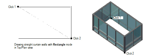
9. Alternatively, if Rectangle mode is selected, click at the wall’s start point; this becomes one corner of the rectangular wall system. Move the mouse to the opposite corner until the desired size is previewed.
10. Click to set a corner point on the wall system. Four walls are created.
~~~~~~~~~~~~~~~~~~~~~~~~~
The frame settings and appearance are controlled individually for each frame location, for maximum flexibility when setting the frame parameters.
Curtain walls can be drawn first, and if not using a wall style, the parameters can be set later from the Object Info palette by clicking Curtain Wall Grid. The Curtain Wall Grid dialog box opens, to edit the parameters of the unstyled curtain wall. However, editing unstyled walls by this method may clear existing frames and panels, and recreate the curtain wall grid.
To set the curtain wall frame appearance:
1. From the Definition tab of the Wall Preferences dialog box, or when editing a curtain wall style, click Frame Settings.
The Frame Settings dialog box opens.
Click to show/hide the parameters.
2. Click OK.
The parameters can be edited from the Object Info palette; see “Wall Properties” na página 531. The Cut Plane parameter determines the height for displaying the curtain wall in Top/Plan view.
~~~~~~~~~~~~~~~~~~~~~~~~~
The panel settings and appearance are specified in the Panel Settings dialog box.
If setting up curtain wall preferences, these parameters are available from the Definition tab of the Wall Preferences dialog box. For an existing curtain wall, they are available from the Curtain Wall Grid dialog box.
To set the curtain wall panel appearance:
1. From the Object Info palette of a selected curtain wall, click Curtain Wall Grid.
The Curtain Wall Grid dialog box opens.
2. Click Panel Settings.
The Panel Settings dialog box opens.
Click to show/hide the parameters.
3. Click OK.
~~~~~~~~~~~~~~~~~~~~~~~~~
 Creating
Wall Features
Creating
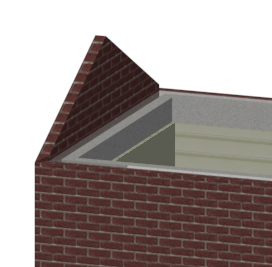
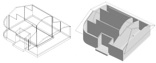
Wall FeaturesOnce a standard round or straight wall has been created, features such as projections and recesses can be added to it. Create wall features from 2D or 3D objects, as well as symbols. By default, 2D objects are extruded to span the height of the wall; offsets from the top and bottom of the wall can be specified as needed. Use 3D objects, such as sweeps or other solids, to create more complicated features. Use symbols to be able to update multiple instances of a feature with a single edit.
It it not recommended to create wall features that are applied to the entire length of the wall, such as battered walls, or wall caps.
Unlike a symbol, a wall feature is actually part of the wall geometry. A wall feature interacts with the wall components, it renders along with the rest of the wall, and if it was created from a 2D object, it automatically adjusts when the wall height changes. Because wall features interact with wall components, wall features cannot be created for curtain walls.
Click here for a video tip about this topic (Internet access required).
~~~~~~~~~~~~~~~~~~~~~~~~~
 Creating
Wall Projections
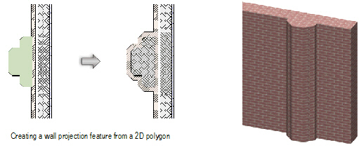
Creating
Wall ProjectionsTo create wall projections:
1. Create the closed 2D or 3D solid object with which to modify the wall. The geometry of the object must define an area or volume that has no self-contacts, no self-intersections, and no edges that fold back on themselves.
2. For a 2D object, simply make sure that the object overlaps the wall, and that the view is Top/Plan. For a 3D object, first create the object at the appropriate height in relation to the bottom of the wall (Z axis); then set the appropriate X and Y axis location so that the object overlaps the wall.
3. With both the wall and the modifier object selected, choose the Create Wall Projection command from the appropriate menu:
• Architect: AEC > Create Wall Projection
• Landmark: Landmark > Architectural > Create Wall Projection
• Spotlight: Spotlight > Architectural > Create Wall Projection
Alternatively, for 2D objects only, select Modify > Add Surface.
The Create Wall Feature Projection dialog box opens; different fields display depending on whether a 2D or 3D modifier object was selected.
Click to show/hide the parameters.
4. Set the parameters and click OK.
~~~~~~~~~~~~~~~~~~~~~~~~~
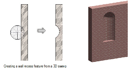
 Creating Wall Recesses
To create a wall recess:
1. Create the closed 2D or 3D solid object with which to modify the wall. The geometry of the object must define an area or volume that has no self-contacts, no self-intersections, and no edges that fold back on themselves.
2. For a 2D object, simply make sure that the object overlaps the wall in Top/Plan view. For a 3D object, first create the object at the appropriate height in relation to the bottom of the wall (Z axis); then set the appropriate X and Y axis location so that the object overlaps the wall.
3. With both the appropriate wall and the modifier object selected, choose the Create Wall Recess command from the appropriate menu:
• Architect: AEC > Create Wall Recess
• Landmark: Landmark > Architectural > Create Wall Recess
• Spotlight: Spotlight > Architectural > Create Wall Recess
Alternatively, for 2D objects only, select Modify > Clip Surface.
The Create Wall Feature Recess dialog box opens; different fields display depending on whether a 2D or 3D modifier object was selected.
Click to show/hide the parameters.
4. Select the options for the wall feature, and click OK.
~~~~~~~~~~~~~~~~~~~~~~~~~
 Wall
Feature Properties
Wall
Feature PropertiesAfter a wall feature has been created, it can be edited in the Object Info palette. Alternatively, right-click (Windows) or Ctrl-click (Mac) on the feature and select Properties from the context menu.
In addition to the parameters available when the feature is created, the following options are available.
Click to show/hide the parameters.
~~~~~~~~~~~~~~~~~~~~~~~~~
 Editing
Wall Features
Editing
Wall FeaturesSimilar to symbols, the original 2D or 3D object (or symbol) can be edited after the wall feature is created. For example, the location or shape of the object can be changed.
To access the editing mode, double-click the wall feature. Alternatively, right-click (Windows) or Ctrl-click (Mac) on the feature and select Edit from the context menu. To delete the wall feature, delete the original object from which the wall feature was created. Click Exit Wall Feature to exit the editing mode.
Also similar to symbols, wall features can be moved and duplicated in various ways in both straight and round walls. See the following topics:
• “Moving Symbols in Walls with the Selection Tool” on page 252
• “Nudging Symbols in Walls” on page 253
• “Moving Symbols in Walls with the Move Command” on page 253
• “Moving Symbols in Walls with the Move by Points Tool” on page 254
• “Duplicando em Matrizes” on page 1012
~~~~~~~~~~~~~~~~~~~~~~~~~