Creating
Landscape WallsCreating
Landscape Walls
Creating
Landscape WallsCreating
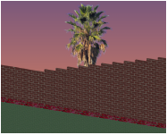
Landscape WallsThe Vectorworks Architect and Landmark products include the ability to create a stepped wall. The Vectorworks Landmark program also contains the ability to create a retaining wall site modifier. The stepped wall and retaining wall site modifier are based on walls created with the Wall or Round Wall tool, offering the benefits and flexibility of the architectural wall tools.
~~~~~~~~~~~~~~~~~~~~~~~~~
 Creating Stepped
Walls
Creating Stepped
WallsCommand |
Workspace: Path |
|---|---|
Create Stepped Wall |
• Architect: AEC • Landmark: Landmark > Architectural |
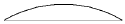
Stepped walls add wall peaks to existing walls created with the Wall tool or Round Wall tool. The existing wall can be a single wall or a chain of multiple wall segments that are L-joined to each other. Stepped walls can have a constant rise at each interval, or conform to underlying terrain with a variable rise, such as free-standing landscape walls or fences.
To create a stepped wall:
1 Select the wall or multiple, L-joined walls.
2 Select the command.
The Create Stepped Wall dialog box opens. Set the stair parameters.
The options available depend on the selected Step Style (even steps or terrain steps). If the parameters are set so that the steps are uneven, the top step is truncated.

► Clique para exibir/ocultar parâmetros.
The Send to Surface command can be used on walls; it sets the bottom Z value at the start of the wall to the existing terrain surface (see Sending Objects to the Site Model Surface).
~~~~~~~~~~~~~~~~~~~~~~~~~
 Creating Retaining
Walls
Creating Retaining
WallsCommand |
Workspace: Path |
|---|---|
Create Retaining Wall Site Modifier |
• Architect: AEC > Terrain • Landmark: Landmark |
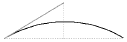
A retaining wall site modifier can be created based on existing walls created with the Wall tool or Round Wall tool. The existing wall can be a single wall or a chain of multiple wall segments that are L-joined to each other. The retaining wall created can modify the site model, and the terrain can be sculpted around the retaining wall.
Once created, the retaining wall site modifier is not associated with the wall object used to create it.
To create a retaining wall site modifier:
1 Select the wall or multiple, L-joined walls.
While walls are typically used as the basis for creating a retaining wall, other valid selections include a hardscape object or an extrude object.
2 Select the command.
The Create Retaining Wall Site Modifier dialog box opens. Set the initial location of the site modifiers within the retaining wall. There are three distinct areas that can modify the site model:
• The pad at the bottom of the wall, which can be offset from the top or bottom of the wall, or simply follow the terrain
• The left and right side edges of the wall, which can be offset from the top or bottom of the wall, or follow the terrain
• The starting and ending edges of the wall
The left and right sides of the wall are determined by the wall direction as it was drawn.
► Clique para exibir/ocultar parâmetros.
The original wall remains in the drawing; the retaining wall site modifier is a new, separate object.
3 Update the site model to apply the changes (select the site model and click Update from the Object Info palette).

Retaining wall parameters can be edited from the Object Info palette.
► Clique para exibir/ocultar parâmetros.
The retaining wall site modifier consists of four modifier edges, joined by common vertices. The left and right edges of the retaining wall site modifier can be reshaped with the Reshape tool, similar to reshaping walls (see Reshaping Walls). Move vertices, and add or delete vertices to reshape the retaining wall.

The start and end edges cannot be directly edited with the Reshape tool. However, a vertex added to the left or right edge can be edited by the Reshape tool (select Start/End Modifier Edge from the Move list in the Object Info palette, and click Add Vertex). Adding vertices to the start and end edges allows them to be reshaped.

The Send to Surface command can be used to send either the retaining wall modifier edge or the pad to the surface of the site model.
~~~~~~~~~~~~~~~~~~~~~~~~~
 Creating
Hardscape Objects
Creating
Hardscape ObjectsMode |
Tool |
Tool set |
|---|---|---|
Modes for the Polyline Tool |
Hardscape
|
Site Planning |
A hardscape object consists of paved areas with joint patterns and optional borders. A boundary hardscape or pathway hardscape can be created. To draw a hardscape object, either use the Hardscape tool, or create a polyline and then select the Create Objects from Shapes command (see Creating Objects from Shapes). The hardscape object can modify the site model.
The following modes are available.

Mode |
Description |
|---|---|
Hardscape |
Opens the Resource Selector to select a resource for placement; double-click a resource to activate it |
Boundary Configuration |
Creates a hardscape with a boundary configuration, defining an area with an optional border |
Pathway Configuration |
Creates a hardscape along a path |
Pathway Edge options |
For the pathway configuration, sets where to create the pathway in relation to the drawn polyline |
Polyline creation options |
Selects the method for drawing the polyline upon which the hardscape object is based; see Creating Polylines |
Preferences |
Sets the default preferences for the hardscape object |
To create a hardscape object:
1 Click the tool and mode.
2 Do one of the following:
• To use an existing hardscape from the resource libraries, click Hardscape on the Tool bar. From the Resource Selector, double-click a resource to activate it.
• To create a custom hardscape, click Preferences. From the Hardscape Object Settings dialog box, set the default properties. The properties can be edited from the Object Info palette.
► Clique para exibir/ocultar parâmetros.
The Stipple joint patterns are a processor-intensive action for large hardscape objects and can significantly increase regeneration time.
When drawing a hardscape object with a curved boundary, speed the regeneration time by setting the 2D conversion resolution in Vectorworks preferences to low (see Aba Edição).
3 Click the appropriate mode in the Tool bar to specify the creation method of the hardscape object. Select whether to create a boundary or pathway hardscape object.
The hardscape configuration can also be changed after creation from either the Hardscape Object Settings dialog box or the hardscape context menu commands (see Converting the Hardscape Object to a Boundary or Pathway Configuration).
4 Click to set the hardscape object’s start point.
5 Click to set the end of the segment and the beginning of the next. Continue drawing segments in this manner until the hardscape object is complete. Return to the start point (for boundary configurations), or simply double-click (for either pathway or boundary configurations) to finish creating the hardscape object.
6 When classing the subcomponents of the hardscape object, such as the joints or tags, the class visibility of the specified class controls the visibility of the corresponding subcomponent. The class attributes are only applied to the corresponding subcomponent when the Use at Creation option is selected for the class. For example, if the Joint Class is set to the Site-Hardscape Comp-Main Joint class, and that class specifies a hatch Fill Style, edit the class and select the Use at Creation option to apply the fill attribute.
7 If the hardscape 3D Type is set to Pad Modifier or Texture Bed Modifier, update the site model to apply the modification. Select the site model and click Update from the Object Info palette.
8 If the hardscape is set to slope, specify the slope properties in the Object Info palette, and/or adjust slope indicator control points and reshape the corners in a 3D view (see Editing the Hardscape Object Settings).
|
Click here and here for video tips about this topic (internet access required). |
To edit the hardscape object path in object editing mode, select the hardscape and select Modify > Edit Hardscape.
~~~~~~~~~~~~~~~~~~~~~~~~~
 Concept:
Hardscape Fills and Joint Patterns
Concept:
Hardscape Fills and Joint PatternsA single hardscape object can have multiple components, each with its own fill or joint pattern.
The hardscape can be filled with a solid color, pattern, hatch, tile, gradient, or image from the Attributes palette. See Fill Attributes for details.
For the main and border hardscape areas, different joint patterns are available.
• Main joint patterns include flagstones and pavers, as well as hatches, stipples, and tiles that are applied independent of the Attributes palette.
• Border joint patterns include spaced joints and the same hatch, stipple, and tile options available for main joint patterns.
If a main joint pattern is specified, it is drawn over the hardscape object fill. Both the object fill and the main joint pattern apply to the entire hardscape, unless it has a border.
~~~~~~~~~~~~~~~~~~~~~~~~~
 Specifying
Hardscape Joint Patterns
Specifying
Hardscape Joint PatternsThe Vectorworks Landmark program offers a variety of joint pattern options from the Hardscape Object Settings dialog box (see Creating Hardscape Objects). Available options depend on which component of the hardscape is selected.
Hatch, stipple, and tile joint patterns are available for both the main and border hardscape areas.
1 To specify a hatch, stipple, or tile joint pattern, select the resource type from the Joint Pattern list.
The Choose Fill dialog box opens.
2 Click Pick a Resource to open the Resource Selector; double-click a resource to activate it.
The selected resource’s name displays beneath the Joint Pattern list.

If Flagstone, Pavers-Grid, or Pavers-Running is selected for the main joint pattern, the Set Joint Pattern Options dialog box opens. Set the parameters.
► Clique para exibir/ocultar parâmetros.

If Pavers-Radial is selected for the main joint pattern (Boundary Configuration required), the Set Radial Pattern Options dialog box opens. Set the parameters.
Radial pavers can be used with any shape hardscape that has a Boundary Configuration. The hardscape boundary clips the circular pattern to fit.
► Clique para exibir/ocultar parâmetros.

If Pavers-Curved Path is selected for the main joint pattern (Pathway Configuration required), the Set Curved Path Pattern Options dialog box opens. Set the parameters.
► Clique para exibir/ocultar parâmetros.

If Spaced Joints is selected for the border joint pattern, the Enter Value dialog box opens. Enter the desired joint spacing value.

~~~~~~~~~~~~~~~~~~~~~~~~~
 Editing
Hardscape Fills and Joint Patterns
Editing
Hardscape Fills and Joint PatternsHardscape fills and joint patterns can be modified directly in the drawing.
Tool |
Tool set |
|---|---|
Attribute Mapping
|
• Basic • Visualization |
The Attribute Mapping tool maps tile, associative hatch, gradient, and image fills, as well as hardscape joint patterns.
To interactively map a hardscape fill or joint pattern:
1 In Top/Plan view, select a hardscape object with a specified fill or joint pattern.
2 Click the tool.
3 From the Selected Component list on the Tool bar, select which hardscape component to edit: the Object Fill, Main Joint Pattern, or Border Joint Pattern.
4 An editing object is placed over the selected component. The origin of the component fill or joint pattern is at the corner of the editing object where the red and green lines meet.
5 Use the editing object to move, scale, and rotate the selected fill or joint pattern. The fill or joint pattern can also be nudged. For more information on using the Attribute Mapping tool, see Mapping Fills with the Attribute Mapping Tool.
Alternatively, you can move a joint pattern by moving the control point at the joint pattern origin, as described in the next section.
If Spaced Joints is specified for the border joint pattern, the Attribute Mapping tool can be used to move and scale the pattern; spaced joints cannot be rotated.
While the Attribute Mapping tool is the recommended method of editing joint patterns, the joint pattern origin can also be moved with the Selection tool. The joint pattern origin has a control point marked with a locus for identification: a red locus for the main joint pattern, and a green locus for the border joint pattern.
If Spaced Joints is specified for the border joint pattern, no locus or control point display.
To move the origin of a hardscape joint pattern:
In Top/Plan view, select the control point at the joint pattern origin and drag it to the desired location.
Individual hardscape objects can be joined to create more complex hardscapes whose fills and joint patterns align.
When joining boundary hardscapes with similar fill types, use the Add Surface command; see Adicionar Superfície.
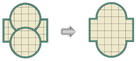
To coordinate the joint patterns of several hardscape objects, configure the hardscape objects with the same settings and drag the origin points of their main joint patterns (marked with red loci) to a common location.

~~~~~~~~~~~~~~~~~~~~~~~~~
 Editing
the Hardscape Object Settings
Editing
the Hardscape Object SettingsThe parameters can be edited for selected hardscape objects through the Hardscape Settings button on the Shape tab of the Object Info palette. To modify the default hardscape object settings, click Preferences on the Tool bar.
Many of the parameters are identical to those used to create the hardscape object (see Creating Hardscape Objects). However, certain parameters are accessible from the Object Info palette only.
If the hardscape is set to slope, specify the slope properties in the Object Info palette and/or by adjusting slope indicator control points and reshaping the hardscape corners in a 3D view.
• Select the method of defining the slope from the Slope Def list in the Object Info palette, and specify the slope parameters. The slope parameters do not display for a Slope Def of None. As values are entered in the Object Info palette, the other parameters are automatically calculated and displayed.
• A banked slope can be contoured. The reference elevation control point indicates the start elevation of the hardscape, and the dashed line that passes through the reference elevation control point represents a constant elevation along the line. The dashed line indicates and controls the Contour Angle in the Object Info palette; it is only visible when the hardscape is selected with the Selection tool, and it does not print. All the points on the line are at the same elevation; move the contour angle control points to define how the hardscape is banked along the hardscape slope. The contour angle must always be between 1 and 90 degrees of the slope vector (the banked contour cannot be parallel or perpendicular to the hardscape slope).
• In addition to the hardscape slope, up to two custom slope axes can be specified: Slope A and Slope B. Slope arrows can be displayed on the hardscape to indicate the slope angles of the main slope and the two custom axes; select Show Slope, Show Slope A, and/or Show Slope B. The slope arrows are interactive; move a control point to adjust the slope direction, and the slope at that location is displayed. The control points of the slope arrows are only visible when the hardscape is selected with the Selection tool, and they do not print.
• The Object Info palette displays the Elevation at End so that hardscapes that meet at the bottom of a slope can be set to the same ending elevation. The planes for two hardscapes match when their contour lines are parallel, and the starting point of one hardscape is on the plane of the other hardscape.
• In Top/Plan view, select the control points of the slope arrows or the contour angle indicator, to interactively display the slope at that location. Changes to the slope values in the Object Info palette affect all the slope parameters. To set the slope plane, change the slope and the contour angle, or change slope A and slope B.
• In Top/Plan view, the Reshape tool changes the shape of the hardscape. If the hardscape is set to slope, use the Reshape tool in a 3D view to adjust the elevation at the corners of the hardscape.
► Clique para exibir/ocultar parâmetros.
To set individual border segments to invisible for boundary hardscapes or cut-out holes, select the hardscape object, and then click the Reshape tool. Click Hide or Show Edges mode. Click the midpoint of the hardscape border segments or the cut-out hole to hide. Repeat this process to set the border segments back to visible, if necessary.
To quickly determine the left and right side of a pathway hardscape object, select the hardscape object and click the middle button next to the Vertex field on the Shape tab of the Object Info palette; while the button is clicked, the first vertex of the hardscape object is highlighted with a red box.
When classing the subcomponents of the hardscape object, such as for the joints or tags, the class visibility of the specified class controls the visibility of the corresponding subcomponent. The class attributes are only applied to the corresponding subcomponent when the Use at Creation option is selected for the class. For example, if the Joint Class is set to the Hardscape - Component - Main Joint class, and that class specifies a hatch Fill Style, edit the class and select the Use at Creation option to apply the fill attribute. See Setting Class Attributes.
A hardscape object can be used as the basis of a retaining wall. This provides the ability to sculpt the site model around the hardscape. See Creating Retaining Walls.
Double-click the hardscape object to activate the Reshape tool, or select the Reshape tool from the Basic palette. Select the object handles to reshape the hardscape object. For more information, see Remodelando Objetos.
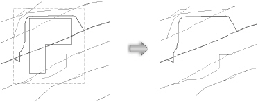
After creation, a boundary hardscape object can be converted to a pathway hardscape object, and similarly, a pathway configuration can be converted to a boundary configuration. The conversion preserves the appearance, but the path of the object changes.

To convert a boundary hardscape object to a pathway hardscape configuration:
1 Select the boundary hardscape object.
2 Right-click on the hardscape object and select Convert to Pathway from the context menu.
To convert a pathway hardscape object to a boundary hardscape configuration:
1 Select the pathway hardscape object.
2 Right-click on the hardscape object and select Convert to Boundary from the context menu.
Alternatively, click Hardscape Settings from the Object Info palette of a selected hardscape object, and select the configuration.
Hardscape tags can be adjusted in several ways.
• When hardscape tags are required, their default appearance is normally specified in the hardscape object settings.
• Individual hardscape tags can then be changed for selected hardscape objects by adjusting the hardscape tag parameters from the Object Info palette.
• The hardscape tag class controls the appearance of the leader/shoulder lines, as well as the marker style.
• To align hardscape tags for improved readability, use the Align/Distribute Leader Lines command (see Aligning and Distributing Leader Lines).
• If an individual tag needs to be repositioned, hardscape tags also have two control points for adjusting the shoulder length, tag shoulder angle, and tag location; or the shoulder location, leader line length, and tag approach angle.

Once the hardscape object is set to the desired appearance, you can save the settings for future use or for import into other files.
To save the selected hardscape object settings:
1 Select a hardscape object.
2 From the Object Info palette, click Save Hardscape.
The Name Hardscape Symbol dialog box opens.
3 Enter a unique name.
The hardscape settings are saved as a resource in the “Hardscapes” symbol folder in the active file. Boundary and pathway hardscape objects are assigned unique thumbnail view icons for easy identification. See Resource Manager.
4 To use a saved hardscape object, do one of the following:
• To draw a hardscape with the Hardscape tool, click Hardscape on the Tool bar. From the Resource Selector, double-click a resource to activate it.
• To apply saved settings to an existing hardscape, from the Resource Manager, right-click on the resource, and select Apply from the context menu. Alternatively, double-click on the resource or drag the resource onto an object to apply it.
~~~~~~~~~~~~~~~~~~~~~~~~~
 Showing
and Hiding Site Modifiers
Showing
and Hiding Site ModifiersCommand |
Path |
|---|---|
Show or Hide Site Modifiers |
View > Show |
In the Vectorworks Landmark product, site modifiers such as pads, grade limits, and portions of roads and retaining walls can be made hidden or visible. The modifications to the proposed site model are still visible even when the modifier is hidden.
To show or hide site model modifiers:
1 Select the command.
2 If site modifiers were hidden, they are displayed; if they were visible, they become hidden.
 Correcting
Site Modifier Conflicts
Correcting
Site Modifier ConflictsIf site modifier conflicts are detected when the site model is updated, an icon displays at the location of each issue.
The following modifier problems can generate conflicts:
• Pad which does not lie inside the grade limits
• Pad intersecting grade limits or the site border
• Two intersecting pads
• Spoil pile intersecting the site border
• Spoil pile intersecting grade limits or the site border
• Two intersecting spoil piles
• Texture bed intersecting the site border
• Two intersecting texture beds
• Locus which does not lie inside the grade limits
If these conflicts exist, the site model can still be generated and modified; however, results may not be as expected. It may be better to resolve the conflicts and update the site model again before proceeding.
When the site model object is selected, the Object Info palette’s Modifier Conflict Count field displays the number of conflicts, and an icon displays at the location of each conflict. Hold the cursor over an icon to display a SmartCursor cue that describes the conflict. Resolve the conflicts by making adjustments to prevent all intersecting modifiers.
![]()
To hide the icons from view (but not resolve the underlying conflicts), deselect Show Modifier Conflicts from the Object Info palette.
Update the site model to ensure that all conflicts have been resolved.
~~~~~~~~~~~~~~~~~~~~~~~~~
 Creating
Property Lines
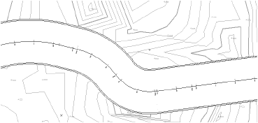
Creating
Property LinesUse the Property Line tool to draw property lines. Alternatively, use one of the following methods.
• Draw a polyline and then select the Create Objects from Shapes command (see Creating Objects from Shapes).
• Draw arcs and lines, select Modify > Compose to create a single polyline, and then select the Create Objects from Shapes command.
|
Click here for a video tip about this topic (internet access required). |

The Property Line tool is in the Site Planning tool set.
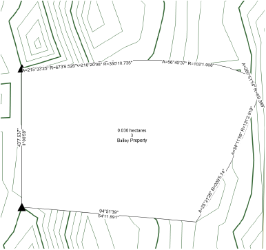
The Property Line tool interactively creates property boundaries from survey data. The resulting polyline is composed of line and/or arc segments. The closing segment can be automatically drawn and measured; each segment can be individually labeled with distance and bearing. Preformatted schedules provide information about property line segments and curves.
The following modes are available.

Mode |
Description |
|---|---|
Bearing and Distance |
Draws a property line by sequentially specifying the bearing and distance of each linear or curved segment of the line |
Polyline |
Draws a property line using the selected polyline creation options and the current preference settings (see Property Line Parameters) |
Polyline creation options |
For Polyline mode, selects the method for drawing the polyline upon which the object is based; see Creating Polylines |
Preferences |
Opens the object properties dialog box to set the default preferences for property lines |
~~~~~~~~~~~~~~~~~~~~~~~~~
 Creating
Property Lines with Bearing and Distance Data
Creating
Property Lines with Bearing and Distance DataMode |
Tool |
Tool set |
|---|---|---|
Bearing and Distance |
Property Line
|
Site Planning |
To create property lines using the bearing and distance of each line segment:
1 Click the tool and mode.
2 Click to set the starting point of the first property line segment.
A red bull’s-eye is placed on the drawing to mark the starting point; the Define Property Line dialog box opens.
3 Specify the segment parameters and click Add to update the drawing file. Continue to add or remove segments as needed.
Alternatively, for simpler, linear-only entry, click Preferences. From the object properties dialog box, click Simple Dialog on Bearing and Distance Mode. Now when you click to place the starting point, the Create Property Line dialog box opens. Enter the Azimuth and Distance for each segment, and select whether to close the shape automatically with the final selection.
► Clique para exibir/ocultar parâmetros.
If this is the first time the Property Line tool has been used, the object properties dialog box opens. Set the defaults (see Property Line Parameters).
~~~~~~~~~~~~~~~~~~~~~~~~~
 Drawing Property Lines Manually
Mode |
Tool |
Tool set |
|---|---|---|
Modes for the Polyline Tool |
Property Line
|
Site Planning |
To create property lines by drawing a polyline:
1 Click the tool and mode.
2 Click to set the starting point of the first property line segment.
For information on using the polyline creation options, see Creating Polylines.
3 Click to set the end of the segment and the beginning of the next. Continue drawing segments in this manner until the property line is complete. Return to the start point or simply double-click to finish creating the property line.
If you use non-arc vertices, the curve segments are approximated into arc segments.
If this is the first time the Property Line tool has been used, the object properties dialog box opens. Set the defaults (see Property Line Parameters).
~~~~~~~~~~~~~~~~~~~~~~~~~
 Property
Line Parameters
Property
Line ParametersProperty line preferences can be set before the property line object is inserted in the drawing in the object properties dialog box; access it by clicking the Property Line tool and then clicking the Preferences button from the Tool bar. These preferences serve as the new default for property lines inserted in the drawing until the preferences are changed.
Parameters can be edited for selected property line objects after placement, in the Object Info palette.
Edit the shape of selected property lines by using the Reshape tool, or by clicking the Edit with Dialog button from the Object Info palette. See Remodelando Objetos for information on using the Reshape tool for editing.
► Clique para exibir/ocultar parâmetros.
If the property line is designated to be a texture bed on the site model, select Tools > Organization. On the Classes tab, select the class designated as the texture bed class, and assign it a distinctive fill color or a texture. Select the site model and click Update from the Object Info palette; the property line displays as a texture bed on the site model. Switch to a 3D view and render for the full effect.
~~~~~~~~~~~~~~~~~~~~~~~~~
 Creating
Railings and Fences
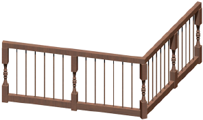
Creating
Railings and FencesMode |
Tool |
Workspace: Tool set |
|---|---|---|
Modes for the Polyline Tool |
Railing/Fence
|
• Landmark: Site Planning or Furn/Fixtures • Architect: Furn/Fixtures |
Use the Railing/Fence tool to create a railing or fence along a specified path using standard polyline creation modes. You can also use this tool to create railings and fences along a single, straight 3D line at any angle.
Alternatively, create a polyline and then select the Create Objects from Shapes command (see Creating Objects from Shapes).

Mode |
Description |
|---|---|
Polyline |
Draws a railing or fence along a path using the selected polyline creation options and the current preference settings; the object will be placed on the layer plane |
3D Line |
Draws a railing or fence along a line at any angle; snap the line to a site model object to follow the contours of hilly areas, for example |
Polyline creation options |
When Polyline mode is selected, selects the method for drawing the polyline upon which the railing or fence is based; see Creating Polylines |
Preferences |
Opens the Railing/Fence Settings dialog box, to set default parameters |
Symbol Selection list |
Select a symbol from the list to use for the fence or railing object when it is created; or select Current Settings to use the settings in the Railing/Fence Settings dialog box |
To create a railing or fence:
1 Click the tool and mode.
2 Click the drawing mode from the Tool bar:
• To draw the object along a polyline path, click Polyline, and then click the polyline option to use.
• To draw the object along a single, straight 3D line at any angle, click 3D Line.
3 Do one of the following:
• To use an existing fence symbol, select it from the Symbol Selection list on the Tool bar.
• To create a custom fence symbol, click Preferences. The Railing/Fence Settings dialog box opens. Set the default properties for this session.
4 In 3D Line mode, click to set the start point, and click again to set the end point of the object.
In Polyline mode, click to set the start point; each subsequent click ends the current segment and begins the next. To complete the object, click the start point again (for a closed object), or double-click (for an open object).
|
Click here for a video tip about this topic (internet access required). |
To edit the parameters for an existing railing or fence, select the object and click Settings from the Object Info palette. Alternatively, right-click the object and select Properties from the context menu.
You can reshape a railing or fence that was drawn in Polyline mode. In Top/Plan view, double-click the object to activate the Reshape tool, or click the Reshape tool from the Basic palette. Drag the object handles to reshape the object, or add or delete vertices as described in Remodelando Objetos.
~~~~~~~~~~~~~~~~~~~~~~~~~
 Railing and Fence Settings
The settings are grouped into several panes of related parameters. Select each group of parameters from the list in the left pane of the dialog box; the parameters display in the center pane. The right pane of the dialog box always displays a preview of the object based on the current settings.
► Clique para exibir/ocultar parâmetros.
► Clique para exibir/ocultar parâmetros.
If you select a different symbol after making parameter changes on any tab, the New Railing dialog box opens. Each railing or fence symbol has default settings. If you switch to a new symbol, you can either use the default settings, or transfer the current settings to the new object. From the dialog box, select specific settings to transfer, or click All or None to select or deselect all the settings.
► Clique para exibir/ocultar parâmetros.
► Clique para exibir/ocultar parâmetros.
► Clique para exibir/ocultar parâmetros.
For Top/Plan view, enter an angle for chamfers at each end of the railing or fence; enter 0 (zero) for a straight edge.
The class and class graphic attributes of each part of the railing or fence display. Double-click an item to open an attributes dialog box. See The Attributes Palette for information about setting attributes.
You can save the railing or fence configuration as a symbol in the current file or in a library file. The object is saved as a red symbol and becomes a plug-in object with pre-set parameters when inserted. See Símbolos.
To save a railing or fence as a symbol:
1 From the Railing/Fence Settings dialog box, open the General pane, and click Save as Symbol.
The Save Railing/Fence dialog box opens.
► Clique para exibir/ocultar parâmetros.
2 Select the destination file for the symbol.
• To save the symbol in a library file, select Save as template in library file and enter a name for the symbol. It will be available from the Symbol Selection list in the General pane, under the Custom Defaults category. Library files can be shared among users.
• To save the symbol in the current file, select Save as symbol in current document, enter a name for the symbol, and select a folder destination for the symbol. It will be available from the Symbol Selection list in the General pane, under the Current document category, and also from the Resource Manager. Symbols can be shared by exporting them from the Resource Manager (see Exporting Resources).
~~~~~~~~~~~~~~~~~~~~~~~~~
 Analyzing
the Site Model
Analyzing
the Site ModelCommand |
Workspace: Path |
|---|---|
Create Site Volume List |
• Architect: AEC > Terrain • Landmark: Landmark |
The individual cut and fill calculations for a site model can be listed in a report for verification.
To list site model volume:
1 Select the site model to analyze. Only one site model can be analyzed at a time.
2 Select the command.
The Create Site Model Volume List dialog box opens. On the Columns tab, select the columns of site model data to include in the report.
► Clique para exibir/ocultar parâmetros.
3 On the Grade Limits Modifiers tab, select the grade limits site modifiers to include in the report calculations.
► Clique para exibir/ocultar parâmetros.
4 On the Options tab, choose report output parameters.
► Clique para exibir/ocultar parâmetros.
 Zone of
Visual Influence Analysis
Zone of
Visual Influence AnalysisCommand |
Workspace: Path |
|---|---|
Zone of Visual Influence |
• Designer: AEC > Terrain • Landmark: Landmark |
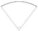
This type of analysis creates a representation of shadowed and lighted areas as seen from a specified point of view.
To perform a zone of visual influence analysis:
1 Select the site model to analyze.
2 Select the command.
The Zone of Visual Influence dialog box opens. Specify the analysis parameters.
► Clique para exibir/ocultar parâmetros.
3 Click the site model to indicate the observation point.
4 Click again to perform the analysis.
A light source is automatically inserted, and the layer is rendered to complete the analysis. Dark regions indicate areas that cannot be seen from the specified observation point at that viewing level.

~~~~~~~~~~~~~~~~~~~~~~~~~
 Obtaining
Site Model Data
Obtaining
Site Model DataCommand |
Workspace: Path |
|---|---|
Site Modifier Section |
• Architect: AEC > Terrain • Landmark: Landmark |
The Site Model Section command creates a profile or sectional view of the site.
To create a site model section:
1 Draw or select a 2D polygon or polyline to define the section alignment. In the Vectorworks Landmark product, if you are selecting a previously drawn polyline with station points (such as a road or Roadway (Poly) object), a station point profile can be created.
The polygon or polyline vertices must be contained within the limits of the site model.
2 With the polygon or polyline selected, select the command.
The Create Site Model Section dialog box opens. Specify the site model section parameters.
► Clique para exibir/ocultar parâmetros.
The Site Model Section Formatting dialog box opens. Specify the formatting for the site model section graphic.
► Clique para exibir/ocultar parâmetros.
4 Click OK to return to the Create Site Model Section dialog box.
5 Click OK to create the sectional view of the site. If the site model changes, the site model section needs to be recreated.

~~~~~~~~~~~~~~~~~~~~~~~~~
 Calculating
Grade for a Site Model
Calculating
Grade for a Site ModelThe Grade tool is available in all Vectorworks Design Series products, but its site model functionality requires additional features that are available only in the Landmark product. For information on creating solid sections from grade objects, see Creating a Solid Section from Grade Objects.

The Grade tool is in the Site Planning tool set (Designer and Landmark workspaces) and the Building Shell tool set (Architect and Spotlight workspaces).
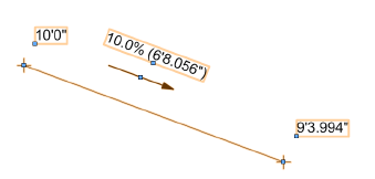
When used for site planning, the Grade tool annotates terrain slopes on site plan documents.
Networks of grade objects can be created to show slope characteristics across a surface. Grade objects can be used in conjunction with a site model, and can modify the site model. In addition, 3D loci can be generated from grade object elevations, and used as the basis of creating a site model.
The Grade tool has three modes:

Mode |
Description |
|---|---|
Insert |
Draws a grade object based on set elevation parameters or a site model |
Edit Elevation |
Changes the elevation value of one or more existing grade objects |
Update |
Updates all grade objects in the drawing, applying current preference settings and updating any overlapped elevation points |
Preferences |
Sets the default global preferences for the grade object |
~~~~~~~~~~~~~~~~~~~~~~~~~
 Specifying
Global Grade Object Preferences
Specifying
Global Grade Object PreferencesTool |
Workspace: Tool set |
|---|---|
Grade
|
• Designer and Landmark: Site Planning • Architect and Spotlight: Building Shell |
The grade indicator appearance for all grade objects in the file can be specified globally.
To set global grade object appearance:
1 Click the tool.
2 Click Preferences. Alternatively, select an existing grade object; click Settings from the Object Info palette, double-click the grade object, or right-click on a grade object and select Edit from the context menu.
The Grade Settings dialog box opens. Click the Global Settings tab and enter the desired settings.
► Clique para exibir/ocultar parâmetros.
3 Click Update from the Tool bar to update all grade objects in the drawing with the global settings.
~~~~~~~~~~~~~~~~~~~~~~~~~
 Inserting
Grade Objects
Inserting
Grade ObjectsMode |
Tool |
Workspace: Tool set |
|---|---|---|
Insert |
Grade
|
• Designer and Landmark: Site Planning • Architect and Spotlight: Building Shell |
To insert a grade object:
1 Click the tool and mode.
2 Click to set the start of the grade. Move the cursor and click again to set the end point.
The Grade Settings dialog box opens. Click the Object Properties tab and enter the desired settings.
► Clique para exibir/ocultar parâmetros.
Grade objects can be edited from the Object Info palette. Commonly-required parameters can be accessed directly from the Object Info palette, or click Settings to change any of the parameters of selected grade objects. Alternatively, edit the settings of a grade object by double-clicking on it, or right-click on a grade object and select Edit from the context menu.
Grade objects can be used together, using an existing grade object as a reference for another grade object. Either move the endpoint of one grade object onto the line of another grade object, or create a new grade object with an end point on an existing grade object. The existing grade object is split at the new endpoint, creating a network of overlapping grade objects. The elevation of the shared point is interpolated from the slope of the existing object; if an elevation point is updated, all overlapping grade objects automatically update. Click Update mode from the Tool bar of the Grade tool to force an update of all overlapping grade objects.

|
Click here for a video tip about this topic (internet access required). |
~~~~~~~~~~~~~~~~~~~~~~~~~
 Editing Elevation
Mode |
Tool |
Workspace: Tool set |
|---|---|---|
Edit Elevation |
Grade
|
• Designer and Landmark: Site Planning • Architect and Spotlight: Building Shell |
If the elevation changes after one or more grade objects have been placed, there is no need to replace the existing grade objects. Change the elevation of one end of a grade object, or offset the elevation of selected (or all) grade objects in the drawing.
Elevation marker symbols must be at a valid scale to edit elevations. If the Edit Elevation dialog box does not open, increase the marker scale factor for the grade object.
To edit grade object elevation:
1 Click the tool and mode.
2 Click at the start or end of a grade object.
On the Edit Elevation dialog box, edit the grade.
► Clique para exibir/ocultar parâmetros.
~~~~~~~~~~~~~~~~~~~~~~~~~
 Analyzing Grade
Tool |
Workspace: Tool set |
|---|---|
Grade
|
• Designer and Landmark: Site Planning • Architect and Spotlight: Building Shell |
Grade objects can be used to analyze the slope objects in a drawing and identify critical slopes. Grade objects that are outside specified slope or elevation ranges are highlighted or selected.
To perform a grade analysis:
1 Click the tool.
2 Click Preferences. Alternatively, click Settings from the Object Info palette of a selected grade object.
The Grade Settings dialog box opens. Click the Global Settings tab and specify the grade analysis parameters.
Global attribute display of the slope indicator is described in Specifying Global Grade Object Preferences
► Clique para exibir/ocultar parâmetros.
Grade objects that do not meet the criteria are considered critical, and are highlighted and/or selected, as specified.
~~~~~~~~~~~~~~~~~~~~~~~~~
 Creating Loci from a Grade
Object
Creating Loci from a Grade
ObjectCommand |
Workspace: Path |
|---|---|
Create 3D Loci at Grade Points |
• Designer: AEC > Terrain • Landmark: Landmark |
One or more grade objects can be used to place 3D loci on the current layer. The 3D loci can then be used to create stake objects or a site model (Vectorworks Architect or Landmark required).
To create 3D loci from stake object elevations:
1 Select one or more grade objects.
2 Select the command.
The Create 3D Loci at Grade Points command is available for Vectorworks Architect and Spotlight software but is not present in the those workspaces. It can be added to the Architect and Spotlight workspaces (see Customizing Workspaces).
A 3D locus is placed at the ends of each selected grade object. The Z-value of the loci match the associated elevation of the grade start or end point.
~~~~~~~~~~~~~~~~~~~~~~~~~
 Inserting
Stake Objects
Inserting
Stake ObjectsTool |
Tool set |
|---|---|
Stake
|
Site Planning |
Stake objects represent a 3D point in space, with text to display the elevation, coordinate points, or other information. Using a stake object, the elevation information for a point on the site model can be determined and labeled. A stake object can be used as a site modifier. If the design layer is georeferenced, a stake object can be used as a geographic marker.
The following modes are available.

Mode |
Description |
|---|---|
Standard Insertion |
Inserts a single stake object |
Offset Insertion |
Inserts a stake at each vertex of the drawn polygon shape |
Preferences |
Sets the default preferences for the stake object |
Elevation |
Sets the default elevation value for stake objects |
To insert a stake object:
1 Click the tool and mode.
In addition to using the Stake tool, multiple stakes can also be inserted in a grid pattern by Adding Source Data by Grid Method Entry.
2 Click on the site model to place the stake object, or draw a temporary polygon to place a series of stake objects at each click point and double-click to end the series.
The first time you use the tool in a file, a properties dialog box opens. Set the default properties. The properties can be edited from the Object Info palette.
To automatically increment the ID parameter when placing new stake objects, select Auto ID Numbering and specify an Initial ID Number. Otherwise, leave Auto ID Numbering unselected and specify the default ID Number for stake objects.
3 The stake objects are added to the drawing at the elevation specified in the Tool bar.
Select the Send to Surface command to set the stake elevation to that of the site model surface (see Sending Objects to the Site Model Surface).
4 If the stake objects are site modifiers, update the site model to apply the changes (select the site model and click Update from the Object Info palette.).
5 Move the control point to adjust the label and leader line position. If there are several stake objects, use the Align/Distribute Leader Lines command to improve readability (see Aligning and Distributing Leader Lines).

► Clique para exibir/ocultar parâmetros.
|
Click here for a video tip about this topic (internet access required). |
~~~~~~~~~~~~~~~~~~~~~~~~~
 Converting
3D Loci to Stake Objects
Converting
3D Loci to Stake ObjectsCommand |
Path |
|---|---|
Stake Object from 3D Locus |
Modify > Convert |
In the Vectorworks Landmark product, 3D loci can be converted to stake objects, which can then be used to modify a site model. This is useful when survey data, in the form of 3D loci, need to modify an existing or proposed site model.
To create stake objects from 3D loci:
1 Select the 3D loci.
2 Select the command.
The Convert to Stake Object dialog box opens. Set the properties for new stakes.
[Coordinate units in the chart below was left deliberately vague because it’s so “klugie” (sp?) in the UI and Vlado may be fixing it in response to a bug I filed. I don’t want to call attention to the weirdness by being very specific. If it actually gets fixed, we can come back and flesh it out some. KB 5/13]
► Clique para exibir/ocultar parâmetros.
If the stake objects are site modifiers, update the site model to apply the changes (select the site model and click Update from the Object Info palette).
See Inserting Stake Objects for additional stake object parameters that can be edited from the Object Info palette.
~~~~~~~~~~~~~~~~~~~~~~~~~