Creating
Landscape WallsCreating
Landscape Walls
Creating
Landscape WallsCreating
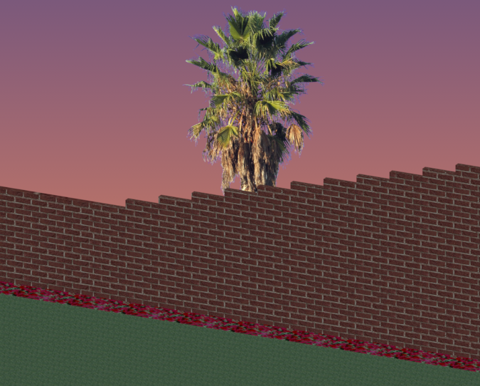
Landscape WallsThe Vectorworks Architect and Landmark programs include the ability to create a stepped wall. The Vectorworks Landmark program also contains the ability to create a retaining wall site modifier, and several ways of creating landscape walls with the landscape wall tools. The stepped wall and retaining wall site modifier are based on walls created with the Wall or Round Wall tool, offering the benefits and flexibility of the architectural wall tools.
~~~~~~~~~~~~~~~~~~~~~~~~~
 Creating
Stepped Walls
Creating
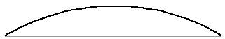
Stepped WallsStepped walls add wall peaks to existing walls created with the Wall tool or Round Wall tool. The existing wall can be a single wall or a chain of multiple wall segments that are L-joined to each other. Stepped walls can have a constant rise at each interval, or conform to underlying terrain with a variable rise, such as free-standing landscape walls or fences.
To create a stepped wall:
1. Select the wall or multiple, L-joined walls.
2. Select the Create Stepped Wall command from the appropriate menu:
• Architect: AEC > Create Stepped Wall
• Landmark: Landmark > Architectural > Create Stepped Wall
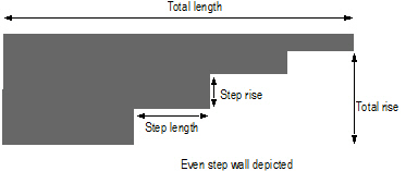
The Create Stepped Wall dialog box opens. Set the stair parameters.
The options available depend on the selected Step Style (even steps or terrain steps). If the parameters are set so that the steps are uneven, the top step is truncated.
Click to show/hide the parameters.
3. Click OK to create the stepped wall.
The Send to Surface command can be used on walls; it sets the bottom Z value at the start of the wall to the existing terrain surface (see “Sending Objects to the Site Model Surface” on page 703).
~~~~~~~~~~~~~~~~~~~~~~~~~
 Creating
Retaining Walls
Creating
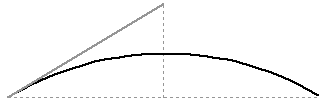
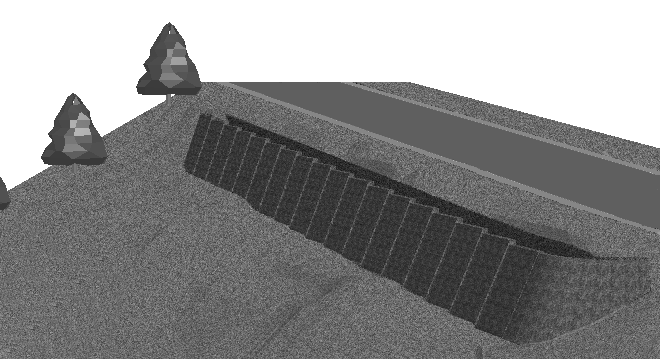
Retaining WallsA retaining wall site modifier can be created based on existing walls created with the Wall tool or Round Wall tool. The existing wall can be a single wall or a chain of multiple wall segments that are L-joined to each other. The retaining wall created can modify the site model, and the terrain can be sculpted as desired around the retaining wall.
Once created, the retaining wall site modifier is not associated with the wall object used to create it.
To create a retaining wall site modifier:
1. Select the wall or multiple, L-joined walls.
2. Select the Create Retaining Wall Site Modifier command from the appropriate menu:
• Designer: AEC > Terrain > Create Retaining Wall Site Modifier
• Landmark: Landmark > Create Retaining Wall Site Modifier
The Create Retaining Wall Site Modifier dialog box opens. Set the initial location of the site modifiers within the retaining wall. There are three distinct areas that can modify the site model:
• the pad at the bottom of the wall, which can be offset from the top or bottom of the wall, or simply follow the terrain
• the left and right side edges of the wall, which can be offset from the top or bottom of the wall, or follow the terrain
• the starting and ending edges of the wall
The left and right sides of the wall are determined by the wall direction as it was drawn.
Click to show/hide the parameters.
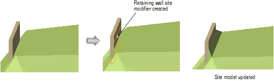
3. Click OK to create the retaining wall site modifier. The original wall(s) remain in the drawing; the site modifier is a new, separate object.
4. Update the site model to apply the changes (select the site model and click Update from the Object Info palette).
Retaining wall parameters can be edited from the Object Info palette.
Click to show/hide the parameters.
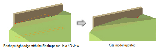
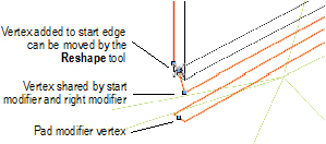
The retaining wall site modifier consists of four modifier edges, joined by common vertices. The left and right edges of the retaining wall site modifier can be reshaped with the Reshape tool, similar to reshaping walls (see “Reshaping Walls” on page 532). Move vertices, and add or delete vertices to reshape the retaining wall.
The start and end edges cannot be directly edited with the Reshape tool. However, a vertex added to the left or right edge can be edited by the Reshape tool (select Start/End Modifier Edge from the Move list in the Object Info palette, and click Add Vertex). Adding vertices to the start and end edges allows them to be reshaped as needed.
The Send to Surface command can be used to send either the retaining wall modifier edge or the pad to the surface of the site model.
~~~~~~~~~~~~~~~~~~~~~~~~~
 Landscape
Wall Tools
Landscape
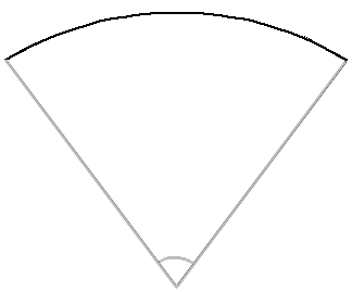
Wall ToolsThe Vectorworks Landmark program includes three tools for creating landscape walls.
A landscape wall object (retaining wall) can be set to be a site model modifier. It changes the proposed site model when the site model is updated.
To draw straight, arc, and Bézier landscape walls, either use the landscape wall tools, or draw a polyline and then select the Create Objects from Shapes command (see “Creating Objects from Shapes” on page 273). Place the different types of landscape walls next to each other to achieve a particular design or effect.
To create a row of straight and curved landscape walls, use the Create Objects from Shapes command.
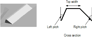
 Straight
Landscape Walls
Straight
Landscape Walls
To insert a straight landscape wall:
1. Click the Landscape Wall tool from the Site Planning tool set.
2. Click and drag to define the length and angle of the landscape wall. Click again to set the end point. If this is the first time the tool is used during this session, the Object Properties dialog box opens. Accept the default values and click OK.
The straight landscape wall parameters can be edited in the Object Info palette.
Click to show/hide the parameters.
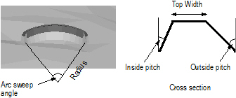
 Arc
Landscape Walls
Arc
Landscape Walls
To insert an arc landscape wall:
1. Click the Landscape Wall Arc tool from the Site Planning tool set.
2. Click to define the placement of the arc landscape wall and click again to set the rotation. If this is the first time the tool is used during this session, the Object Properties dialog box opens. Accept the default values and click OK.
The landscape wall arc parameters can be edited in the Object Info palette.
Click to show/hide the parameters.
 Bézier
Landscape Walls
Bézier
Landscape Walls
To insert a Bézier landscape wall:
1. Click the Landscape Wall Bézier tool from the Site Planning tool set.
2. Click and drag to define the length and angle of the landscape wall. Click again to set the end point. If this is the first time the tool is used during this session, the Object Properties dialog box opens. Accept the default values and click OK.
3. Adjust the control points of the Bézier wall by clicking and dragging to obtain the desired curvature.
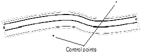
The Bézier landscape wall parameters can be edited in the Object Info palette.
Click to show/hide the parameters.
~~~~~~~~~~~~~~~~~~~~~~~~~
 Creating
Hardscape Objects
Creating
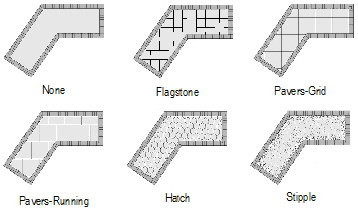
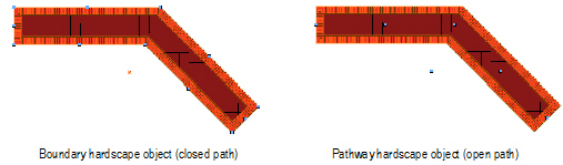
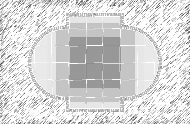
Hardscape ObjectsA hardscape object is comprised of paved areas with joint patterns and optional borders. A boundary hardscape or pathway hardscape can be created. To draw a hardscape object, either use the Hardscape tool, or create a polyline and then select the Create Objects from Shapes command (see “Creating Objects from Shapes” on page 273). The hardscape object can modify the site model.
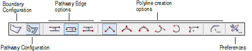
The following modes are available.
Mode |
Description |
|---|---|
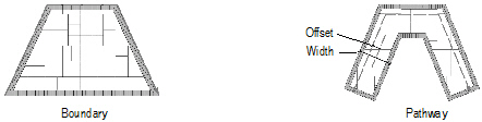
Boundary Configuration |
Creates a hardscape with a boundary configuration, defining an area with an optional border |
Pathway Configuration |
Creates a hardscape along a path |
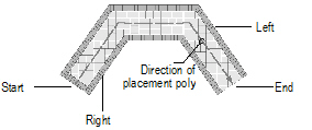
Pathway Edge options |
For the pathway configuration, sets where to create the pathway in relation to the drawn polyline |
Polyline creation options |
Selects the method for drawing the polyline upon which the hardscape object is based; see “Creating Polylines” on page 294. |
Preferences |
Sets the default preferences for the hardscape object |

To create a hardscape object:
1. Click the Hardscape tool from the Site Planning tool set.
2. Click Preferences from the Tool bar to specify the default Hardscape tool parameters for this session.
The Hardscape Object Settings dialog box opens. Enter the hardscape parameters.
Click to show/hide the parameters.
The Stipple joint patterns are a processor-intensive action for large hardscape objects and can significantly increase regeneration time.
When drawing a hardscape object with a curved boundary, speed the regeneration time by setting the 2D conversion resolution in Vectorworks preferences to low (see “Aba Edição” on page 47).
3. Click OK.
4. Click the appropriate mode in the Tool bar to specify the creation method of the hardscape object. Select whether to create a boundary or pathway hardscape object.
The hardscape configuration can also be changed after creation from either the Hardscape Object Settings dialog box or the hardscape context menu commands (see “Converting the Hardscape Object to a Boundary or Pathway Configuration” on page 749).
For information on the Polyline tool modes, see “Creating Polylines” on page 294.
5. Click to set the hardscape object’s start point.
6. Click to set the end of the segment and the beginning of the next. Continue drawing segments in this manner until the hardscape object is complete. Return to the start point (for boundary configurations), or simply double-click (for either pathway or boundary configurations) to finish creating the hardscape object.
7. When classing the subcomponents of the hardscape object, such as for the joints or tags, the class visibility of the specified class controls the visibility of the corresponding subcomponent. The class attributes are only applied to the corresponding subcomponent when the Use at Creation option is selected for the class. For example, if the Joint Class is set to the Site-Hardscape Comp-Main Joint class, and that class specifies a hatch Fill Style, edit the class and select the Use at Creation option to apply the fill attribute.
8. If the hardscape 3D Type is set to Pad Modifier or Texture Bed Modifier, update the site model to apply the modification. Select the site model and click Update from the Object Info palette.
Click here for a video tip about this topic (Internet access required).
~~~~~~~~~~~~~~~~~~~~~~~~~
 Editing
the Hardscape Object Settings
Editing
the Hardscape Object SettingsThe parameters can be edited for selected hardscape objects through the Hardscape Settings button on the Shape tab of the Object Info palette. To modify the default hardscape object settings, click the Preferences button on the Tool bar.
Many of the parameters are identical to those used to create the hardscape object (see “Creating Hardscape Objects” on page 743). However, certain parameters are accessible in the Object Info palette only.
Click to show/hide the parameters.
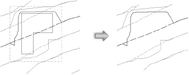
To set individual border segments to invisible for boundary hardscapes or cut-out holes, select the hardscape object, and then click the Reshape tool. Select Hide or Show Edges mode. Click the midpoint of the hardscape border segments or the cut-out hole to hide. Repeat this process to set the border segments back to visible, if necessary.
To quickly determine the left and right side of a pathway hardscape object, select the hardscape object and click the middle button next to the Vertex field on the Shape tab of the Object Info palette; while the button is clicked, the first vertex of the hardscape object is highlighted with a red box.
When classing the subcomponents of the hardscape object, such as for the joints or tags, the class visibility of the specified class controls the visibility of the corresponding subcomponent. The class attributes are only applied to the corresponding subcomponent when the Use at Creation option is selected for the class. For example, if the Joint Class is set to the Hardscape - Component - Main Joint class, and that class specifies a hatch Fill Style, edit the class and select the Use at Creation option to apply the fill attribute. See “Setting Class Attributes” on page 176.
Double-click the hardscape object to activate the Reshape tool, or select the Reshape tool from the Basic palette. Select the object handles to reshape the hardscape object. For more information, see “Remodelando Objetos” on page 1041.
After creation, a boundary hardscape object can be converted to a pathway hardscape object, and similarly, a pathway configuration can be converted to a boundary configuration. The conversion preserves the appearance, but the path of the object changes.
To convert a boundary hardscape object to a pathway hardscape configuration:
1. Select the boundary hardscape object.
2. Right-click (Windows) or Ctrl-click (Mac) on the hardscape object and select Convert to Pathway from the context menu.
To convert a pathway hardscape object to a boundary hardscape configuration:
1. Select the pathway hardscape object.
2. Right-click (Windows) or Ctrl-click (Mac) on the hardscape object and select Convert to Boundary from the context menu.
Alternatively, click Hardscape Settings from the Object Info palette of a selected hardscape object, and select the configuration.
Hardscape tags can be adjusted in several ways.
• When hardscape tags are required, their default appearance is normally specified in the hardscape object settings.
• Individual hardscape tags can then be changed for selected hardscape objects by adjusting the hardscape tag parameters in the Object Info palette.
• The hardscape tag class controls the appearance of the leader/shoulder lines, as well as the marker style.
• To align hardscape tags for improved readability, use the Align/Distribute Leader Lines command (see “Alinhando e Distribuindo Linhas de Indicação” on page 1032).
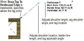
• If an individual tag needs to be repositioned, hardscape tags also have two control points for adjusting the shoulder length, tag shoulder angle, and tag location; or the shoulder location, leader line length, and tag approach angle.
Once the hardscape object is set to the desired appearance, the settings can be saved for future use or importing into other files, by saving the hardscape object. When you insert a hardscape from the Resource Browser, all its object settings are preset.
To save the selected hardscape object settings:
1. Select a hardscape object.
2. In the Object Info palette, click Save Hardscape.
The Enter String dialog box opens.
3. Enter a unique name.
4. Click OK.
The hardscape object is saved in the “Hardscapes” symbol folder in the Resource Browser. Boundary and pathway hardscape objects are assigned unique thumbnail view icons for easy identification. For more information on the Resource Browser, see “Using the Resource Browser” on page 217.
5. To use a saved hardscape object, double-click on it in the Resource Browser. Alternatively, drag the saved hardscape onto an existing hardscape to apply the saved settings.
~~~~~~~~~~~~~~~~~~~~~~~~~
 Editing
Hardscape Object Fills
Editing
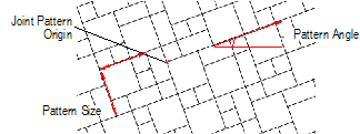
Hardscape Object FillsHardscape object fills can be changed through the Attributes palette. If a joint pattern was specified, the joint pattern is drawn over the fill attribute of the hardscape object. The main joint pattern origin is editable and has a control point marked with a red locus for identification; the border joint pattern uses a green locus.
To change the appearance of a hatch fill, edit the hatch definition as described in “Editando Hachuras” on page 1108. Change the size or angle of a hatch fill by temporarily switching to a Pavers-Running pattern, setting the Pattern Size X, Y and/or Pattern Angle values, and then switching back to the selected hatch.
Hardscape objects can also use images and gradients as fills. Use the Attribute Mapping tool to adjust the fill direction and size. For more information on using image or gradients, see “A Paleta de Atributos” on page 1091; for more information on using the Attribute Mapping tool, see “Mapeando Preenchimentos com a Ferramenta Mapeamento de Atributos” on page 1119.
If the subcomponents of the hardscape object are classed, such as for the joints or tags, the class visibility of the specified class controls the visibility of the corresponding subcomponent. The class attributes are only applied to the corresponding subcomponent when the Use at Creation option is selected for the class. For example, if the Joint Class is set to the Hardscape - Component - Main Joint class, and that class specifies a hatch Fill Style, edit the class and select the Use at Creation option to apply the fill attribute. See “Setting Class Attributes” on page 176.
The angle or origin point of a hardscape fill can be adjusted. Move the control point at the center of the hardscape to control the origin point of the paving pattern (including a hatch) and change the Joint Pattern Angle value to adjust the angle.
When joining bordered hardscape objects with similar borders, use the Add Surface command (see “Adicionar Surperfícies” on page 1076).
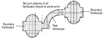
To coordinate the joint patterns of several hardscape objects, configure the hardscape objects with the same settings and drag their main pattern origin control points (marked with the red locus) to a common location.
~~~~~~~~~~~~~~~~~~~~~~~~~
 Showing
and Hiding Site Modifiers
Showing
and Hiding Site ModifiersSite modifiers, such as pads, grade limits, and portions of roads and landscape walls can be made hidden or visible. The modifications to the proposed site model are still visible even when the modifier is hidden.
To show or hide site model modifiers:
1. Select View > Show > Show or Hide Site Modifiers.
2. If site modifiers were hidden, they are displayed; if they were visible, they become hidden.
 Correcting
Site Modifier Errors
Correcting
Site Modifier ErrorsIf site modifier errors are detected when the site model is updated, an icon displays at the location of each error.
The following modifier problems can generate errors:
• Pad which does not lie inside the grade limits
• Pad intersecting grade limits or the site border
• Two intersecting pads
• Spoil pile intersecting the site border
• Spoil pile intersecting grade limits or the site border
• Two intersecting spoil piles
• Texture bed intersecting the site border
• Two intersecting texture beds
• Locus which does not lie inside the grade limits
If these errors exist, the site model can still be modified; however, results may not be as expected. It may be better to resolve the errors and update the site model again before proceeding.
When the site model object is selected, the Object Info palette’s Error Count field displays the number of errors, and an icon displays at the location of each error. Hold the cursor over an icon to display a SmartCursor cue that describes the error. Resolve the errors by making adjustments to prevent all intersecting modifiers.
![]()
To hide the icons from view (but not resolve the underlying errors), deselect Show Errors on the site model’s Object Info palette.
Update the site model to ensure that all errors have been corrected.
~~~~~~~~~~~~~~~~~~~~~~~~~
 Drawing
Property Lines
Drawing
Property LinesUse the Property Line tool to draw property lines. Alternatively, use one of the following methods.
• Draw a polyline and then select the Create Objects from Shapes command (see “Creating Objects from Shapes” on page 273).
• Draw arcs and lines, select Modify > Compose to create a single polyline, and then select the Create Objects from Shapes command.
Click here for a video tip about this topic (Internet access required).
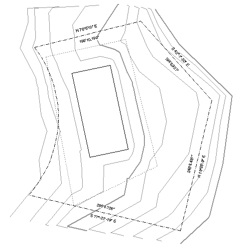
The Property Line tool interactively creates property boundaries from surveyor’s descriptions. The resulting polyline is composed of line and/or arc segments. The closing error can be automatically drawn and measured. Each segment can be individually labeled with distance and bearing; a curve data worksheet displays curve data.

To create property lines using the Property Line tool:
1. Click the Property Line tool from the Site Planning tool set.
2. Click to set the starting point of the first property segment.
A red bull’s-eye is placed on the drawing to mark the starting point; the Define Property Line dialog box opens.
3. Specify the segment parameters and click Add to update the drawing file; the bull’s-eye cursor moves to the end of the segment. Continue to add or remove segments as needed.
Click to show/hide the parameters.
4. Click OK to create the property line.
If this is the first time the Property Line tool has been used, the Object Preferences dialog box opens. Accept the defaults and click OK.
To create property lines by drawing a path object, rather than specifying parameters in a dialog box, add the Property Line object to the workspace through the Workspace Editor; see “Modifying Tool Palettes and Tool Sets” on page 1832. Once added to the workspace, click the Property Line object and draw the path object(s) as desired.
~~~~~~~~~~~~~~~~~~~~~~~~~
 Editing
Property Lines
Editing
Property LinesEdit property lines by using the Reshape tool, or by clicking the Edit with Dialog button in the Object Info palette. Additional parameters can also be modified in the Object Info palette. See “Remodelando Objetos” on page 1041 for information on using the Reshape tool for editing.
To edit property lines using the Object Info palette:
1. Select the property line.
2. Modify the parameters in the Object Info palette.
Click to show/hide the parameters.
For information on editing object vertices, see “Remodelando Objetos” on page 1041.
3. If the property line was designated to be a texture bed on the site model, select Tools > Organization. On the Classes tab, select the class designated as the texture bed class, and assign it a distinctive fill color, or, if the Renderworks product is installed, a texture. Select the site model and click Update from the Object Info palette; the property line displays as a texture bed on the site model. Switch to a 3D view and render for the full effect.
4. When Annotate Segments is selected and curve data exists, a curve data worksheet is automatically created, showing curve data in worksheet form. Select Window > Worksheets to display the worksheet, or view it from the Resource Browser.
~~~~~~~~~~~~~~~~~~~~~~~~~
 Analyzing
the Site Model
Analyzing
the Site ModelThe individual cut and fill calculations for a site model can be listed in a report for verification.
To list site model volume:
1. Select the site model to analyze. Only one site model can be analyzed at a time.
2. Select the Create Site Volume List command from the appropriate menu:
• Architect AEC > Terrain > Create Site Volume List
• Landmark: Landmark > Create Site Volume List
The Create Site Model Volume List dialog box opens. On the Columns tab, select the columns of site model data to include in the report.
Click to show/hide the parameters.
3. On the Grade Limits Modifiers tab, select the grade limits site modifiers to include in the report calculations.
Click to show/hide the parameters.
4. On the Options tab, choose report output parameters.
Click to show/hide the parameters.
5. Click OK to create the site model volume report.
 Zone
of Visual Influence Analysis
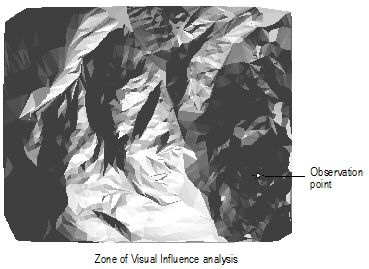
Zone
of Visual Influence AnalysisThis type of analysis creates a representation of shadowed and lighted areas as seen from a specified point of view.
To perform a zone of visual influence analysis:
1. Select the site model to analyze.
2. Select the Zone of Visual Influence command from the appropriate menu:
• Designer: AEC > Terrain > Zone of Visual Influence
• Landmark: Landmark > Zone of Visual Influence.
The Zone of Visual Influence dialog box opens. Specify the analysis parameters.
Click to show/hide the parameters.
3. Click OK.
4. Click on the site model to indicate the observation point.
5. Click again to perform the analysis.
A light source is automatically inserted, and the layer is rendered to complete the analysis. Dark regions indicate areas that cannot be seen from the specified observation point at that viewing level.
~~~~~~~~~~~~~~~~~~~~~~~~~
 Obtaining
Site Model Data
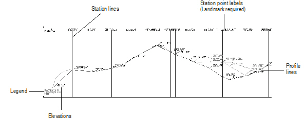
Obtaining
Site Model DataUse the Site Model Section command to create a profile or sectional views of the site.
To create a site model section:
1. Draw or select a 2D polygon or polyline to define the section alignment. In the Vectorworks Landmark product, if you are selecting a previously drawn polyline with station points (such as a road or Roadway (NURBS) object), a station point profile can be created.
The polygon or polyline vertices must be contained within the limits of the site model.
2. With the polygon or polyline selected, select the Site Model Section command from the appropriate menu:
• Architect: AEC > Terrain > Site Model Section
• Landmark: Landmark > Site Model Section
The Create Site Model Section dialog box opens. Specify the site model section parameters.
Click to show/hide the parameters.
The Site Model Section Formatting dialog box opens. Specify the formatting for the site model section graphic.
Click to show/hide the parameters.
4. Click OK to return to the Create Site Model Section dialog box.
5. Click OK to create the sectional view of the site. If the site model changes, the site model section needs to be recreated.
~~~~~~~~~~~~~~~~~~~~~~~~~
 Calculating Grade
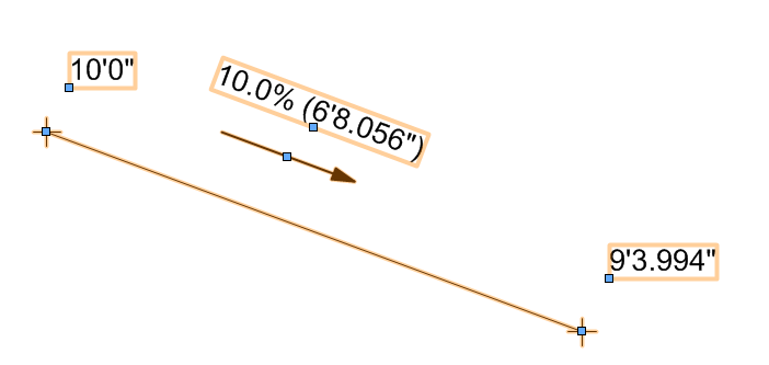
The Grade tool annotates terrain slopes on site plan documents.
Networks of grade objects can be created to show slope characteristics across a surface. Grade objects can be used in conjunction with a site model, and can modify the site model. In addition, 3D loci can be generated from grade object elevations, and used as the basis of creating a site model.
The Grade tool has three modes:
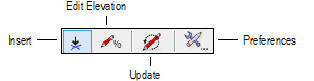
Mode |
Description |
|---|---|
Insert |
Draws a grade object based on set elevation parameters or a site model |
Edit Elevation |
Changes the elevation value of one or more existing grade objects |
Update |
Updates all grade objects in the drawing, applying current preference settings and updating any overlapped elevation points |
Preferences |
Sets the default global preferences for the grade object |
~~~~~~~~~~~~~~~~~~~~~~~~~
 Specifying
Global Grade Object Preferences
Specifying
Global Grade Object PreferencesThe grade indicator appearance for all grade objects in the file can be specified globally.

To set global grade object appearance:
1. Click the Grade tool from the Site Planning tool set.
2. Click Preferences from the Tool bar. Alternatively, select an existing grade object; click Settings from the Object Info palette, double-click the grade object, or right-click (Windows) or Ctrl-click (Mac) on a grade object and select Edit from the context menu.
The Grade Settings dialog box opens. Click the Global Settings tab and enter the desired settings.
Click to show/hide the parameters.
3. Click OK to set the global grade indicator attributes.
4. Click Update from the Tool bar to update all grade objects in the drawing with the global settings.
~~~~~~~~~~~~~~~~~~~~~~~~~
 Inserting
Grade Objects
Inserting
Grade Objects
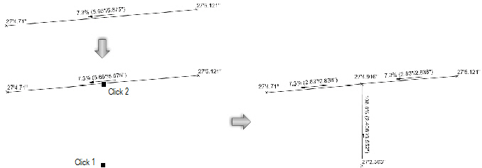
To insert a grade object:
1. Click the Grade tool from the Site Planning tool set, and select Insert mode from the Tool bar.
2. Click to set the start of the grade. Move the mouse and click again to set the end point.
The Grade Settings dialog box opens. Click the Object Properties tab and enter the desired settings.
Click to show/hide the parameters.
3. Click OK.
Grade objects can be edited from the Object Info palette. Commonly-required parameters can be accessed directly from the Object Info palette, or click Settings to change any of the parameters of selected grade objects. Alternatively, edit the settings of a grade object by double-clicking on it, or right-click (Windows) or Ctrl-click (Mac) on a grade object and select Edit from the context menu.
Grade objects can be used together, using an existing grade object as a reference for another grade object. Either move the endpoint of one grade object onto the line of another grade object, or create a new grade object with an end point on an existing grade object. The existing grade object is split at the new endpoint, creating a network of overlapping grade objects. The elevation of the shared point is interpolated from the slope of the existing object; if an elevation point is updated, all overlapping grade objects automatically update. Click Update mode from the Tool bar of the Grade tool to force an update of all overlapping grade objects.
~~~~~~~~~~~~~~~~~~~~~~~~~
 Editing
Elevation
Editing
ElevationIf the elevation changes after one or more grade objects have been placed, there is no need to replace the existing grade object(s). Change the elevation of one end of a grade object, or offset the elevation of selected (or all) grade objects in the drawing.
Elevation marker symbols must be at a valid scale to edit elevations. If the Edit Elevation dialog box does not open, increase the marker scale factor for the grade object.

To edit grade object elevation:
1. Click the Grade tool from the Site Planning tool set, and select Edit Elevation mode from the Tool bar.
2. Click at the start or end of a grade object.
On the Edit Elevation dialog box, edit the grade as needed.
Click to show/hide the parameters.
3. Click OK to edit the elevation of the grade object(s).
~~~~~~~~~~~~~~~~~~~~~~~~~
 Analyzing
Grade
Analyzing
GradeGrade objects can be used to analyze the slope objects in a drawing and identify critical slopes. Grade objects that are outside specified slope or elevation ranges are highlighted or selected.

To perform a grade analysis:
1. Click the Grade tool from the Site Planning tool set.
2. Click Preferences from the Tool bar. Alternatively, click Settings from the Object Info palette of a selected grade object.
The Grade Settings dialog box opens. Click the Global Settings tab and specify the grade analysis parameters.
Global attribute display of the slope indicator is described in “Specifying Global Grade Object Preferences” on page 762
Click to show/hide the parameters.
3. Click OK. Grade objects that do not meet the criteria are considered critical, and are highlighted and/or selected, as specified.
~~~~~~~~~~~~~~~~~~~~~~~~~
 Creating
Loci from a Grade Object
Creating
Loci from a Grade ObjectOne or more grade object(s) can be used to place 3D loci on the current layer. The 3D loci can then be used to create stake objects or a site model.
To create 3D loci from stake object elevations:
1. Select one or more grade objects.
2. Select the Create 3D Loci at Grade Points command from the appropriate menu:
• Designer: AEC > Terrain > Create 3D Loci at Grade Points
• Landmark: Landmark > Create 3D Loci at Grade Points
A 3D locus is placed at the ends of each selected grade object. The Z-value of the loci match the associated elevation of the grade start or end point.
~~~~~~~~~~~~~~~~~~~~~~~~~
 Inserting
Stake Objects
Inserting
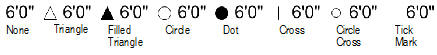
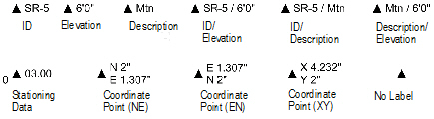
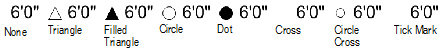
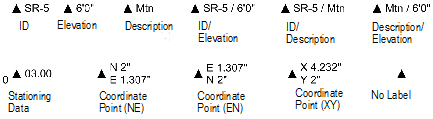
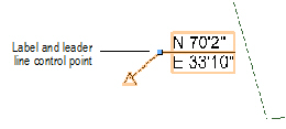
Stake ObjectsStake objects represent a 3D point in space, with text to display the elevation, coordinate points, or other information. Using a stake object, the elevation information for a point on the site model can be determined and labeled. A stake object can be used as a site modifier. If the design layer is georeferenced, a stake object can be used as a geographic marker.
The following modes are available.
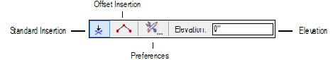
Mode |
Description |
|---|---|
Standard Insertion |
Inserts a single stake object |
Offset Insertion |
Inserts a stake at each vertex of the drawn polygon shape |
Preferences |
Sets the default preferences for the stake object |
Elevation |
Sets the default elevation value for stake objects |

To insert a stake object:
1. Click the Stake tool from the Site Planning tool set, and select the mode from the Tool bar.
2. Click on the site model to place the stake object, or draw a temporary polygon to place a series of stake objects at each click point and double-click to end the series.
If this is the first time the Stake tool has been used, the Object Properties dialog box opens. Accept the defaults and click OK.
To automatically increment the ID parameter when placing new stake objects, select Auto ID Numbering and specify an Initial ID Number. Otherwise, leave Auto ID Numbering unselected and specify the default ID Number for stake objects.
3. The stake objects are added to the drawing at the elevation specified in the Tool bar.
Select the Send to Surface command to set the stake elevation to that of the site model surface (see “Sending Objects to the Site Model Surface” on page 703).
4. If the stake objects are site modifiers, update the site model to apply the changes (select the site model and click Update from the Object Info palette.).
5. Move the control point to adjust the label and leader line position. If there are several stake objects, use the Align/Distribute Leader Lines command to improve readability (see “Alinhando e Distribuindo Linhas de Indicação” on page 1032).
6. The stake properties can be edited in the Object Info palette.
Click to show/hide the parameters.
~~~~~~~~~~~~~~~~~~~~~~~~~
 Converting
3D Loci to Stake Objects
Converting
3D Loci to Stake Objects3D loci can be converted to stake objects, which can then be used to modify a site model. This is useful when survey data, in the form of 3D loci, need to modify an existing or proposed site model.
To create stake objects from 3D loci:
1. Select the 3D loci.
2. Select Modify > Convert > Stake Object from 3D Locus.
The Convert to Stake Object dialog box opens. Set the properties for new stakes.
Click to show/hide the parameters.
3. Click OK to create the stake objects.
If the stake objects are site modifiers, update the site model to apply the changes (select the site model and click Update from the Object Info palette).
See “Inserting Stake Objects” on page 767 for additional stake object parameters that can be edited from the Object Info palette.
~~~~~~~~~~~~~~~~~~~~~~~~~