Modo
Ferramenta
Conjunto
Modo para Creating Lines
Linha de Indicação Simples

Básica
O produto Vectorworks Fundamentals provê um objeto linha de indicação básica. Na configuração do Vectorworks Design Series, a linha de indicação inclui parâmetros adicionais.
Modo |
Ferramenta |
Conjunto |
|---|---|---|
Modo para Creating Lines |
Linha de Indicação Simples
|
Básica |
A ferramenta Linha de Indicação Simples compartilha a mesma posição na paleta Básica com outra ferramenta. Clique e segure o mouse na ferramenta visível para abrir a lista de ferramentas de pop-out e selecione a ferramenta desejada.
Para criar uma linha de indicação nas configurações Fundamentals:
1 Clique na ferramenta Linha de Indicação Simples da paleta ferramentas Básicas e selecione o modo Constrained ou Livre Constrained da barra de Ferramentas.
2 Clique para definir o inicio da linha de ombro; clique para definir o fim do ombro e inicio da linha de indicação.
3 Clique novamente para definir o ponto final da linha de indicação.
Por definição, um marcador seta preenchida é posicionado ao fim da linha de indicação. Um marcador diferente pode ser selecionado na paleta Atributos (veja Marker Attributes).
 Inserindo
uma Linha de Indicação Design Serie
Inserindo
uma Linha de Indicação Design Serie Modo |
Ferramenta |
Conjunto de Ferramentas |
|---|---|---|
Modo para The Symbol Insertion Tool |
Linha de Indicação
|
Básica |
A ferramenta de linha de indicação e a ferramenta de texto explicativo compartilham a mesma posição na paleta básica. Clique e segure o mouse na ferramenta visível para abrir a lista de ferramentas de pop-out e selecione a ferramenta desejada.
Para criar uma linha de indicação em uma configuração Design Series:
1 Clique na ferramenta Linha de Indicação da paleta ferramentas Básicas.
2 Clique para posicionar o objeto no desenho, e clique novamente para configurar a rotação.
3 A primeira vez que você utilizar a ferramenta em um arquivo, uma janela de diálogo propriedades abrirá. Configure as propriedades padrões, e clique OK. As propriedades podem ser editadas a partir da paleta informações de Objeto.

► Clique para exibir/ocultar parâmetros
Após o posicionamento, os pontos de controle no marcador e no ombro permitem que a linha de indicação seja reposicionada.
Se existirem muitos objetos linha de indicação, utilize o comando Alinhar/Distribuir Linhas de Indicação para melhorar a legibilidade.
~~~~~~~~~~~~~~~~~~~~~~~~~
Várias ferramentas no produto Vectorworks Fundamentals adiciona informação de conjunto a um desenho com objetos preformatados. O produto Vectorworks Design Series oferece ferramentas para objetos de anotações acicionais.
~~~~~~~~~~~~~~~~~~~~~~~~~
Ferramenta |
Conjunto de Ferramentas |
|---|---|
Balões de Revisão
|
Dims/Notes |
Use a ferramenta de Balões de Revisão para identificar uma seção do desenho que mudou. Insira um balão de revisão em uma área do desenho, ou ao redor de uma porção inteira do desenho, se apropriado.
Para os produtos Vectorworks Design Series, balões de revisão podem também ser criados primeiramente desenhando uma polilinha e então selecionando Creating Objects from Shapes).

Modo |
Descrição |
|---|---|
Oval |
Insere o balão de revisão em volta do perímetro da oval prevista. Clique para ajustar o ponto inicial, mova o cursor na direção desejada, e clique para colocar o ponto final. Limite a oval a 45 graus para desenhar um círculo.
|
Retangular |
Insere o balão de revisão em volta do perímetro do retângulo previsto. Clique para ajustar o ponto inicial, mova o cursor na direção desejada, e clique para colocar o ponto final. Limite a oval a 45 graus para desenhar um quadrado.
|
Polígono Regular
|
Insere o balão de revisão ao redor do perímetro dos vértices especificados. Clique para posicionar o ponto de partida (primeiro vértice), clique na posição desejada para cada um dos vértices subsequentes, e ou clique no primeiro vértice para fechar o polígono ou faça um duplo clique no último vértice para criar um polígono aberto. Se o polígono for aberto, o balão de revisão será completado com base no contorno.
|
Polígono a Mão Livre
|
Insere o balão de revisão ao redor do perímetro dos vértices especificados. Clique para posicionar o ponto inicial e clique-arraste para desenhar o polígono a mão livre. Se o polígono for aberto, o balão é completado com base no contorno.
|
Para criar um balão de revisão:
1. Clique na ferramenta Balão de Revisão do conjunto de ferramentas Cotas/Anotações.
2. Clique o botão de Preferências na barra de Ferramentas para definir as propriedades do balão de revisão. As propriedades podem ser também ajustadas após colocação, a partir da paleta Informações do Objeto. Clique OK.
3. Selecione o modo balão de revisão e selecione para desenhar o balão com forma convexa ou côncava. A forma convexa desenha curvas para fora da imagem prevista ou dos vértices especificados. A forma côncava desenha curvas para dentro da imagem prevista ou dos vértices especificados.
4 Clique para desenhar o balão de revisão de acordo com o modo especificado.
► Clique para exibir/ocultar parâmetros
A ilustração seguinte demonstra o efeito de variar os parâmetros de tamanho e variação da curva.

~~~~~~~~~~~~~~~~~~~~~~~~~
Modo |
Ferramenta |
Conjunto de Ferramentas |
|---|---|---|
Modo para The Symbol Insertion Tool |
Rótulo do Desenho
|
Dims/Notes |
Use a ferramenta Rótulo do Desenho para adicionar informações descritivas a um desenho. Por padrão, um objeto de rótulo inclui um título, a escala do desenho e um número atribuído automaticamente. O número da folha que contém o desenho pode também ser incluído na etiqueta. Os valores padrão para o título, número do desenho, e número da folha depender de onde o rótulo é colocado: em uma camada design, ou em uma anotação de janela de exibição, por exemplo.
Rótulos de desenho mantem um tamanho constante independentemente da escala do desenho.
Para criar um rótulo do desenho:
1 Clique na ferramenta de Rótulo do Desenho a partir do conjunto de ferramentas Cotas/Anotação.
2 Clique para colocar o objeto no desenho, e clique novamente para definir a rotação.
3 A primeira vez que você usar a ferramenta em um arquivo, uma caixa de diálogo Propriedades é aberta. Defina as propriedades padrão e clique em OK.As propriedades podem ser editadas a partir da paleta Informações do Objeto.
► Clique para exibir/ocultar parâmetros
~~~~~~~~~~~~~~~~~~~~~~~~~
Mode |
Tool |
Tool set |
|---|---|---|
Modes for The Symbol Insertion Tool |
Reference Marker
|
Dims/Notes |
Use the Reference Marker tool to indicate the drawing number and sheet number of a referenced drawing, in a variety of configurations.
Reference markers maintain a constant size regardless of the drawing scale.
To create a reference marker:
1 Click the tool and mode.
2 Click to place the object in the drawing, and click again to set the rotation. The first time you use the tool in a file, a properties dialog box opens. Set the default properties. The properties can be edited from the Object Info palette.
► Clique para exibir/ocultar parâmetros
~~~~~~~~~~~~~~~~~~~~~~~~~
 Creating North
Arrows
Creating North
Arrows Mode |
Tool |
Tool set |
|---|---|---|
Modes for The Symbol Insertion Tool |
North Arrow
|
Dims/Notes |
Use the North Arrow tool to indicate the drawing orientation, in a variety of configurations. The deviation from true magnetic north can be displayed on some of the configurations. If the design layer is georeferenced, the object is rotated to point in the proper direction.
North arrows maintain a constant size regardless of the drawing scale.
To create a north arrow:
1 Click the tool and mode.
2 Click to place the object in the drawing, and click again to set the rotation. The first time you use the tool in a file, a properties dialog box opens. Set the default properties. The properties can be edited from the Object Info palette.
► Clique para exibir/ocultar parâmetros
~~~~~~~~~~~~~~~~~~~~~~~~~
 Creating
Elevation Benchmarks
Creating
Elevation Benchmarks Mode |
Tool |
Tool set |
|---|---|---|
Modes for Creating Lines |
Elevation Benchmark
|
Dims/Notes |
Use the Elevation Benchmark tool to indicate the height of an object in an elevation drawing. Two elevation benchmark styles are available: ISO and US.
To create an elevation benchmark:
1 Click the tool and mode.
2 Click to place the object in the drawing, and click again to set the rotation. The first time you use the tool in a file, a properties dialog box opens. Set the default properties. The properties can be edited from the Object Info palette.

► Clique para exibir/ocultar parâmetros
After creation, multiple elevation benchmark objects can be aligned and distributed with the Align/Distribute Leader Lines command; see Aligning and Distributing Leader Lines.
~~~~~~~~~~~~~~~~~~~~~~~~~
 Indicating
the Slope of Surfaces
Indicating
the Slope of Surfaces Mode |
Tool |
Tool set |
|---|---|---|
Modes for Creating Lines |
Slope Dimension
|
Dims/Notes |
Use the Slope Dimension tool to indicate the slope of any angle that is perpendicular to the screen.
To create a slope indicator:
1 Click the tool and mode.
2 Click to place the object in the drawing, and click again to set the rotation. The first time you use the tool in a file, a properties dialog box opens. Set the default properties. The properties can be edited from the Object Info palette.


► Clique para exibir/ocultar parâmetros
~~~~~~~~~~~~~~~~~~~~~~~~~
 Placing
a Dimension Tape
Placing
a Dimension TapeMode |
Tool |
Tool set |
|---|---|---|
Modes for Creating Lines |
Dimension Tape
|
Dims/Notes |
Spotlight software users can place a dimension tape object on the drawing to quickly indicate the approximate location of objects that don’t require final alignment until after installation is completed.
|
Click here for a video tip about this topic (internet access required). |

To place a dimension tape:
1 Click the tool and mode.
2 Click to place the object in the drawing, and click again to set the rotation. The first time you use the tool in a file, a properties dialog box opens. Set the default properties. The properties can be edited from the Object Info palette.
The dimension tape’s text font, size, and style are controlled with the Text menu, and attributes such as pen color, line type, and fill are controlled with the Attributes palette.
► Clique para exibir/ocultar parâmetros
3 If you need to indicate a specific location on the tape to mark the placement of an item, right-click on the dimension tape object and select Add Specific marker from the context menu.
The specific marker is a separate object from the dimension tape it is associated with, and its pen, line type, and fill attributes are edited independently. The placement of the specific marker and the length of its line can be edited with control points, and its position on the tape can be modified in the Object Info palette. To remove a specific marker, move its control point past the end of the dimension tape object, or select it and press the Delete key.
~~~~~~~~~~~~~~~~~~~~~~~~~
Mode |
Tool |
Tool set |
|---|---|---|
Modes for The Symbol Insertion Tool |
Scale Bar
|
Dims/Notes |
Use the Scale Bar tool to indicate the scale of the drawing objects. To include a scale bar for a viewport, select Modify > Edit Viewport, and place the scale bar as a viewport annotation.
To create a scale bar:
1 Click the tool and mode.
2 Click to place the object in the drawing, and click again to set the rotation. The first time you use the tool in a file, a properties dialog box opens. Set the default properties. The properties can be edited from the Object Info palette.
► Clique para exibir/ocultar parâmetros
~~~~~~~~~~~~~~~~~~~~~~~~~
 Creating
Grid Bubbles
Creating
Grid BubblesMode |
Tool |
Tool set |
|---|---|---|
Modes for the Polyline Tool |
Grid Bubble
|
Dims/Notes |
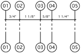
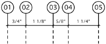
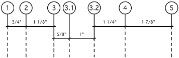
Grid bubble objects are dimensioned grid lines with bubble markers. This type of drawing notation can help locate columns and other primary building features on construction documents.
Grid marker objects maintain a constant size regardless of the drawing scale.
To create a grid bubble:
1 Click the tool and mode.
2 Place a line of grid bubbles by drawing an open polygon with the tool. The first click starts the grid line; the second click determines the angle of the grid line and sets a marker at that location. Each remaining click sets a grid marker.
3 Double-click to end the grid line. The first time you use the tool in a file, a properties dialog box opens. Set the default properties. The properties can be edited from the Object Info palette.
► Clique para exibir/ocultar parâmetros
Combine several bubble grids and adjust the labeling properties to create hierarchical (nested) grids.
~~~~~~~~~~~~~~~~~~~~~~~~~
Mode |
Tool |
Tool set |
|---|---|---|
Modes for Creating Lines |
Symmetry Label
|
Dims/Notes |
In some drawing standards, when drawing a building or object that is in complete symmetry, the designer may draw only half of the model and insert a symmetry label to indicate the symmetry line.
Symmetry labels maintain a constant size regardless of the drawing scale.
To create a symmetry label:
1 Click the tool and mode.
2 Click to place the object in the drawing, and click again to set the length and rotation.
~~~~~~~~~~~~~~~~~~~~~~~~~
 Error/Revision Management Using
Redlines
Error/Revision Management Using
Redlines
The Redline tool is in the Dims/Notes palette.
Use the Redline tool and commands to annotate drawings with redlines and sketches, and to keep track of redline objects and any corrections and revisions that occur in a drawing.
~~~~~~~~~~~~~~~~~~~~~~~~~
 Placing Redlines
 Tool |
Tool set |
|---|---|
Redline
|
Dims/Notes |
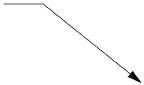
Use the Redline tool to create redline objects, which are graphical time-stamped change requests on the drawing.
Several modes are available.

To redline an object or area:
1 Click the tool and mode, and then click Preferences to specify the Redline tool Parâmetros for this session.
The Place Redline dialog box opens; set the Parâmetros.
► Clique para exibir/ocultar parâmetros
2 On the design layer where the revision is to be performed, draw the redline around the revision area.
Based on the selected creation method, the appropriate tool creates the redline. This allows the use of SmartCursor cues, object snapping, and boomerang mode when drawing redlines.

3 The Place Redline dialog box opens. Enter the redline information and authorization.
► Clique para exibir/ocultar parâmetros
4 The redline object indicates the current date and the drawing condition to be corrected. Position redline text by clicking on the tag control point and dragging the tag to the desired location. If there are several redline objects, use the Align/Distribute Leader Lines command to improve readability (see Aligning and Distributing Leader Lines).

The Parâmetros of one or more selected redline objects can be edited from the Object Info palette.
► Clique para exibir/ocultar parâmetros
~~~~~~~~~~~~~~~~~~~~~~~~~
 Attaching
a Sketch to a Redline
Attaching
a Sketch to a RedlineTool |
Tool set |
|---|---|
Redline
|
Dims/Notes |
In screen plane mode, one or more selected objects can be attached to a redline object to illustrate the redline comments. The object to be attached as a sketch must be selected before drawing the redline; this process converts the selected object to a sketch symbol and places it in a Redline Sketches symbol folder saved with the file.
To attach a selected object as a redline sketch:
1 Switch to the screen plane (see Planar Modes of 2D Objects: Screen Plane and Layer Plane).
2 Select the object to be converted to a sketch.
3 Click the tool, and draw the redline as described in Placing Redlines.
The Place Redline dialog box opens.
4 Select Attach the current selection as a sketch.
5 The selection is converted to a symbol that is attached to and moves with the redline object.
The sketch can be hidden by deselecting Show Sketch from the Object Info palette.
~~~~~~~~~~~~~~~~~~~~~~~~~
 Show or Hide Redlines
 Command |
Path |
|---|---|
Show or Hide Redlines |
Text > Redlines |
Over the course of a project, most drawings receive a large number of redlines, which, if left visible, would clutter the drawing. Select the command to toggle redline visibility.
All Redline objects are drawn in the Notes-Redlines class. If redlines are hidden when a new redline is drawn, the Notes-Redlines class visibility is automatically turned on and all the redlines become visible. Use the command to hide them again.
~~~~~~~~~~~~~~~~~~~~~~~~~
 Pick up Redline
 Command |
Path |
|---|---|
Pick Up Redline |
• Text > Redlines • Context menu |
Once the change or correction indicated by the redline has been resolved, one or more redlines can be “picked up” or changed to a closed state.
To pick up a redline:
1 Select the redline.
2 Select the command.
The status of all selected redline objects changes to closed. The redline color changes from red to yellow, and the pick-up date is set.

Redlines can also be picked up by selecting one or more redline objects and selecting Picked Up from the Object Info palette.
~~~~~~~~~~~~~~~~~~~~~~~~~
 Restore Redline
 Command |
Path |
|---|---|
Restore Redline |
• Text > Redlines • Context menu |
Selected closed redline objects can be restored to an open status. A redline object may need to be restored when a revision has not been performed satisfactorily.
To change the state of a closed redline back to open:
1 Select the redline.
2 Select the command.
The selected redlines are returned to an open status and the redline color changes back to red. The original redline creation date is displayed. Redlines can also be restored by selecting one or more redline objects and deselecting Picked Up from the Object Info palette.
~~~~~~~~~~~~~~~~~~~~~~~~~
 Redline Status Worksheet
 Command |
Path |
|---|---|
Create Redline Status WS |
Text > Redlines |
The redline worksheet lists the status of all redlines in the current file. The Open Redlines section lists all redlines that require resolution; the Closed Redlines section shows all resolved redlines. For each redline item, the design layer location, date, and redline comment displays.
To create or open the redline status worksheet:
Select the command. The Redlines Status Report worksheet is created and opens automatically. It displays in the Window > Worksheets menu and in the Resource Manager.
Redlines, both open and closed, are listed in the report even if they are currently hidden.
~~~~~~~~~~~~~~~~~~~~~~~~~
 Using Data
Tags
Using Data
TagsTool |
Tool set |
|---|---|
Data Tag
|
Dims/Notes |
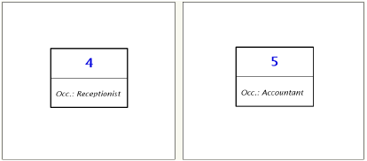
Use the Data Tag tool to add tags that display the data associated with drawing objects. This data can be general Parâmetros (such as height), record fields (such as a model number), or IFC data. You can also use the tool to add simple labels that are not linked to any object, such as a date stamp.
A large number of data tags are provided in the Vectorworks resource libraries. To display different data or tag different types of objects, create a custom tag.
The following modes are available.

Mode |
Descrição |
|---|---|
Active Tag Def |
Opens the Resource Selector to select a resource for tagging; double-click a resource to activate it |
Label |
Places a tag that is not linked to any drawing object |
Select Single Object |
When you click on an eligible object, places a tag that is linked to the object |
Select Eligible Objects |
Highlights all eligible objects that are selectable in the current layer or in the current viewport’s annotations; click one object to tag them all |
Towards Target Object |
If the active tag has a leader, the first click places the tag, and the second click specifies the target object |
Towards Data Tag |
If the active tag has a leader, the first click specifies the target object, and the second click places the tag |
Preferences |
Sets the preferences for the data tag object |
To add tags:
1 Click the tool, and then click Active Tag Def on the Tool bar. From the Resource Selector, locate the desired resource, and double-click to activate it.
Vectorworks library files that name specific types of objects (such as Space Label.vwx) contain tags that are designed to be attached to that type of object and to display specific data from the object. The other files contain tags that do not link to an object; these are used as labels only.
To create a custom tag, select an existing tag or tag resource to use as a starting point. Edit the Parâmetros, geometry, and data as described in Creating Data Tag Styles.
2 From the Tool bar, click the desired modes for placing the tag and leader, if applicable.
• If a simple label tag (such as a date stamp) is active, select Label mode.
• If an object-linked tag (such as a space label) is active, select either Select Single Object or Select Eligible Objects mode.
3 If the active tag is not appropriate for the selected mode or for the available drawing objects, an alert displays (for example, if you selected a door tag, but there are no doors in the current view or layer). Select a different tag or mode, or adjust what can be seen and selected in the current view.
4 Place the tag as follows:
• Label mode: If the tag has no leader, simply click to place the tag. Otherwise, click twice, to place the tag and the end of the leader line separately.
• Select Single Object mode: An eligible object is highlighted when the cursor is over it. If the tag has no leader, highlight the object to be tagged, and click to place the tag. Otherwise, click twice, to place the tag and leader line separately.
• Select Eligible Objects mode: All eligible objects are highlighted automatically. Click any one of the objects to tag all of them.

The data tag is placed in the appropriate plane, depending on where the tool is used.
• Viewport in an annotation context: annotation plane
• Design layer in Top/Plan view: layer plane
• Design layer in a 3D view: active plane
~~~~~~~~~~~~~~~~~~~~~~~~~
 Creating
Data Tag Styles
Creating
Data Tag StylesCommand |
Path |
|---|---|
Create Plug-In Style |
• Tools • Context menu |
The Vectorworks resource libraries provide many commonly used tags, such as window and door type IDs and date stamps. If you need a tag for a different type of object (such as columns), or to display different data (such as window dimensions), create a custom data tag style.
To create a data tag style:
1 Do one of the following:
• From the Resource Manager, select an existing data tag resource in the active file to use as a starting point. Right-click on the resource and select Edit from the context menu.
• Select an existing data tag in the drawing to use as a starting point. From the Object Info palette, select Convert to Unstyled from the Style list. Select the Create Plug-in Style command, or right-click on the tag and select New Plug-in Style from Unstyled Plug-in from the context menu. From the Create Symbol dialog box, select the destination folder for the data tag style.
The Data Tag Style dialog box opens.
► Clique para exibir/ocultar parâmetros
2 Enter the desired Parâmetros for the data tag. For each Parâmetro, specify whether it is to be set by style, or by instance. Style Parâmetros have a fixed value established by the style; instance Parâmetros can be set independently for each instance of the object in the drawing (see Concept: Plug-in Object Styles).
3 Click Edit Tag Layout.
In the tag editing window, draw the geometry of the tag in page units using any planar graphic tools. The origin (0,0) point is always the primary attachment point for a leader line, if used. To define an alternate attachment point, add a 2D locus to the geometry, and enable Allow Multiple Attachment Points in the Data Tag Style dialog box.
4 Use the Text tool to add static and/or dynamic text objects to the tag. From the Object Info palette, specify the appearance of the text; see Formatando Textos for more information about the options available.
• Static text simply displays the text object on each tag.
• Dynamic text displays data from the tagged object (for example, the width of the window) on each tag, in place of the text object. To create dynamic text, select the text object and click Use Dynamic Text from the Object Info palette. Then click Define Tag Field to open the Define Tag Field dialog box.
► Clique para exibir/ocultar parâmetros
5 When you are done editing the geometry and text fields on the tag, click Exit Tag Layout Edit. The new style is added to the Resource Manager for the current file and is now available for use with the Data Tag tool.

~~~~~~~~~~~~~~~~~~~~~~~~~
 Editing
Data Tags
Editing
Data TagsOnce a data tag is in the drawing, you might want to replace the tag with a different one, or edit the tag settings or data. These changes affect only the selected tag and its linked object, if applicable. To change all data tags of a certain style, see Editing Plug-in Object Styles.
To replace a data tag:
1 With the tag selected, select Replace from the Style list on the Object Info palette.
2 From the Resource Selector, locate the desired resource, and double-click to activate it.
3 Click OK to replace the tag. If the tag is linked to an object for which the selected replacement is not suitable, an alert displays.
To edit a data tag’s settings or layout:
1 With the tag selected, click Settings from the Object Info palette.
The Data Tag Settings dialog box opens.
2 The settings are very similar to those for Creating Data Tag Styles, except that Parâmetros that are set by style are not editable. If you click Convert to Unstyled to remove the style from the tag, all Parâmetros are editable. Edit the Parâmetros as desired.
3 If the tag layout can be edited by instance, there are three ways to access the tag editing window:
• Click Edit Tag Layout on the Data Tag Settings dialog box.
• Click Edit Tag Layout on the Object Info palette.
• Right-click on the tag and select Edit Tag Layout from the context menu.
Command |
Path |
|---|---|
Edit Tag Data |
Context menu |
Edit an existing tag to change the data displayed on it. For example, you might change the width of a window, or renumber the incrementally numbered tags on a set of parking spaces. When you change data that is being displayed from a linked object’s record (such as window width), both the tag and the object are updated. Alternatively, if you edit the linked object directly, the data tag automatically updates to reflect the change.
To edit tag data:
1 Right-click on the tag and select the command. Alternatively, select the object and click Edit Tag Data from the Object Info palette.
The Edit Tag Data dialog box opens.
2 Edit the fields in the data tag as needed. Note that any Parâmetro or record data that is controlled by object style (as opposed to by instance) is not editable. In addition, a “calculated field” that contains multiple data fields from a record (for example, color and model number) is not editable.
3 To renumber auto-numbered tags, click Manage.
The Manage Sequence dialog box opens.
► Clique para exibir/ocultar parâmetros
By default, when you double-click on a data tag object, a dialog box displays, to select whether to edit the tag data or layout. To improve your workflow, skip the dialog box and always edit either the data or layout.
To set a double-click editing shortcut:
1 Right-click on a data tag in the drawing and select Edit from the context menu.
The Choose Component dialog box displays.
2 From the Double Click list, select whether a double-click will open the Edit Tag Data dialog box or the tag layout editing window.
~~~~~~~~~~~~~~~~~~~~~~~~~
 Welding Symbols
Vectorworks Design Series products contain a comprehensive collection of welding symbols. All symbols are placed as point objects.

~~~~~~~~~~~~~~~~~~~~~~~~~
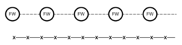
 Fillet Welding Symbol
Mode |
Tool |
Tool set |
|---|---|---|
Modes for The Symbol Insertion Tool |
Welding Sym-Fillet
|
Dims/Notes |
Multiple welding tools share the same position on the tool set. Click and hold the mouse on the visible tool to open the Ferramentas Pop-out list and select the desired tool.
To insert a fillet welding symbol:
1 Click the tool and mode.
2 Click to place the object in the drawing, and click again to set the rotation. The first time you use the tool in a file, a properties dialog box opens. Set the default properties. The properties can be edited from the Object Info palette.
3 Once the object has been placed, its marker can be selected from the Attributes palette (see Marker Attributes).

► Clique para exibir/ocultar parâmetros
~~~~~~~~~~~~~~~~~~~~~~~~~
 Groove Welding
Symbol
Groove Welding
Symbol Mode |
Tool |
Tool set |
|---|---|---|
Modes for The Symbol Insertion Tool |
Welding Sym-Groove
|
Dims/Notes |
Multiple welding tools share the same position on the tool set. Click and hold the mouse on the visible tool to open the Ferramentas Pop-out list and select the desired tool.
To insert a groove welding symbol:
1 Click the tool and mode.
2 Click to place the object in the drawing, and click again to set the rotation. The first time you use the tool in a file, a properties dialog box opens. Set the default properties. The properties can be edited from the Object Info palette.
3 Once the object has been placed, its marker can be selected from the Attributes palette (see Marker Attributes).

► Clique para exibir/ocultar parâmetros
~~~~~~~~~~~~~~~~~~~~~~~~~
 Flange Welding Symbol
 Mode |
Tool |
Tool set |
|---|---|---|
Modes for The Symbol Insertion Tool |
Welding Sym-Flange
|
Dims/Notes |
Multiple welding tools share the same position on the tool set. Click and hold the mouse on the visible tool to open the Ferramentas Pop-out list and select the desired tool.
To insert a flange welding symbol:
1 Click the tool and mode.
2 Click to place the object in the drawing, and click again to set the rotation. The first time you use the tool in a file, a properties dialog box opens. Set the default properties. The properties can be edited from the Object Info palette.
3 Once the object has been placed, its marker can be selected from the Attributes palette (see Marker Attributes).

► Clique para exibir/ocultar parâmetros
~~~~~~~~~~~~~~~~~~~~~~~~~
 Miscellaneous Welding Symbols
 Mode |
Tool |
Tool set |
|---|---|---|
Modes for The Symbol Insertion Tool |
|
Dims/Notes |
Multiple welding tools share the same position on the tool set. Click and hold the mouse on the visible tool to open the Ferramentas Pop-out list and select the desired tool.
To insert a miscellaneous welding symbol:
1 Click the tool and mode.
2 Click to place the object in the drawing, and click again to set the rotation. The first time you use the tool in a file, a properties dialog box opens. Set the default properties. The properties can be edited from the Object Info palette.
3 Once the object has been placed, its marker can be selected from the Attributes palette (see Marker Attributes).

► Clique para exibir/ocultar parâmetros
~~~~~~~~~~~~~~~~~~~~~~~~~
 Slot-Plug Welding Symbol
 Mode |
Tool |
Tool set |
|---|---|---|
Modes for The Symbol Insertion Tool |
Welding Sym-Slot Plug
|
Dims/Notes |
Multiple welding tools share the same position on the tool set. Click and hold the mouse on the visible tool to open the Ferramentas Pop-out list and select the desired tool.
To insert a slot-plug welding symbol:
1 Click the tool and mode.
2 Click to place the object in the drawing, and click again to set the rotation. The first time you use the tool in a file, a properties dialog box opens. Set the default properties. The properties can be edited from the Object Info palette.
3 Once the object has been placed, its marker can be selected from the Attributes palette (see Marker Attributes).

► Clique para exibir/ocultar parâmetros
~~~~~~~~~~~~~~~~~~~~~~~~~
 Editing
the Welding Symbol Arrow Segment
Editing
the Welding Symbol Arrow Segment The arrow segment of each welding symbol has two control points for adjusting the segment position.

To move the control points of an arrow segment:
1 Select the welding symbol to edit.
2 Click and hold the leader end control point.
3 Drag the leader end control point to the new location and click to set.

4 Click and hold the leader shoulder control point.
5 Drag the leader shoulder control point to the new location and click to set.

 Creating Stipple Objects
Mode |
Tool |
Tool set |
|---|---|---|
Modes for the Polyline Tool |
Stipple
|
Dims/Notes |
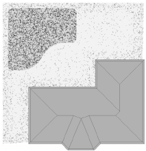
The Stipple tool creates a random pattern (different shapes, sizes, and, optionally, colors) within a defined boundary, which resembles a hand-drawn shaded effect. To create a stipple object, either use the Stipple tool, or draw a polyline and then run the Create Objects from Shapes command (see Creating Objects from Shapes).
To create a stipple object:
1 Click the tool and mode, and then click Preferences to set the default Stipple tool Parâmetros.
The Define Stipple Pattern dialog box opens. Up to two different shapes can be specified to define the stipple pattern.
► Clique para exibir/ocultar parâmetros
Both the Color Stipple Shapes and Fade Stipple from Edge options are processor-intensive actions and can significantly increase stipple regeneration time.
2 Click to set the object’s start point.
3 Click to set the end of the segment and the beginning of the next. Continue drawing segments in this manner until the object is complete.
4 Click a second time at the start point to complete a closed polyline object, or double-click to complete an open polyline object.
To edit the Parâmetros for a stipple object, click the Stipple Settings button from the Shape tab of the Object Info palette (the Parâmetros are described in Creating Stipple Objects).
To modify default stipple settings, click the Preferences button on the Tool bar.
To reshape a stipple object, double-click it to activate the Reshape tool. Select the object handles to reshape the stipple object boundary. For more information, see Remodelando Objetos.
Once a stipple is set to the desired appearance, you can save the pattern as a symbol for future use. When you select the stipple from the Resource Manager, all the settings are preset, and you can draw a new shape with that stipple pattern.
To save a stipple pattern:
1 Select a stipple object.
2 From the Object Info palette, click Save Stipple.
The Enter Text dialog box opens.
3 Enter a unique name.
The stipple pattern is saved as a symbol in the Stipples folder, in the active file.
4 To use a saved stipple pattern, double-click it from the Resource Manager, click a drawing mode from the Tool bar, and draw the new stipple object.
For more information on the Polyline tool modes, see Creating Polylines.
 Creating
Repetitive Unit Details
Creating
Repetitive Unit DetailsMode |
Tool |
Tool set |
|---|---|---|
Modes for the Polyline Tool |
Repetitive Unit
|
Detailing |
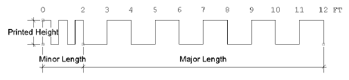
The Repetitive Unit tool draws world-scale symbols along a path, creating repetitive elements such as masonry units, shingles, and siding. To create repetitive unit details, either use the Repetitive Unit tool, or draw a polyline and then select the Create Objects from Shapes command (see Creating Objects from Shapes).
To draw repetitive unit details:
1 Click the tool and mode, and then click Preferences to select the detail symbol. The detail symbol can also be specified after creation.
2 Click to set the object’s start point.
3 Click to set the end of the segment and the beginning of the next. Continue drawing segments in this manner until the object is complete.
4 Click a second time at the start point to complete a closed polyline object, or double-click to complete an open polyline object.

Each unit is always drawn in its entirety; the last unit is not clipped, even if it exceeds the path drawn. The repetitive unit offset path is drawn in the object’s assigned pen style (the path always has a fill style of None).
The Repetitive Unit tool can create lines with custom symbols made from text and/or shapes. The Pitch determines the spacing; set the pen attributes from the Attributes palette.
The repetitive unit Parâmetros can be edited from the Object Info palette.
► Clique para exibir/ocultar parâmetros
Create a plug-in symbol from a repetitive unit object (see Criando Definições de Símbolos) with Convert to Plug-in Object selected. Activate the symbol in the Resource Manager to draw the repetitive unit with the saved symbol Parâmetros.