
Record formats can store a wide range of data about an object or symbol, such as material cost, part number, and area. Records attached to an object or symbol definition become a permanent part of it, remaining with the object or symbol even when it is imported or cut and pasted into another drawing. Several record formats can be attached to a single object or symbol, and record values can be individually changed for each object or symbol instance to which the record is attached.
In the Vectorworks Design Series products, you can link record formats to an external database for automated, two-way communication. See Database Connectivity.
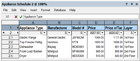
Reports and schedules are worksheets that provide data about the objects in a project file.
• All Vectorworks users can create reports, which allow you to select record data that is attached to objects in a drawing (such as manufacturer, size, and price) and create a worksheet based on the data. You can either create a new worksheet or append database rows to an existing worksheet.
• If Vectorworks Design Series is installed, several drawing elements (doors, plants, and lighting devices, for example) have predefined data that is automatically attached to them as they are created. Preformatted reports are available for this data.
Reports and schedules are easier and faster to create than custom worksheets, but they may not provide the exact information you want. If you need more specialized functions or calculations, either start with a report and customize it, or create a worksheet from scratch. See Worksheets.
~~~~~~~~~~~~~~~~~~~~~~~~~
Create record formats to add data to drawing objects, which can then be used in reports to provide information about the project. For example, for a hotel project, you might create a format that includes the model number, price, and location of different items of furniture. After you attach the appropriate data to the furniture objects, you could create a report that shows the number of sofas you need on each floor of the hotel.
To create a new record format:
1 From the Resource Manager, click New Resource, select Record Format, and then click Create. Alternatively, from the Resource Manager, select Record Formats from the list of resource types on the tool bar, and click New Record Format.
The Create Record Format dialog box opens.
► Clique para exibir/ocultar parâmetros.
2 Enter the Name of the record format.
3 Click New.
The Edit Field dialog box opens.
► Clique para exibir/ocultar parâmetros.
4 Set the parameters and click OK to return to the Create Record Format dialog box.
5 Repeat steps 3 and 4 to enter as many additional fields as needed.
~~~~~~~~~~~~~~~~~~~~~~~~~
Once a record format has been created, you can attach it to any object, symbol instance, or symbol definition in the same drawing file. If you attach a record format to a symbol definition, the record format will be automatically attached each time you place one of those symbols in the drawing.
Use the Data tab of the Object Info palette to add appropriate data to drawing items that have record formats, such as model number, price, and location. See Editing Object Data.
To attach record formats to a symbol instance or object in the drawing:
1 Select the item.
2 Do one of the following:
• From the Data tab on the Object Info palette, click Attach Record to display the Resource Selector. Select the desired record format to apply it.
• From the Resource Manager, right-click the desired record format, and select Apply from the context menu.
Alternatively, double-click the record format resource, or drag the record format resource onto the symbol instance or object to apply it.
To attach record formats to all existing and future symbols placed from that definition:
1 From the Resource Manager, right-click the symbol definition, and select Attach Record from the context menu.
The Attach Record dialog box opens.
2 Click the Attach column of each record to attach to the symbol definition.
3 To change the default values of the fields associated with the record format, select the record and click Edit Values. Change the default values as needed.
Existing symbol instances, as well as any future symbols placed from the symbol definition, have the record format and default values attached.
Another way to attach record formats to a symbol definition is to edit the definition. The attached record is included each time the symbol is placed in the drawing or imported into another drawing. Symbol instances already present in the drawing are not affected.
To attach record formats by editing the symbol definition:
1 From the Resource Manager, right-click the symbol definition, and select Edit 2D Components from the context menu.
2 From the Edit Symbol window, deselect all items by clicking in an empty area.
3 From the Object Info palette, click the Data tab.
When no items are selected, the Data tab displays “Symbol Definition” and the name of the symbol at the top.
4 Click Attach Record to display the Resource Selector. Select the desired record format to attach it. You can attach multiple records to the same symbol definition.
5 Edit the default values that display for the symbol definition, if necessary. These changes affect this symbol definition only, without changing the record format resource; see Editing Default Record Values for a Symbol Definition.
6 Click Exit Symbol at the top right of the Edit Symbol window.
Command |
Path |
|---|---|
Attach Record |
Tools > Records |
To attach a record to all of the symbol definitions in a specified symbol folder:
1 Select the command.
The Attach Record dialog box opens.
2 From the Symbol Folder list, select the criteria for attaching a record.
• Select None to attach the record to the symbol definitions at the root of the symbol library (symbol definitions not in any folder).
• Select All to attach the record format to all of the symbol definitions in the file’s symbol library.
• Select a symbol folder to change all of the symbol definitions in that folder and any subfolders.
3 From the Record Format list, select a record format to be attached to the selected symbol definitions.
4 Click OK.
A message displays the number of symbol definitions affected.
Symbol instances already present in the drawing are not affected.
To quickly verify that a record has been attached to the symbol library, create a report. See Creating Reports.
~~~~~~~~~~~~~~~~~~~~~~~~~
Use the Data tab on the Object Info palette to edit the record formats and data attached to specific drawing objects.
• When one or more objects are selected, this information applies to the selected objects only.
• If no objects are selected, “Document Record Format Defaults” displays at the top of the Data tab. Edits to the fields change the default values displayed when the record is first attached to a drawing object. No existing objects are affected.
To edit object data:
1 Select one or more objects.
2 Select the Data tab from the Object Info palette. Data information for the selected objects displays; record formats are listed above any attached IFC data (Vectorworks Design Series required). If necessary, you can resize the record format and record field lists by dragging the resize control below the Detach button.
► Clique para exibir/ocultar parâmetros.
3 From the Record Formats list, select a record to display the fields and current values associated with it.
4 Edit the record fields as needed. If you are using a database and the database connection is set to be Read Only, the fields are not editable; edit the database directly.
~~~~~~~~~~~~~~~~~~~~~~~~~
Edit the record format resource directly to change the record fields or default values for all objects or symbols to which you attach the record format in the future. Existing objects to which the record format is already attached are not affected.
To edit the fields and default values of a record format:
1 From the Resource Manager, right-click on the record format, and select Edit from the context menu.
The Edit Record Format dialog box opens.
2 Add, edit, or remove fields as described in Creating Record Formats.
You can change the default values of a record attached to a symbol while editing the symbol definition (see Editando Definições de Símbolo). This does not change the record format resource; if other symbols or objects have the record attached, they are not affected. It does change the default record values for future symbol instances.
To change the default field values of a symbol definition’s record format:
1 From the Resource Manager, right-click on the symbol definition, and select Edit 2D Components from the context menu.
2 From the Edit Symbol window, deselect all items by clicking in an empty area.
3 From the Object Info palette, click the Data tab.
When no items are selected, the Data tab displays “Symbol Definition” and the name of the symbol at the top.
4 From the Record Formats list, select the record format, and then enter default values in the fields that display.
5 Click Exit Symbol at the top right of the drawing window to return to the drawing.
Command |
Path |
|---|---|
Change One Field |
Tools > Records |
This command changes a specified field default value for a selected record format attached to all symbol definitions in a specified folder. Existing symbol instances in the drawing are not affected.
To change one record format field:
1 Select the command.
The Change One Field dialog box opens.
2 From the Symbol Folder list, select None, All, or a symbol folder, if any.
• Select None to attach the record to the symbol definitions at the root of the symbol library (symbol definitions not in any folder).
• Select All to attach the record format to all of the symbol definitions in the file’s symbol library.
• Select a symbol folder to change all of the symbol definitions in that folder and any subfolders.
3 From the Record Format list, select the record format.
The Field Name selections depend on the record format selected.
4 Select the Field Name to change.
5 Enter the New Value.
6 Click OK.
Confirm the operation and the number of symbol definitions affected.
Command |
Path |
|---|---|
Change All Fields |
Tools > Records |
This command changes several or all default field values for a selected record format attached to symbol definitions. Existing symbol instances in the drawing are not affected.
To change several or all record format fields:
1 Select the command.
The Change All Fields dialog box opens.
2 From the Symbol Folder list, select None, All, or a symbol folder, if any.
• Select None to attach the record to the symbol definitions at the root of the symbol library (symbol definitions not in any folder).
• Select All to attach the record format to all of the symbol definitions in the file’s symbol library.
• Select a symbol folder to change all of the symbol definitions in that folder and any subfolders.
3 From the Record Format list, select the record format.
4 Click OK.
The Change Fields dialog box opens. The title bar displays the name of the record being edited.
5 Select the field names to change and enter the new information.
All of the field names of the record format are listed. If the record file has more than 16 fields, click Next to view the remaining fields in the record.
6 After making the desired changes, click OK.
Confirm the operation and the number of symbol definitions affected.
To detach record formats for a single symbol instance or object in the drawing:
1 Select the object.
2 From the Data tab on the Object Info palette, click Detach.
To detach record formats from symbols that will be added in the future:
1 From the Resource Manager, right-click on the symbol definition, and select Edit 2D Components from the context menu.
2 From the Edit Symbol window, deselect all items by clicking in an empty area.
3 From the Object Info palette, click the Data tab.
When no items are selected, the Data tab displays “Symbol Definition” and the name of the symbol at the top.
4 Click Detach.
5 Click Exit Symbol at the top right of the Edit Symbol window.
The detached record is no longer included with the symbol each time the symbol is placed in the drawing or imported into another drawing. Existing symbol instances in the drawing are not affected.
Command |
Path |
|---|---|
Detach Record |
Tools > Records |
To detach a record from all of the symbol definitions in a specified symbol folder:
1 Select the command.
The Detach Record dialog box opens.
2 From the Symbol Folder list, select one of the following options.
• Select None to detach the record from the symbol definition at the root of the symbol library (symbol definitions not in any folder).
• Select a symbol folder to change all of the symbol definitions in that folder and any subfolders.
• Select All to detach the record format from all of the symbol definitions in the file’s symbol library.
3 From the Record Format list, select one of the record formats defined in the current file to detach from the symbol library.
4 Click OK.
A message displays the number of symbol definitions affected.
Command |
Path |
|---|---|
Split Record Format |
Tools > Records |
Record fields and associated data from one record format can be transferred to another new record format. This is useful, for example, when importing GIS data (Vectorworks Design Series required) with a significant number of record fields that may need to be reorganized.
To split a record format into two formats:
1 At least one record format must be present in the file. Select the command.
The Split Record Format dialog box opens. Select the record format to edit from the Source Record Format list.
► Clique para exibir/ocultar parâmetros.
2 Click to place a check mark next to the record fields that should be split from the selected format.
3 Enter a name for the new record format; it will contain the split record fields.
The indicated record fields (and associated data) are removed from the source record format and placed in the new record format, in record format order. All objects which had the original record format attached now have both the original record format and the new record format attached. No record fields and data are lost during this operation.
Command |
Path |
|---|---|
Merge Record Formats |
Tools > Records |
The record fields, and associated data, from two record formats can be merged into one record format.
To merge two record formats:
1 At least two record formats must be present in the file. Select the command.
The Merge Record Formats dialog box opens.
2 Select the format to be merged from the Merge Record Format list.
The record fields from this record format will be merged, and this record format will be deleted.
3 Select the record format to receive the record fields that are merged.
The merged record fields are appended to the end of the receiving format’s record fields, in record format order. If there is a naming conflict and there are two fields with the same name, the transferred field name begins with an “_” (underscore). Any objects which had the first format attached now have the merged record attached instead. Any objects which already had the merged record attached now have the additional record fields included. The first Merge Record Format is deleted.
~~~~~~~~~~~~~~~~~~~~~~~~~
Command |
Path |
|---|---|
Link Text to Record |
Tools > Records |
The Link Text to Record command links the text within a symbol definition to a field of the attached record. This is particularly useful for labeling symbols in a drawing with unique information, such as a part list number or price. To use this command, symbols and record formats must already exist in the drawing file.
To link text to records within a symbol definition:
1 Edit the 2D symbol definition as described in Editando Definições de Símbolo.
2 In the Edit Symbol window with nothing selected, create a line or block of text.
Format the text with the desired font and style. The actual text is not important at this point. If desired, create and assign a class to the text.
3 Position the text in the exact location where the record data value is to display.
4 With the text still selected, select the command.
The Choose Field dialog box opens.
5 Select the record format that contains the data you want to link from the Formats list.
6 Select the field of the selected record to associate with the text from the Fields list.
7 Click OK.
The text object is added to the symbol definition, as well as all existing instances on the drawing. The default value of the selected field replaces the “dummy” text.
8 Click Exit Symbol at the top right corner of the drawing window to return to the drawing.
When you place the symbol on the drawing, the field information for this instance of the symbol displays. To update it, select the symbol and then edit the field from the Data tab of the Object Info palette.

~~~~~~~~~~~~~~~~~~~~~~~~~
 Modifying Objects
by Record Value
Modifying Objects
by Record ValueCommand |
Path |
|---|---|
Modify by Record |
Tools > Records |
This command modifies the color, size, or height of objects in a drawing based on the numeric value of a particular record field attached to the selected items. This can be useful for analyzing and comparing objects in a drawing.
To modify objects by record value:
Select the command.
The Modify by Record Value dialog box opens; set the parameters.
► Clique para exibir/ocultar parâmetros.

Command |
Path |
|---|---|
Modify by Record |
Tools > Records |
If you have saved settings to use with the Modify by Record command, the Manage button can rename or delete these saved settings when needed.
To manage saved settings for the Modify by Record command:
1 Select the command.
The Modify by Record Value dialog box opens.
2 Click Manage.
The Manage Saved Sets dialog box opens. Select the set to change.
► Clique para exibir/ocultar parâmetros.
~~~~~~~~~~~~~~~~~~~~~~~~~
Command |
Workspace: Path |
|---|---|
Create Report |
• Fundamentals, Architect, Landmark: Tools > Reports • Spotlight: Spotlight > Reports |
The Create Report command allows you to select a group of objects from a drawing and then create a worksheet based on data that is associated with the objects (such as a price, or the object’s class). You can either create a new report or append database rows to an existing report. For more information about how to attach data to objects, see Attaching Record Formats to Symbols and Objects.
This method of Creating Worksheets may be preferable to creating a worksheet from scratch, if you are not comfortable directly editing criteria and worksheet functions.
|
Click here for a video tip about this topic (internet access required). |
To create a report from objects in a drawing:
1 Select the command.
Alternatively, from an existing worksheet, right-click a spreadsheet row number and select Create Report, or right-click a database row number and select Edit Report. The Create Report (or Edit Report) dialog box opens.
► Clique para exibir/ocultar parâmetros.
2 Specify the report criteria and columns, and click OK to create the report.
3 If you opted to place the report on the drawing, click in the drawing to place it. Otherwise, the worksheet opens automatically. The top row of the worksheet contains a title for each column selected. Next is a database header row (indicated by a diamond next to the row number) that contains sub-row totals for each column. Beneath the header row are sub-rows for each object or symbol in the drawing that matches the report criteria.
4 To append additional reports to the worksheet, repeat step 1 and select the Append to existing report option before you click OK to create the report.
5 To edit the report data, right-click a database row number and select Edit Report.
6 Once all the data is added, edit the worksheet. For example, add rows or columns, change the text format, or add color.
~~~~~~~~~~~~~~~~~~~~~~~~~
 Using
Preformatted Reports
Using
Preformatted ReportsCommand |
Workspace: Path |
|---|---|
Create Report |
• Architect and Landmark: Tools > Reports • Spotlight: Spotlight > Reports |
Several drawing elements in the Vectorworks Design Series products (doors, plants, and lighting devices, for example) have predefined data that is automatically attached to them as they are created. Preformatted reports are available for this data. The reports can be created any time; as objects are added to the drawing, recalculate the worksheet to update the results.
To choose a preformatted report:
1 Select the command.
The Create Report dialog box opens.
The Enable Vectorworks Libraries option must be selected in the Vectorworks preferences to see the preformatted reports. See Aba Seção.
2 From the Type field, select Preformatted Report.
3 Select one of the reports to create; also select Place report on drawing to add the worksheet to the drawing area.
4 Click OK to create the selected report.
If the selected report already exists in the file, a warning dialog box opens. Select whether to replace or rename the new report.
5 If you opted to place the report on the drawing, click in the drawing to place it. Otherwise, the worksheet opens automatically.
6 If you customize the report, you can save it and use it again. From the Resource Manager, import the worksheet resource (renamed with a custom name) into a file. Then place the file in your [User]\Libraries\Defaults\Reports_Schedules folder. This makes your customized worksheet available for selection in the Create Report dialog box. See Creating Custom Resource Libraries.
You can also import the worksheets into your file directly from the Vectorworks resource libraries.
To import a preformatted report:
1 From the Resource Manager’s file browser pane, open Vectorworks Libraries/Defaults/Reports_Schedules, and select a file.
2 From the resource viewer pane, right-click a worksheet and select Import from the context menu. Alternatively, drag the resource to the active file in the file browser pane. See Importing Resources.
~~~~~~~~~~~~~~~~~~~~~~~~~
 Creating a
Room Finish Legend
Creating a
Room Finish LegendCommand |
Path |
|---|---|
Create Rm Finish Legend |
Tools > Reports |
There can be dozens of room finishes assigned within a project file. To obtain a detailed report of all room finish data, first generate a room finish schedule as described in Using Preformatted Reports. Then generate a detailed legend showing a full description of the finishes using the Create Rm Finish Legend command. This command can only be used after room finishes have been assigned to space objects.
To generate a room finish legend:
1 Select the command.
The Create Room Finish Legend dialog box opens.
► Clique para exibir/ocultar parâmetros.
2 Select whether the legend should be displayed as a text block or as a worksheet. See Criando Blocos de Texto and Creating Worksheets.
Display Method |
Description |
|---|---|
Text block |
Define the area for the legend to occupy. Click to set the top left corner of the text block, and then click to set the bottom right of the text block. The text legend is generated within the defined rectangle. |
Worksheet |
The worksheet is created with the legend information. If the Place worksheet in document option is selected, click the drawing to set the top left corner of the worksheet. |
~~~~~~~~~~~~~~~~~~~~~~~~~
