Projeto
Básico de Eventos
Projeto
Básico de EventosProjetando Eventos
Projeto
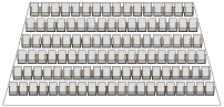
Básico de EventosThe basic event design suite available in Vectorworks Spotlight contains automated tools to facilitate setting up a complete room layout for an event such as a banquet, presentation, or training session. Automatically create the room for the event, including the slab, walls, stage, steps, lectern, video screens, and seating. View the room setup in a rendered or plan view, and obtain a report on the total number of tables and chairs required for the event.
Vectorworks Spotlight also offers greatly expanded Event Design capabilities with all the features needed for concert and theatrical venues.
The event design suite uses objects to quickly and automatically create the room plan with only a few parameter settings required. However, due to the powerful nature of these objects, they can be specifically tailored through the Object Info palette to customize their appearance if needed.
~~~~~~~~~~~~~~~~~~~~~~~~~
 Creating the
Room for a Basic Event
Creating the
Room for a Basic EventCommand |
Path |
|---|---|
Create Room |
Event Design |
The first step of basic event design is usually creating the event room. Based on a simple 2D shape, the room and floor slab are created automatically according to specified parameters.
To create the room:
1 Create a closed 2D object (such as a rectangle, polyline, or polygon) to represent the room. The dimensions of the object should match the interior dimensions of the room to be created.
2 With the 2D object selected, select the command.
The Create Room dialog box opens. Specify the properties and attributes of the walls and the floor slab.
► Clique para exibir/ocultar parâmetros.

Wall and slab parameters can be edited in the Object Info palette; see Editing Walls and Criando Lajes.
When Moving Connected Walls with the Connected Walls mode of the Selection tool enabled, the adjoining walls and the slab change automatically to maintain the connection.
~~~~~~~~~~~~~~~~~~~~~~~~~
 Creating a
Basic Stage
Creating a
Basic StageCommand |
Path |
|---|---|
Create Stage |
Event Design |
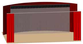
Many event rooms contain a stage for viewing presentations. Based on the Stage Deck and Stage Plug tools, a stage is automatically created according to specified parameters. The required number, size, and type of stage objects automatically fill the designated area. For more customizable options, see Inserting Stage Structures.
To create the stage area:
1 Create a closed 2D object (such as a rectangle, polyline, or polygon) to represent the stage. The dimensions of the object should match the dimensions of the stage to be created.
2 With the 2D object selected, select the command.
The Create Stage dialog box opens. Specify the stage properties and attributes.
► Clique para exibir/ocultar parâmetros.
If the area is rectangular, stage decks are inserted; otherwise, a combination of stage deck and/or stage plug objects are inserted.

Individual stage parameters can be edited in the Object Info palette; see Inserting a Stage Deck and Inserting a Stage Plug.
~~~~~~~~~~~~~~~~~~~~~~~~~
 Creating
Basic Stage Stairs
Creating
Basic Stage StairsCommand |
Path |
|---|---|
Create Stair |
Event Design |
Stairs or steps are usually required to provide access to the stage from the floor. The steps are automatically adjusted to meet the top of the stage. The basic stage stairs are based on the Stage Steps tool (see Inserting Stage Steps).
To add basic stage stairs:
1 Select the command.
The Create Stair dialog box opens.
► Clique para exibir/ocultar parâmetros.
2 Click once in the drawing to set the stair position. Click again to set the stair rotation.

Stair parameters can be edited in the Object Info palette; see Inserting Stage Steps.
~~~~~~~~~~~~~~~~~~~~~~~~~
 Creating a
Lectern
Creating a
LecternCommand |
Path |
|---|---|
Create Lectern |
Event Design |
After the stage and stairs have been added, a lectern can be quickly configured and placed. When placed on the stage, the lectern elevation is automatically adjusted to the top of the stage.
To add a lectern:
1 Select the command.
The Create Lectern dialog box opens.
► Clique para exibir/ocultar parâmetros.
2 Click once in the drawing to set the lectern position. Click again to set the lectern rotation.

~~~~~~~~~~~~~~~~~~~~~~~~~
 Creating a
Basic Video Screen
Creating a
Basic Video ScreenCommand |
Path |
|---|---|
Create Screen |
Event Design |
Video screens are often necessary at events and a basic screen can be quickly configured and placed as part of the basic event design setup; see Inserting Video Screen Objects for a suite of more robust tools.
To add a video screen object:
1 Select the command.
The Create Screen dialog box opens.
2 Select the type of video screen object to insert.
3 Click once in the drawing to set the video object position. Click again to set the object’s rotation.

Screen parameters can be edited in the Object Info palette; see Inserting Video Screen Objects.
~~~~~~~~~~~~~~~~~~~~~~~~~
 Creating a
Basic Seating Layout
Creating a
Basic Seating LayoutCommand |
Workspace: Path |
|---|---|
Create Seating Layout |
• Architect: AEC • Spotlight: Spotlight > Architectural |
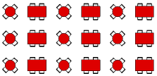
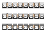
The Create Seating Layout command creates a seating layout object from one or more selected polygons, rectangles, rounded rectangles, ovals, arcs/circles, or polylines. Seating can consist of chairs, tables, or tables and chairs. Seating fills the objects in a user-defined arrangement with a “look-to” location defined by a control point. Seating layout objects can also be created by drawing a polyline and then selecting the Create Objects from Shapes command (see Creating Objects from Shapes). Along with the seating layout, a Seating Count worksheet is created.
The seating layout object is meant to provide a quick, preliminary seating plan. Vectorworks Spotlight users can use the Create Seating Section command to create a more detailed seating layout appropriate for final designs in professional event venues (see Creating Seating Sections). Seating layouts can be converted into seating sections for additional detailing by using the Create Seating Section command.
To create a basic seating layout object:
1 Create the shape defining the boundary of the seating area. Objects with one or more holes can be selected; seating will not be placed where a hole exists. Multiple shapes can be selected at one time (to create several seating sections, for example).
2 With the object selected, select the command.
The Create Seating Layout dialog box opens.
A seating layout can also be created by clicking the Seating Layout tool from the Furn/Fixtures tool set. Draw a polygon with the tool and complete the parameters, which are identical to those described in Editing the Basic Seating Layout.
► Clique para exibir/ocultar parâmetros.
3 A default symbol can be created to represent the seating; select Create a new seat symbol called and provide a symbol name. Alternatively, select an appropriate seating symbol from a library or the current file. In addition to seat symbols, table symbols and table and chair symbols can be used.
See Using Resources in Your Drawing for information on importing symbols.
4 Click OK to close the Create Seating Layout dialog box.
5 When prompted, click the focal point for the seating. All seats will face this point; table and chair symbols orient towards the point.
For concentric seat layouts, the distance of the seat focal point from the object determines the radius of the concentric layout. Click close to the object for a smaller radius.
The seating layout object and a Seating Count worksheet are created, with automatically calculated seat and table counts.
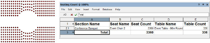
The Seating Count worksheet displays the number of seats and/or tables required for each seating layout section, as well as the total number of seats/tables needed for all sections. Nested symbols are counted in the worksheet, so tables and chairs are counted separately within a table and chair symbol. (If a symbol cannot be identified as a table or chair, it is counted as a chair.)
This worksheet functions only with a seating layout object. If you convert the seating layout to a seating section, the worksheet does not update.
~~~~~~~~~~~~~~~~~~~~~~~~~
 Editing the Basic Seating
Layout
Editing the Basic Seating
LayoutSeating layout parameters can be edited in the Object Info palette.
► Clique para exibir/ocultar parâmetros.
The seating layout can be reshaped with the Reshape tool to add, subtract, and change vertices. The seats are automatically adjusted to fit the new shape. More sophisticated editing operations, such as adding, clipping, intersecting and combining into surfaces can be performed on the seating layout path object by selecting Modify > Edit Seating Layout.
The seating section name and seating count text position can be adjusted by moving the control point. Adjust the text font and size of the label and seat numbers with the commands from the Text menu.

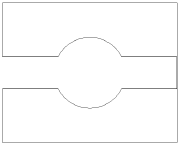
If the seating orientation requires adjustment, the seat control point can be moved to readjust the seating focal point. The control point is referenced relative to the center of the seating layout. If two imaginary axis lines were placed over the seating layout as shown in the diagram, placing the control point in line with the center of the axes would orient the seats directly toward the control point.

~~~~~~~~~~~~~~~~~~~~~~~~~
 Seating Symbol Specifications
The Create Seating Layout command in the Vectorworks Architect and Spotlight products and the Create Seating Section command in the Vectorworks Spotlight product use table and chair symbols that are available from the default content. It’s also possible to make your own table, chair, and nested table and chair symbols for use with these features (see Customizing Seating Symbols).
Symbols should be hybrid (2D/3D) so that they display properly in both 2D and 3D views. At a minimum, the symbol must contain a 2D representation.
Create the 2D view of the symbol using as few polygons and lines as possible. If possible, use a single polyline rather than individual line segments. The line weight of the symbol is also a consideration; the symbols need to stand out when printed. The outer perimeter of the symbol should have a line weight of at least 1/2 point (7 mils). Interior details should use a lighter line weight. The 2D representation should have a solid fill so that it obscures information under the symbol.
Keep the 3D symbol simple. It should be solid. The model should be accurately sized, but without minute details. These items can add significantly to the rendering time required, and are not necessary to distinguish among objects.
To create a table and chair symbol, create the chair and table symbols separately, and then create a symbol from the table and chair symbols, so that the table and chair symbols are nested symbols.
Attach the Event Planning Record to the symbol definition, with the Type field indicating whether the symbol is a table or chair. This allows the Seating Count worksheet to accurately count tables and chairs.
To attach the event planning record:
1 From the Resource Manager, select Vectorworks Libraries\Defaults\Event Planning\Seating\Seating.vwx. Drag the Event Planning Record to the active file to import it.
2 From the Resource Manager, right-click the symbol definition, and select Attach Record from the context menu.
The Attach Record dialog box opens.
3 Click the Attach column next to the Event Planning Record.
4 Select the Event Planning Record and click Edit Values. In the Type field, enter “Table” or “Chair.”
~~~~~~~~~~~~~~~~~~~~~~~~~
 Creating
Basic Event Views
Creating
Basic Event ViewsCommand |
Path |
|---|---|
Create Views |
Event Design |
Once the desired elements of the event have been added to the room, it is often necessary to create views of the room to show to the client. The Create Views command automatically creates two sheet layers that reflect basic views of the event layout: a 2D plan view and a rendered isometric view. The Plan View sheet layer displays the layout in a Top/Plan, Wireframe mode viewport, and includes the seating count worksheet. The Rendered View sheet layer displays the layout in an isometric viewport, rendered in OpenGL mode.
To create a 2D and basic 3D rendered view of the event layout:
1 Select the command.
2 The views are automatically created. The rendered viewport may require updating; with the viewport selected, click Update from the Object Info palette.

~~~~~~~~~~~~~~~~~~~~~~~~~
 Event Design
The Vectorworks Spotlight product offers tools and commands needed to design sophisticated concert and theatrical venues. You can create seating sections, stages, soft goods, and video and audio objects, in addition to designing complete lighting, hoist, and cable networks.
Vectorworks Spotlight also offers a Projeto Básico de Eventos suite appropriate for designing room layouts for events such as banquets, presentations, or training sessions.
~~~~~~~~~~~~~~~~~~~~~~~~~
 Creating Seating Sections
Command |
Path |
|---|---|
Create Seating Section |
Event Design |
Use the Create Seating Section command to create the final, detailed design for seating sections in a variety of configurations. You can create features such as rises and custom numbering plans, edit individual seats as needed to create exactly the arrangement you need, and then output the data to editable reports included with the software. Quick editing capabilities allow you to change specific elements of the plan without using the processor resources to redraw the entire seating section.
To quickly design preliminary seating layouts that can be converted into seating sections for final detailing, see Creating a Basic Seating Layout.
|
Click here for a video tip about this topic (internet access required). |
To create a seating section:
1 Select the objects (such as 2D shapes, seating layouts, multiple seating sections to combine, or multiple seating symbols) to create the seating section.
2 Select the command.
The settings are grouped into several panes of related parameters, which are listed on the left side of the dialog box; these parameters vary depending on whether a standard or curved seating type is selected. Select each pane and specify the seating section parameters.
These parameters can be edited for selected seating sections from the Object Info palette, as described in Editing Seating Sections.
Every pane of the Seating Section Settings dialog box displays a preview of the seating section with the current settings; the preview updates dynamically as the settings are edited.
► Clique para exibir/ocultar parâmetros.
► Clique para exibir/ocultar parâmetros.
► Clique para exibir/ocultar parâmetros.
► Clique para exibir/ocultar parâmetros.
If the seating section object is four-sided and all four corners are 90°, you can specify an angle for the seating within the boundary.
► Clique para exibir/ocultar parâmetros.
► Clique para exibir/ocultar parâmetros.
~~~~~~~~~~~~~~~~~~~~~~~~~
 Customizing
Seating Symbols
Customizing
Seating SymbolsIt is possible to customize the seating symbol attributes to create a new hybrid symbol definition for use in seating sections.
1 From the Arrangement pane of the Creating Seating Section dialog box, select a Seating Symbol to use as the basis for the customized symbol.
2 Click Customize Symbol to change the default appearance of the selected symbol if desired. This creates a new symbol definition that is added to the file’s resources.
The Customize Symbol dialog box opens.
► Clique para exibir/ocultar parâmetros.
 Editing
Seating Sections
Editing
Seating SectionsCommand |
Path |
|---|---|
Edit Boundary |
Context menu |
To change the boundary of the seating section:
1 Select the command.
The Object Editing Mode opens.
2 Edit the boundary vertices directly, and use other tools and commands including the Ferramenta Corte, the Ferramenta Aparar, and the commands for Editando Superfícies de Objetos.
Alternatively, use the Reshape tool to reshape the boundary (see Remodelando Objetos).
Some, but not all, parameters can be edited from both the Seating Section Settings dialog box and the Object Info palette for ease of access. The fields in the Object Info palette are named similarly (but not always identically) to those in the Seating Section Settings dialog box, and roughly reflect the order in which settings are entered in the dialog box. The seating section parameters are described in Creating Seating Sections. Only the parameters that are different are described here.
► Clique para exibir/ocultar parâmetros.
Command |
Path |
|---|---|
Edit Seating |
Context menu |
To make final custom edits to individual seats or sets of seats:
1 Right-click on the seating section and select the command.
Alternatively, double-click on the seating section object, or click Edit Seating from the Object Info palette.
2 The Object Editing Mode opens. You can add or delete seats, change the angle of individual seats, or change the size of the floor.
3 When you exit object editing mode, you are given the option to automatically reshape the bounding box to accommodate the edits.

Command |
Path |
|---|---|
Number Seats |
Context menu |
To custom renumber only selected seats within the seating section:
1 Right-click on the seating section and select the command.
The Number Seats dialog box opens.
2 Specify the new seat and row number parameters.
Object editing mode opens.
3 Select individual seats in the order you wish to number them, and then click in an empty part of the drawing to end numbering.
~~~~~~~~~~~~~~~~~~~~~~~~~
 Inserting
Soft Goods
Inserting
Soft Goods 
The Soft Goods tool is in the Event Design tool set (Spotlight and Braceworks workspaces) and the Detailing tool set (Designer workspace).
The Soft Goods tool inserts theater and event planning draperies such as curtains, borders, scrims, and pipe-and-drape assemblies. Soft goods objects are drawn along a path, so they can be straight, curved, or in any configuration for total flexibility; the path can be edited after placement. The 3D appearance of soft goods objects can be set for a realistic appearance, or display more schematically. The materials used to create the soft goods configuration can be included in a report for cost estimation (see Creating Reports). Text labels identify the components of the soft goods object.
|
Click here for a video tip about this topic (internet access required). |
There is an alternate way to create soft goods effects without the Soft Goods tool, which may be useful for users not using the Spotlight product.
|
Click here for a video tip about this topic (internet access required). |
~~~~~~~~~~~~~~~~~~~~~~~~~
 Inserting
Curtains and Borders
Inserting
Curtains and Borders Mode |
Tool |
Workspace: Tool set |
|---|---|---|
Modes for the Polyline Tool |
Soft Goods
|
• Spotlight: Event Design • Designer: Detailing |
The Soft Goods tool creates a curved or straight stage curtain or border. To draw a curtain, either use the Soft Goods tool, or create a polyline and then select the Create Objects from Shapes command (see Creating Objects from Shapes).
To insert a curtain or border:
1 Click the tool and the desired creation mode.
2 Click Preferences to specify the default Soft Goods tool parameters.
The Soft Goods Object Properties dialog box opens.
3 Select either Curtain or Border from the Function list, and specify any other default parameters for this session.
4 Click the desired creation mode for the soft goods object.
The Corner Vertex or Point on Arc modes are recommended. For more information on the polyline drawing modes, see Creating Polylines.
5 Click to set the soft goods object’s start point.
6 Click to set the end of the segment and the beginning of the next. Continue drawing segments in this manner until the curtain or border object is complete, and then double-click.
Once created, the soft goods object can be reshaped by double-clicking on it. The Reshape tool is automatically activated, to reshape the object directly in the drawing.
The curtain or border parameters can be edited from the Object Info palette. However, certain parameters are not available for borders.

► Clique para exibir/ocultar parâmetros.
~~~~~~~~~~~~~~~~~~~~~~~~~
 Inserting
Pipe-and-Drape Assemblies
Inserting
Pipe-and-Drape Assemblies Mode |
Tool |
Workspace: Tool set |
|---|---|---|
Modes for the Polyline Tool |
Soft Goods
|
• Spotlight: Event Design • Designer: Detailing |
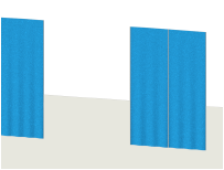
The Soft Goods tool creates pipe-and-drape assemblies typically used in event planning, such as when creating temporary booths in a convention center. To draw a pipe-and-drape assembly, either use the Soft Goods tool, or create a polyline and then select the Create Objects from Shapes command (see Creating Objects from Shapes).
1 Click the tool and the desired creation mode.
2 Click Preferences to specify the default Soft Goods tool parameters.
The Soft Goods Object Properties dialog box opens.
3 Select Pipe-and-Drape from the Function list, and specify any other default parameters for this session.
4 Click the desired creation mode for the soft goods object.
For more information on the polyline drawing modes, see Creating Polylines.
5 Click to set the soft goods object’s start point.
6 Click to set the end of the segment and the beginning of the next. Continue drawing segments in this manner until the pipe-and-drape assembly is complete, and then double-click.
Once created, the soft goods object can be edited by selecting the object, and then selecting Modify > Edit Soft Goods. Reshape the soft goods polyline with the Reshape tool; click Exit Profile to return to the drawing.
The pipe-and-drape assembly parameters can be edited from the Object Info palette.

► Clique para exibir/ocultar parâmetros.
To create an opening in the pipe-and-drape assembly, edit the vertex parameters from the Object Info palette. Select the vertex prior to the opening as described in Editing Vertex-Based Objects, and then click Hide Next Edge.
~~~~~~~~~~~~~~~~~~~~~~~~~
 Setting
Soft Goods 3D Display Options
Setting
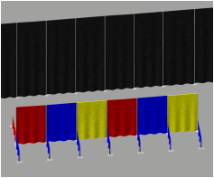
Soft Goods 3D Display Options Select a texture or color to display on the curtain, border, or pipe-and-drape assembly in 3D views. A curtain object can also be made to look like a scrim; pipe-and-drape assemblies can have alternating panel colors. The Vectorworks Spotlight product includes a number of sample textures, or you can create your own textures (see Creating Textures). The settings made here override any class settings made, if the soft goods object is assigned to a class; an alert dialog box opens if there is a conflict.
To set the 3D display options:
Select a curtain, border, or pipe-and-drape assembly. From the Object Info palette, click 3D Curtain Options. The 3D Curtain Options dialog box opens. Select the display option from the 3D Curtain Options list and then choose the formatting options.
► Clique para exibir/ocultar parâmetros.
~~~~~~~~~~~~~~~~~~~~~~~~~
 Formatting
Soft Goods Object Labels
Formatting
Soft Goods Object Labels A variety of soft goods object labels can be included on the drawing.
To select labels for display and format the text:
1 Select a soft goods object. From the Object Info palette, click Text Options.
The Text Options dialog box opens.
► Clique para exibir/ocultar parâmetros.
2 Specify the text label elements and formatting.
Once the label has been added to the drawing, it can be moved by clicking and dragging the label control point (unless Automatically Position Text is selected in the Text Options). Click Default Text Positions from the Object Info palette of a selected soft goods object to restore the text label to its original location.

~~~~~~~~~~~~~~~~~~~~~~~~~
 Creating
Barriers with the Rope and Stanchion Tool
Creating
Barriers with the Rope and Stanchion ToolMode |
Tool |
Tool set |
|---|---|---|
Modes for the Polyline Tool |
Rope and Stanchion
|
Event Design |
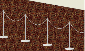
The Rope and Stanchion tool creates various types of barricades or roped-off areas for crowd control or for decorative purposes.
To insert a rope and stanchion barrier:
1 Click the tool and the desired creation mode.
2 Click to set the object’s start point.
3 Click to set the end of the segment and the beginning of the next. Continue drawing segments in this manner until the rope and stanchion object is complete, and then double-click.
The first time you use the tool in a file, a properties dialog box opens. Set the default properties.
Reshape the rope and stanchion polyline with the Reshape tool.
The rope and stanchion parameters can be edited from the Object Info palette.
► Clique para exibir/ocultar parâmetros.
~~~~~~~~~~~~~~~~~~~~~~~~~
 Formatting Rope and Stanchion
Labels
Formatting Rope and Stanchion
LabelsA variety of rope and stanchion object labels can be included on the drawing.
To select labels for display and format the text:
1 Select a rope and stanchion object. From the Object Info palette, click Text Options.
The Text Options dialog box opens.
► Clique para exibir/ocultar parâmetros.
2 Specify the text label elements and formatting.
Once the label has been added to the drawing, it can be moved by clicking and dragging the label control point (unless Automatically Position Text is selected in the Text Options). Click Default Text Positions from the Object Info palette of a selected rope and stanchion object to restore the text label to its original location.

~~~~~~~~~~~~~~~~~~~~~~~~~