Inserting
Video Screen ObjectsInserting
Video Screen Objects
Inserting
Video Screen ObjectsInserting
Video Screen ObjectsVideo screen objects, such as televisions, projectors, and screens, are often a required part of visualizing a room layout for event planning, and are occasionally needed for theater productions. The Vectorworks Spotlight product automatically helps with the calculations required for placement, image size, and viewing area; it can also display a “glowing” image on the screen for a realistic look. The video objects can be labeled with calculated information, and certain objects display the optimum viewing area.
~~~~~~~~~~~~~~~~~~~~~~~~~
 Inserting
a Television Object
Inserting
a Television Object Mode |
Tool |
Tool set |
|---|---|---|
Modes for The Symbol Insertion Tool |
Television
|
Event Design |
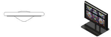
The television object simulates CRT and flat screen televisions.

To insert a television:
1 Click the tool and the desired insertion modes.
2 Click to place the object in the drawing, and click again to set the rotation.
The first time you use the tool in a file, a properties dialog box opens. Set the default properties. The properties can be edited from the Object Info palette.
► Clique para exibir/ocultar parâmetros.
~~~~~~~~~~~~~~~~~~~~~~~~~
 Inserting
an LED Screen
Inserting
an LED Screen Mode |
Tool |
Tool set |
|---|---|---|
Modes for The Symbol Insertion Tool |
LED Screen
|
Event Design |
The Light-emitting Diode (LED) object simulates a variety of low-resolution LED screens in arrays on a base structure.
To insert an LED screen or array:
1 Click the tool and the desired insertion modes.
2 Click to place the object in the drawing, and click again to set the rotation.
The first time you use the tool in a file, a properties dialog box opens. Set the default properties. The properties can be edited from the Object Info palette.
► Clique para exibir/ocultar parâmetros.
~~~~~~~~~~~~~~~~~~~~~~~~~
 Inserting
a Video Screen Object
Inserting
a Video Screen Object 
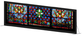
The Video Screen tool is in the Event Design tool set.
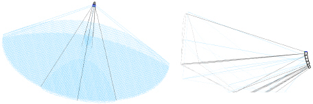
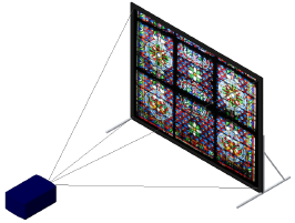
Video screen objects consist of a video screen and optional front or rear projector.
The following modes are available:

Mode |
Description |
|---|---|
Modes for the Symbol Insertion tool |
See The Symbol Insertion Tool for parameter descriptions |
Preferences |
Sets the default properties for video screen objects |
Place Screen |
Places and rotates the screen and the projector at once; the projector’s location can be adjusted after placement |
Place Screen and Projector |
Places and rotates the screen and projector independent of each other |
Screen Trim Height |
Sets the Z value of the screen at insertion |
|
Click here for a video tip about this topic (internet access required). |
To insert a video screen:
1 Click the tool and the desired symbol insertion and alignment modes.
2 Click the placement mode.
3 Enter the Screen Trim Height value on the Tool bar.
4 Insert the object in the drawing.
• In Place Screen mode, click to place the screen and projector, and click again to set the rotation.
• In Place Screen and Projector mode, click to place the screen, click again to set the screen rotation, and click again to place the projector. This is especially useful when placing video screens on hanging positions.
The first time you use the tool in a file, a properties dialog box opens. Set the default properties.
The height of the video screen and associated projector(s) depends on several factors.
• The Z value determines the distance from the active layer plane to the bottom of the screen (including the border).
• When the screen includes legs, the legs are drawn on the active layer plane unless a Floor Height value has been specified. The Floor Height distance shifts the floor, and therefore the legs, by that amount from the layer plane.
• Projector stands are inserted relative to both the Vertical Shift and Floor Height values, allowing stands to be shifted up or down from the screen’s floor as set by the Floor Height value.
• When either the screen or the projector component of the video screen object is placed on a hanging position, that component assumes the height of the hanging position and is associated with it. The height of the other component is relative to the component on the hanging position. When the screen and projector components are each placed on a different hanging position, each component assumes the height of its hanging position and is associated with it. (See Inserting Hanging Positions.)
The video screen object’s parameters can be edited from the Object Info palette.
► Clique para exibir/ocultar parâmetros.
~~~~~~~~~~~~~~~~~~~~~~~~~
 Inserting
a Blended Screen and Projector
Inserting
a Blended Screen and Projector
The Blended Screen tool is in the Event Design tool set.
The blended screen simulates projection screens that require multiple projectors to produce one large image.
The following modes are available:

Mode |
Description |
|---|---|
Modes for the Symbol Insertion tool |
See The Symbol Insertion Tool for parameter descriptions |
Preferences |
Sets the default properties for blended screen objects |
Place Screen |
Places and rotates the screen; the projectors can be added after placement |
Place Screen and Projector |
Places and rotates the screen and projectors |
Screen Trim Height |
Sets the Z value of the screen at insertion |
To insert a blended screen and projectors:
1 Click the tool and the desired symbol insertion and alignment modes.
2 Enter the Screen Trim Height value on the Tool bar.
3 Insert the object in the drawing.
• In Place Screen mode, click to place the screen, and click again to set the rotation.
• In Place Screen and Projector mode, click to place the screen, click again to set the screen rotation, and click again to place the projectors. This is especially useful when placing blended screens and projectors on hanging positions.
When projectors that are associated with a curved screen are placed on a hanging position, the projectors’ distance from the screen is determined by the hanging position geometry, not the curve of the screen.
4 The first time you use the tool in a file, a properties dialog box opens. Set the default properties.
When you use Place Screen mode to insert a blended screen, a Blended Screen object is created. Once the parameters of the blended screen and projectors have been set, click Insert Projectors from the Object Info palette to create the projectors associated with that screen. The blended screen settings control the initial projector settings, though each projector can then be set independently (by changing parameters like text position or cone display) if needed. Moving or rotating a blended screen after the projectors have been inserted also moves or rotates the associated projectors.
If projectors have already been inserted, clicking Insert Projectors deletes existing projectors and their parameter settings.
The height of the blended screen and associated projectors depends on several factors.
• The Z value determines the distance from the active layer plane to the bottom of the screen (including the border).
• When the screen includes legs, the legs are drawn on the active layer plane unless a Floor Height value has been specified. The Floor Height distance shifts the floor, and therefore the legs, by that amount from the layer plane.
• Projector stands are inserted relative to both the Vertical Shift and Floor Height values, allowing stands to be shifted up or down from the screen’s floor as set by the Floor Height value.
• When one of the blended screen components, either the screen or the projectors, is placed on a hanging position, that component assumes the height of the hanging position and is associated with it. The height of the other component is relative to the component on the hanging position. When the screen and projector components are each placed on a different hanging position, each component assumes the height of its hanging position and is associated with it. (See Inserting Hanging Positions.)
The blended screen and blended projector object parameters can be edited from the Object Info palette.
► Clique para exibir/ocultar parâmetros.
► Clique para exibir/ocultar parâmetros.
~~~~~~~~~~~~~~~~~~~~~~~~~
 Setting
the Image on the Video
Screen
Setting
the Image on the Video
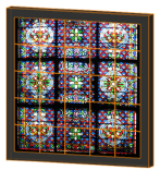
ScreenSelect an image to display on the television, video screen, or LED screen. The Vectorworks Spotlight product includes a number of sample images, or you can create your own textures. Textures must use an image color shader with constant reflectivity to display on the video screen (see Creating Textures).
If the Vectorworks file is intended for Exporting in Vision Format, associate a video source with the screen, for video display during visualizations.
To set the video screen image:
1 Select a television, video screen object, blended screen, or LED screen object. From the Object Info palette, click Edit Screen Image or Edit Array Image.
The Edit Screen Image or Edit Array Image dialog box opens.
► Clique para exibir/ocultar parâmetros.
2 If needed, adjust the image scale, and shift the image horizontally or vertically until it appears correctly in the preview.
~~~~~~~~~~~~~~~~~~~~~~~~~
 Formatting Video Screen
Object Labels
Formatting Video Screen
Object LabelsA variety of video screen object labels can be included in the drawing. Different options are available depending on the video screen object.
To select labels for display and format the text:
1 Select a video screen object. From the Object Info palette, click Text Options.
The Text Options dialog box opens.
Text Option |
Description |
|---|---|
Coverage Zone |
Displays the near and far coverage zone distances and multipliers at the specified text size and color |
Size |
Displays the screen size at the specified text size, color, and alignment |
Image Dimensions |
Displays the screen image dimensions, and if selected, the image size, screen clearance, and aspect ratio values, at the specified text size, color, and alignment. If desired, the image dimension text order can be changed from the default height x width to width x height instead, by selecting Swap Dimension Order. |
Lens Information |
Displays the projector lens size at the specified text size, color, and alignment |
Projection Distance |
Displays the distance from the projector to the screen at the specified text size, color, and alignment. Select the options to show the straight (plan) distance in 2D, direct distance (projector throw distance) in 2D, and/or actual distance in 3D. A dimension line can be included; specify the marker size. |
Projector IDs |
Labels the projector body with the entered ID information (such as projector name), at the specified text size and color. Any Note text is not displayed, but stores internal information about the projector. |
Multiple Projector Tag |
Displays the multiple projector layout for stacked projectors at the specified text size and color |
Show Array Dimensions |
For LED screen arrays, displays the overall array dimensions and total number of modules at the specified text size, color, and alignment |
Note |
Shows the Note text from the Object Info palette of the video screen object, at the specified text size, color, and alignment. A Note Label prefix can also be included; enter the contents of the prefix. |
Keep Text Horizontal |
Maintains the text in a horizontal position even when the object is rotated; deselect this option to rotate the label along with the object |
Fill Text Background |
Allows a text background fill to be used for all video screen text; by default, white is used as the fill color. To specify a different fill color, click Classes in the Object Info palette, and then select a fill color for the class of the video screen text. The class should be set to Use at Creation. |
3D Area IDs (blended screen) |
In 3D views, adds a numerical ID for each area of the blended screen (each area served by a projector), along with an optional text label. To include the text label, select Include Area ID Label and then enter the label text in Area ID Label. Specify the label text size, color, and alignment. |
2 Specify the text labels and formatting.
Once the labels have been added to the drawing, they can be moved by clicking and dragging the label control point. Click Default Text Positions from the Object Info palette of a selected video object to restore the text labels to their original locations.

~~~~~~~~~~~~~~~~~~~~~~~~~
 Identifying a Video Source for the
Vision Program
Identifying a Video Source for the
Vision ProgramWhen sending a Vectorworks file to the Vision program, a video screen object (television, video screen object, blended screen, or LED screen object) or 3D drawing geometry (solid, extrude, mesh, sweep, floor, column, roof face, 3D polygon, or 3D locus) can be identified as a video surface for use in Vision. The video source can be either a video file or a video capture device that the Vision program can identify and render.
To associate video information for use in Vision:
1 Select the video screen object or 3D geometry.
2 The next action depends on the selection.
• If a video screen object is selected, click Edit Screen Image or Edit Array Image from the Object Info palette, and then click Select Vision Video Source from the Edit Screen Image dialog box.
• If 3D geometry is selected, select Spotlight > Visualization > Select Vision Video Source.
The Select Vision Video Source dialog box opens.
► Clique para exibir/ocultar parâmetros.
When the Vectorworks file is sent to the Vision program, the video source is identified and plays on the screen or geometry.
~~~~~~~~~~~~~~~~~~~~~~~~~
 Inserting
Speakers and Speaker Arrays
Inserting
Speakers and Speaker ArraysAudio objects, including speakers and arrays of speakers, are often a required part of visualizing a room or stage layout for event planning and entertainment design, and can also be needed for theater productions. Vectorworks creates speaker system layout drawings and can perform basic audio coverage analysis. The speakers and speaker arrays can be labeled with information and calculated data and can display the optimum listening area for up to three ranges.

The Vectorworks Spotlight software includes default speaker data in the audio tools folders located in the Vectorworks application folder [Vectorworks]\Libraries. You can also save speaker data to a library file, which can be shared with others, and you can import speaker data from other files. The file must be located within the Audio Tools\Speakers or Audio Tools\Bumpers folders.
Another way to share speakers or speaker arrays is to create symbols from them and import the symbols into another file.
~~~~~~~~~~~~~~~~~~~~~~~~~
 Inserting
Speakers
Inserting
Speakers Mode |
Tool |
Tool set |
|---|---|---|
Modes for The Symbol Insertion Tool |
Speaker
|
Event Design |
Use the Speaker tool to insert individual speakers that are not part of an array. Manually-inserted speakers can be placed as single speakers, or as several speakers arranged in a column. A variety of supports and labeling options are available. Use a speaker type with pre-set data from the speaker library file that is included with the Vectorworks Spotlight product (in the Vectorworks application folder [Vectorworks]\Libraries). You can also create a speaker with custom data and save it to the library for future use and sharing.
To insert a speaker:
1 Click the tool and the desired insertion modes.
2 Click to place the object in the drawing, and click again to set the rotation.
The first time you use the tool in a file, a properties dialog box opens. Set the default properties. The properties can be edited from the Object Info palette.
► Clique para exibir/ocultar parâmetros.
~~~~~~~~~~~~~~~~~~~~~~~~~
 Inserting Speaker
Arrays
Inserting Speaker
Arrays Mode |
Tool |
Tool set |
|---|---|---|
Modes for The Symbol Insertion Tool |
Speaker Array
|
Event Design |
Large venues require the use of speaker arrays, which consist of speakers stacked in a column and topped by a bumper (top mounting bracket). Up to three different types of speakers can be included in an array. The speakers can each be tilted differently to provide maximum audio coverage for the audience.
To insert a speaker array:
1 Click the tool and the desired insertion modes.
2 Click to place the object in the drawing, and click again to set the rotation.
The first time you use the tool in a file, a properties dialog box opens. Set the default properties.
3 A bumper is inserted. From the Object Info palette, click Configure Array.
The Array Detail and Configuration dialog box opens. Specify the bumper parameters on the Bumper tab.
► Clique para exibir/ocultar parâmetros.
4 On the Speaker A, B, and C tabs, configure up to three types of speakers for inclusion in the array.
► Clique para exibir/ocultar parâmetros.
5 Set up the array configuration on the Array tab.
► Clique para exibir/ocultar parâmetros.
6 From the Object Info palette, click Populate Array to add the speakers to the drawing.
The speaker array properties can be edited from the Object Info palette. To edit the array, select the bumper. Individual speakers can be selected and certain parameters can be set independently, but since the speakers are controlled by the array, many of their parameters are not available (see Inserting Speakers for parameter descriptions).
► Clique para exibir/ocultar parâmetros.
~~~~~~~~~~~~~~~~~~~~~~~~~
 Formatting
Speaker Object Labels
Formatting
Speaker Object Labels A variety of speaker and speaker array labels can be included in the drawing. Different options are available for speakers and speaker arrays. A speaker array, as well as the individual speakers that make up the array, can be labeled.
To select labels for display and format the text:
1 Select a speaker or speaker array object (bumper). From the Object Info palette, click Text Options.
The Text Options dialog box opens.
► Clique para exibir/ocultar parâmetros.
2 Specify the text label elements and formatting.
Once the label has been added to the drawing, it can be moved by clicking and dragging the label control point. Click Default Text Position from the Object Info palette of a selected speaker or array object to restore the text label(s) to the original location.

~~~~~~~~~~~~~~~~~~~~~~~~~
 Inserting
a Stage Lift
Inserting
a Stage LiftMode |
Tool |
Tool set |
|---|---|---|
Modes for The Symbol Insertion Tool |
Stage Lift
|
Rigging |
A stage lift object can be added to a drawing to represent the typical adjustable support device commonly found on stage for supporting speakers, trusses, and other stage equipment. The stage lift can be shown extended or collapsed, with a specific appearance and fork position, and can be labeled.

To insert a stage lift:
1 Click the tool and the desired insertion modes.
2 Click to place the object in the drawing, and click again to set the rotation.
The first time you use the tool in a file, a properties dialog box opens. Set the default properties. The properties can be edited from the Object Info palette.
► Clique para exibir/ocultar parâmetros.
~~~~~~~~~~~~~~~~~~~~~~~~~
 Formatting
Stage Lift Labels
Formatting
Stage Lift Labels A variety of stage lift labels can be included in the drawing. Text must be entered into the associated field of the Object Info palette for the label to be included.
To select labels for display and format the text:
1 Select a stage lift object. From the Object Info palette, click Text Options.
The Text Options dialog box opens.
► Clique para exibir/ocultar parâmetros.
2 Specify the text label elements and formatting.
Once the label has been added to the drawing, it can be moved by clicking and dragging the label control point. Click Default Text Position from the Object Info palette of a selected stage lift object to restore the text label(s) to the original location.

~~~~~~~~~~~~~~~~~~~~~~~~~
 Inserting Stage Structures
Vectorworks includes several different types of rectangular, round, and free-form stage structures, along with the specialized, industry-standard steps and ramps to access them. These theatrical and event staging structures can range from simple, basic forms to complex structures with customized textures for a realistic appearance. The event design commands also make use of these structures.
~~~~~~~~~~~~~~~~~~~~~~~~~
 Inserting
a Stage Deck
Inserting
a Stage DeckMode |
Tool |
Tool set |
|---|---|---|
• Bottom Insertion Point • Top Insertion Point |
Stage Deck
|
Event Design |
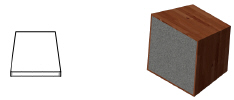
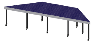
The Stage Deck tool inserts rectangular and rounded portable stage structures into a drawing. The type, shape, size, appearance, and presence of railings can be customized. Place several stage decks to create a large stage area.
Place the first stage deck into the drawing using the Bottom Insertion Point mode. Once the first stage has been placed, switch to Top Insertion Point mode to easily align the new stage deck with the existing ones.
To insert a stage deck:
1 Click the tool and mode, and then click the alignment mode (see The Symbol Insertion Tool).
2 Click to place the object in the drawing, and click again to set the rotation.
The first time you use the tool in a file, a properties dialog box opens. Set the default properties. The properties can be edited from the Object Info palette.
► Clique para exibir/ocultar parâmetros.
~~~~~~~~~~~~~~~~~~~~~~~~~
 Inserting
a Stage Plug
Inserting
a Stage PlugMode |
Tool |
Tool set |
|---|---|---|
Modes for the Polyline Tool |
Stage Plug
|
Event Design |
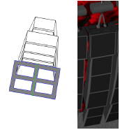
The Stage Plug tool inserts custom shaped stage structures into a drawing. The type, shape, size, and appearance can be customized.
To insert a stage plug:
1 Click the tool and the desired creation mode.
2 Click to set the stage’s start point.
3 Click to set the end of the segment and the beginning of the next. Continue drawing segments in this manner until the stage object is complete.
The first time you use the tool in a file, a properties dialog box opens. Set the default properties.
The stage plug can be reshaped with the Reshape tool; see Remodelando Objetos. The stage plug parameters can be edited in the Object Info palette.
► Clique para exibir/ocultar parâmetros.
~~~~~~~~~~~~~~~~~~~~~~~~~
 Formatting
Stage Labels
Formatting
Stage LabelsA variety of stage labels can be included in the drawing. For some options, text must be entered into the associated field of the Object Info palette for the label to be included.
To select labels for display and format the text:
1 Select a stage deck or stage plug object. From the Object Info palette, click Text Options.
The Text Options dialog box opens.
► Clique para exibir/ocultar parâmetros.
2 Specify the text label elements and formatting.
Once the label has been added to the drawing, it can be moved by clicking and dragging the label control point. Click Default Text Positions from the Object Info palette of a selected stage object to restore the text label(s) to the original location.

~~~~~~~~~~~~~~~~~~~~~~~~~
 Inserting
Stage Steps
Inserting
Stage StepsMode |
Tool |
Tool set |
|---|---|---|
Modes for The Symbol Insertion Tool |
Stage Steps
|
Event Design |
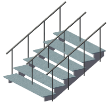
The Stage Steps tool inserts portable steps typically used with temporary stage structures into a drawing. The type, shape, size, appearance, and presence of railings can be customized.
To insert stage steps:
1 Click the tool and the desired insertion modes.
2 Click to place the object in the drawing, and click again to set the rotation.
The first time you use the tool in a file, a properties dialog box opens. Set the default properties. The properties can be edited from the Object Info palette.
► Clique para exibir/ocultar parâmetros.
~~~~~~~~~~~~~~~~~~~~~~~~~
 Formatting
Stage Step Labels
Formatting
Stage Step LabelsA variety of stage step labels can be included in the drawing. For some options, text must be entered into the associated field of the Object Info palette for the label to be included.
To select labels for display and format the text:
1 Select a stage steps object. From the Object Info palette, click Text Options.
The Text Options dialog box opens.
► Clique para exibir/ocultar parâmetros.
2 Specify the text label elements and formatting.
Once the label has been added to the drawing, it can be moved by clicking and dragging the label control point. Click Default Text Position from the Object Info palette of a selected stage steps object to restore the text label(s) to the original location.

~~~~~~~~~~~~~~~~~~~~~~~~~
 Inserting
a Stage Ramp
Inserting
a Stage RampMode |
Tool |
Tool set |
|---|---|---|
Modes for The Symbol Insertion Tool |
Stage Ramp
|
Event Design |
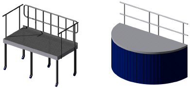
The Stage Ramp tool inserts the type of portable ramp typically used with temporary stage structures into a drawing. The type, shape, size, appearance, and presence of railings can be customized.

To insert a stage ramp:
1 Click the tool and the desired insertion modes.
2 Click to place the object in the drawing, and click again to set the rotation.
The first time you use the tool in a file, a properties dialog box opens. Set the default properties. The properties can be edited from the Object Info palette.
► Clique para exibir/ocultar parâmetros.
~~~~~~~~~~~~~~~~~~~~~~~~~
 Formatting
Stage Ramp Labels
Formatting
Stage Ramp LabelsA variety of stage ramp labels can be included in the drawing. For some options, text must be entered into the associated field of the Object Info palette for the label to be included.
To select labels for display and format the text:
1 Select a stage ramp object. From the Object Info palette, click Text Options.
The Text Options dialog box opens.
► Clique para exibir/ocultar parâmetros.
2 Specify the text label elements and formatting.
Once the label has been added to the drawing, it can be moved by clicking and dragging the label control point. Click Default Text Positions from the Object Info palette of a selected stage ramp object to restore the text label(s) to the original location.

~~~~~~~~~~~~~~~~~~~~~~~~~
 Replacing Stage Decks and Trusses with Symbols
Stage deck objects and straight or curved trusses can be replaced with symbols. This improves the counts of the objects in reports and makes the representation of identical objects in the drawing consistent. In addition, after the initial stages of design, generic stage decks or trusses can be replaced with symbols that contain manufacturer-specific parameters.
Select either stage deck or truss objects. If both are selected, the Choose One Type of Object dialog box opens, and you are prompted to choose one or the other type of object.
|
Click here for a video tip about this topic (internet access required). |
Command |
Path |
|---|---|
Replace with Stock Symbols |
Spotlight > Object Conversion |
To replace selected stage deck objects in the drawing with stock symbols:
1 Select the stage deck objects to be replaced.
2 Select the command.
The Replace Object with Stock Symbol dialog box opens.
► Clique para exibir/ocultar parâmetros.
3 Select each category of identical stage decks, and then choose the symbol to replace them. Click in the Action column until Replace displays. Other options in the Action column include Keep or Delete; if you clicked Replace but instead, you wish to remove or retain the original stage deck, click to change the action.
Command |
Path |
|---|---|
Replace with Stock Symbols |
Spotlight > Object Conversion |
To replace selected straight or curved truss objects in the drawing with stock symbols:
1 Select the truss objects to be replaced.
Trusses that have been converted to hanging position objects can be selected. Trusses that have been rotated in 3D cannot be selected.
2 Select the command.
The Replace Object with Stock Symbol dialog box opens.
► Clique para exibir/ocultar parâmetros.
3 Select each category of identical trusses, and then choose the symbol to replace them. Click in the Action column until Replace displays. Other options in the Action column include Keep or Delete; if you clicked Replace but instead, you wish to remove or retain the original truss, click to change the action.
~~~~~~~~~~~~~~~~~~~~~~~~~