 EscadasEscadas
Os produtos Vectorworks Landmark e Spotlight oferecem uma ferramenta de Escada Simples que pode ser usada em desenhos que não exijam uma escada complexa. Já os produtos Vectorworks Architect, Landmark e Designer incluem uma ferramenta de Escada, e as configurações podem ser alteradas para que você possa adicionar a ferramenta Escada Simples.
Estas ferramentas permitem construir escadas com geometrias variadas. A escada é um objeto híbrido que oferece controle sobre a aparência 2D, bem como o componente 3D, para apresentações de planta e de desenho. A ferramenta Escada traz diversas opões, detalhes e configurações, e realiza várias tarefas de escadaria automaticamente.
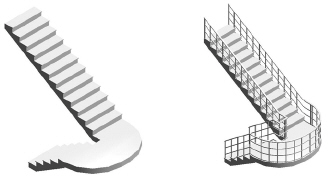
A ferramenta Escada oferece um conjunto de configurações comuns (reta, em L, em U, em O e circular). Isto permite a criação de estilos a partir dos conjuntos de grupos controladores de parâmetros da geometria e dos atributos de exibição, que podem ser salvos e reutilizados em outras escadas. A escada pode ser configurada para determinar a sua própria altura de piso a piso com base nas camadas conectadas pela escada, e pode tirar proveito de um projeto definido com andares (requer Vectorworks Architect). A escada pode ter representações gráficas separadas para o andar superior e o andar inferior. Com isto você não precisa desenhar escadas em duas camadas diferentes para representar a mesma escada, e nem editá-las separadamente. As opções de quebra de escada podem ser configuradas de forma diferente em cada camada, permitindo que você obtenha a aparência desejada na vista Topo/Plano. Toda a configuração da escada pode ser salva em um símbolo para ser reutilizada ou compartilhada com outros usuários, criando uma biblioteca de padrões de escadas. Os parâmetros também podem ser copiados de uma escada para outra.Apesar da variação geométrica da escada ser restrita, o nível de controle sobre os atributos 2D e 3D é grande. As escadas podem ser criadas como objetos somente 2D ou objetos híbridos.
~~~~~~~~~~~~~~~~~~~~~~~~~
 Criando Escadas Simples
Ferramenta |
Conjunto de Ferramentas |
|---|---|
Escada Simples
|
Building Shell |
Um objeto de escada simples é disponibilizado para adicionar uma representação básica de uma escada em um desenho. Produtos Design Series contém duas ferramentas adicionais de escadas quando o projeto que requer escadas complexas, detalhadas. Veja Inserindo Escadas).
Para inserir uma escada simples:
1 Clique na ferramenta.
2 Clique para posicionar a Escada Simples no desenho, e clique novamente para definir a rotação da escada.
Se esta for a primeira vez que estiver inserindo uma escada no desenho, a janela de diálogo de propriedades da escada abrirá. Defina as propriedades padrão e clique em OK.
► Clique para exibir/ocultar parâmetros.
 Criando
uma Escada
Criando
uma EscadaModo |
Ferramenta |
Conjunto de Ferramentas |
|---|---|---|
Inserir |
Escada
|
Paredes / AEC |
Se a escada tiver uma representação de camada inferior e camada superior, ou se a elevação total for definida por camada ou elementos de escada, ela deverá ser inserida na camada que representa o menor dos dois andares que ela conecta.

Modo |
Descrição |
|---|---|
Inserir |
Insere uma escada com os parâmetros especificados em Preferências |
Pegar |
Pega os atributos selecionados de uma escada para ser transferida para outra escada; os atributos são selecionados nas preferências da escada |
Aplicar |
Transfere atributos selecionados de uma escada para outra; os atributos são selecionados nas preferências da escada e pegados no modo Pegar. |
Atualizar |
Atualiza todas as escadas no desenho, o que é necessário quando a escala da camada mudou e uma mudança na representação esquemática da escada também é necessária |
Def. Ativo |
Abre o Seletor de Recursos para selecionar um símbolo de escada para posicionamento; clique-duplo em um recurso para ativá-lo. |
Preferências |
Abre a janela de diálogo Configurações da Escada, para definir os parâmetros da escada padrão |
Para inserir uma escada:
1 Na camada apropriada, clicar na ferramenta e no modo.
2 Faça um dos seguintes:
• Para usar um recurso da escada existente, clicar em Def. Ativo no Seletor de Recursos, localize o recurso desejado e clique-duplo para ativá-lo.
• Para criar uma escada personalizada, clicar em Preferências. A janela de diálogo Configurações da Escada abrirá. As configurações são agrupadas em várias abas de parâmetros relacionados, listadas na parte superior da caixa de diálogo. Selecione cada aba e especifique os parâmetros da escada. Esses parâmetros podem ser editados para as escadas colocadas da Paleta Info de Objeto.
Alternativamente, inserir a escada padrão e, em seguida, clicar em Configurações na Paleta Info de Objeto ou simplesmente clique-duplo em uma escada existente para definir os parâmetros da escada.
3 Quando os parâmetros de configuração da escada em cada aba estiverem definidos, considere se deseja salvar a escada como um símbolo.
Se a mesma escada personalizada for usada inúmeras vezes em um desenho, ou será usada em outro desenho ou por outro projetista, isso elimina a necessidade de aplicar parâmetros repetidamente, maximiza a eficiência da memória e permite a edição global de símbolos. Veja Conceito: Vectorworks Símbolos.
Se você não deseja criar um símbolo, os atributos da escada podem ser facilmente transferidos.
4 Clicar no desenho para inserir a escada. Clicar novamente para definir a rotação da escada.
Para editar os parâmetros da escada para uma escada colocada, clicar em Configurações na Paleta Info de Objeto, clique-duplo na escada para abrir a janela de diálogo Configurações da Escada ou clique-direito em uma escada e selecionar Editar no menu de contextual. Alguns parâmetros estão disponíveis diretamente na Paleta Info de Objeto.
Cada aba dos parâmetros da escada é descrita nas seções a seguir. Conforme os parâmetros são definidos, a visualização exibe dinamicamente a aparência da escada.
• Stair Settings: Geometry Tab
• Stair Settings: 2D Graphics Tab
• Stair Settings: Construction Tab
• Stair Settings: Railings Tab
• Stair Settings: Graphic Attributes Tab
• Transferring Stair Properties
~~~~~~~~~~~~~~~~~~~~~~~~~
 Stair
Settings: General Tab
Stair
Settings: General Tab1 Click the General tab to set the stair configuration.
Parâmetro |
Descrição |
|---|---|
General Configuration |
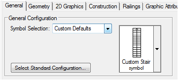
Select either an existing symbol or a standard configuration as the basis for the stair. This selection sets initial parameter values that can be edited to create a custom stair. |
Symbol Selection |
If a stair symbol was selected in Active Def on the Tool bar, the symbol name displays here. Otherwise, to use an existing stair from the resource libraries, click Symbol Selection; from the Resource Selector, double-click a resource to activate it. |
Select Standard Configuration |
If no symbol is selected, select an initial stair configuration that most closely matches the type of custom stair to create. The Select a Stair Configuration dialog box opens; select one of the configurations. If there are any current stair parameters that should be saved and transferred to the new stair, select the category or categories from Transfer settings from current stair. |
General Settings |
|
Component |
Select whether to create a 2D only or hybrid 2D/3D object |
Class |
To control appearance and visibility, select a class from the list of classes present in the drawing, or create a new class |
Orientation |
For stairs with oblique/winder treads, specifies the side of the stair with the shortest tread depth; for L- and U-Stairs, determines the direction of travel |
General Geometry |
Specify overall parameters for the stair configuration. These general parameters can be set here or on the Geometry tab. Values entered here are also set on the Geometry tab. For stairs with multiple flights, the Stair Width value entered on the General tab is applied to all flights on the Geometry tab. |
Lock button |
For any parameter, locks the parameter value, forcing the other parameters to recalculate to automatically adjust |
Preview |
Displays a preview of the current stair configuration |
Preview for |
Select either a detailed or schematic view for the preview |
Stair detail status (in parentheses) |
Stair details may be hidden at certain layer scales, depending on the detail display setting on the Display tab of the document preferences (see Document Preferences: Display Tab). Depending on the setting, the status indicates whether stair details will display for stairs in the drawing, or shows the scale required for the details to display. |
View |
Select a view for the preview from the list of standard views; 3D views are not available for a 2D only stair |
Render Mode |
Select a render mode for the preview from the list of available modes |
Calculate |
Forces the stair object to recalculate based on the current set of parameter values |
Previous Stair |
Loads the parameter values of the most recently created stair |
Save as Symbol |
Creates a symbol based on the current settings |
Use Minimum/Maximum Values |
Enables the use of minimum/maximum settings for the stair angle, tread depth, riser height, and step length. Normally, this option should be enabled to create stairs with valid proportions and settings that meet standard requirements. However, during the initial design phase, it may be convenient to temporarily disable the settings while exploring various geometry and design possibilities. |
Edit |
Opens the Min./Max. Settings dialog box |
2 If you switch to another stair configuration after making parameter changes on any tab, the New Stair dialog box opens.
Switching to a new configuration loses any parameter settings that have already been made. The settings from the current stair configuration can be transferred to the new stair if needed. Select specific settings to transfer, or click All or None to select or deselect all the settings.
~~~~~~~~~~~~~~~~~~~~~~~~~
 Stair
Settings: Geometry Tab
Stair
Settings: Geometry Tab1 Click the Geometry tab to set both basic and detailed stair geometry based on the configuration selected on the General tab. The geometry parameters automatically influence each other; entering a few desired parameters causes the remaining parameters to adjust accordingly.
The diagrams next to each parameter indicate the relevant area of the stair.
► Clique para exibir/ocultar parâmetros.
2 If setting the stair Total Rise by layer elevation instead of by a specific value, the height of the stair can be constrained by layer or story elements at its top and bottom boundaries; the lower floor and upper floor indicate the two stories the stair connects. Adjusting a bounding element causes the height of the stair to automatically change accordingly.
Select By Layer Elevation; the Total Rise by Layer Elevations dialog box opens.
► Clique para exibir/ocultar parâmetros.
3 The Preview contains two preview graphics.
The lower preview graphic displays a detailed section/elevation view of the treads and risers, and indicates the current rise angle.

The upper preview graphic displays the Top/Plan view and is interactive.
• Click an upper or lower tread to set the oblique tread parameters for the highlighted treads.
• L- and U-Stairs have clickable red areas at the corner of the landing. Click each area to set corner parameters for the inside and outside corners of the landing. The Stair Landing Corners dialog box opens. For configurations that allow angles other than 90 degrees, enter the desired Length or Radius; the corner style parameters update automatically. For each corner, set the Corner Style to the desired angle, or round the corner by specifying a chamfer or fillet value.
• For Double-U and Triple-L configurations, some parts of the stair may overlap in the Top/Plan preview, making it difficult to select and edit the intended corner parameters. Before clicking the red areas to set corner parameters for these configurations, select whether the preview displays the Upper part of stair or Lower part of stair.
• For fixed angle winder stair configurations, click the stair winder to set the winder parameters. The Winder Parameters dialog box opens. Specify the number of treads for the winder section of the stair, and select whether the winder tread depths should match the tread depths for the straight parts of the stair. If maintaining a constant tread depth is desired, the minimum winder tread depth may need to be adjusted to prevent errors.
The Geometry tab allows values to be locked, which forces other parameters to recalculate while maintaining appropriate calculated values for the stair. Occasionally, an invalid entry is attempted, which generates an error due to other locked values or to minimum/maximum restrictions.
When this occurs, an Error Correction dialog box opens, describing the reason for the error and offering several options to correct the problem. Select one of the options from the list and click OK to return to the stair parameters.
In the event that no successful correction options are available, an alert dialog box opens instead, to notify you of the error and offer several possible options to avoid it.
Situations which can generate an error or alert include:
• The total rise calculation is based on multiplying the number of risers by the riser height, and therefore cannot be edited without changing one of the values. Similarly, the number of risers or riser height cannot be edited when the total rise is locked.
Parameter to be edited |
Locked |
Unlocked |
Resolution |
|---|---|---|---|
Total rise |
Riser Height |
Num. of Risers |
Change the riser height or the total rise and number of risers as suggested, or return to previous values |
Total rise |
Num. of Risers |
Riser Height |
Modify the riser height, or the riser height and the number of risers as suggested, or return to previous values |
Total rise |
Riser Height and Num. of Risers |
N/A |
Change the riser height and/or the number of risers as suggested, or return to previous values |
Riser height |
Total rise |
N/A |
Modify the total rise, or the riser height and number of risers as suggested, or return to previous values |
Number of risers |
Total rise |
N/A |
Change the total rise, or the riser height/step length, or the riser height and number of risers as suggested, or return to previous values |
• The total rise of the stair and the stair length (or sweep angle, for circular stairs) impact other values such as tread depth, riser height, and the number of risers. When the length/sweep angle is locked, it may become impossible to obtain valid entries for the other parameters. Since the stair length or sweep angle is a multiple of the tread depth, one cannot be edited when the other is locked.
Parameter to be edited |
Locked |
Resolution |
|---|---|---|
Total rise |
Length or Sweep Angle |
Change the number of risers and step length, or unlock the length/sweep angle as suggested, or return to previous values |
Tread depth |
Length or Sweep Angle |
Modify the length/sweep angle, and/or change the number of risers and the tread depth as suggested, or return to previous values |
Length or Sweep Angle |
Tread Depth |
Change the tread depth, and/or the number of risers, or change the risers and length/sweep angle as suggested, or return to previous values |
• Restrictions defined in the Min/Max Settings may prevent the parameter change. Options in the Error Correction dialog box may allow the restrictions to be slightly loosened, or even completely disabled, so that the stair can be created (this applies especially during the design phase when experimenting with parameter values).
• Winders may be pushed into the straight sections of the stair if one of the Side values changes drastically, resulting in potential calculation errors at the stair corners. The number and range of winders at the corners, or the corner style at the stair’s inner corners, may require modification.
~~~~~~~~~~~~~~~~~~~~~~~~~
 Stair Settings: 2D Graphics
Tab
Stair Settings: 2D Graphics
TabThe remaining four stair configuration tabs have a method of saving and recalling each tab’s settings or style. The settings on the tab can be saved as a set and then loaded, replacing the current tab parameters.
1 Click the 2D Graphics tab to set the stair’s 2D appearance on lower and, if desired, upper floors. The lower floor is always the floor where the stair has been placed. Selecting display options for the upper floor is optional; the upper floor representation is usually on another layer, and can be specifically selected here. These parameters apply only to the Top/Plan view, and do not affect the 3D appearance of the stair.
► Clique para exibir/ocultar parâmetros.
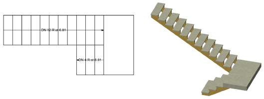
2 Click Stair Data for the lower, and optionally, the upper floor, to set the display of the 2D stair information text.
The Stair Data Settings dialog box opens. The stair configuration determines the number of available run or flight parameters. Stair data text appearance is set on the Graphic Attributes tab.
► Clique para exibir/ocultar parâmetros.
The position of the stair run and note text can be adjusted by moving its control point.

~~~~~~~~~~~~~~~~~~~~~~~~~
 Stair Settings: Construction Tab
The settings on the tab can be saved as a set and then loaded, replacing the current tab parameters.
1 Click the Construction tab to specify stair construction parameters. The parameters displayed depend on the selected construction configuration.
► Clique para exibir/ocultar parâmetros.
2 For a solid or concrete Construction Configuration, click Upper/Lower Floor Connection Detail to open the Upper Floor Connection Detail dialog box or Lower Floor Connection detail dialog box.
► Clique para exibir/ocultar parâmetros.
► Clique para exibir/ocultar parâmetros.
~~~~~~~~~~~~~~~~~~~~~~~~~
 Stair
Settings: Railings Tab
Stair
Settings: Railings TabThe settings on the tab can be saved as a set and then loaded, replacing the current tab parameters.
Click the Railings tab to set the stair’s handrail and guardrail parameters. The Railings tab is divided into three panes. On the left, the handrail and guardrail categories display, along with each current setting for the left, right, or both sides of the stair. Handrail and guardrail parameters are set separately. Click a disclosure arrow to reveal handrail or guardrail parameter categories. Select a category to edit its parameter settings in the middle pane. On the right, three previews display the railing cross-section, top/plan stair view, and isometric stair view.
► Clique para exibir/ocultar parâmetros.
~~~~~~~~~~~~~~~~~~~~~~~~~
 Stair
Settings: Graphic Attributes Tab
Stair
Settings: Graphic Attributes TabThe settings on the tab can be saved as a set and then loaded, replacing the current tab parameters.
1 Click the Graphic Attributes tab to specify the appearance of stair components.
► Clique para exibir/ocultar parâmetros.
2 The graphic attributes of each stair part are listed. Double-click an item to edit it.
An Attributes dialog box with the name of the item is displayed. See The Attributes Palette for information on setting attributes.
~~~~~~~~~~~~~~~~~~~~~~~~~
 Managing
Stair Styles
Managing
Stair StylesIn the Stair Settings dialog box, the 2D Graphics, Construction, Railings, and Graphic Attributes tabs have the option of saving the current tab’s settings as a style that can be recalled later. The stair minimum/maximum settings can also be saved as a style set.
To save tab settings as a style:
When the tab parameters have been set, click Save (located in the Styles area at the top left of the tab). The Save Style dialog box opens.
► Clique para exibir/ocultar parâmetros.
The new style name appears in the Styles list.
To recall a saved style:
Select the style from the Styles list. Any currently set parameters are replaced by those of the saved style set. The Styles list contains saved styles as well as a limited number of default styles.
Styles can be renamed and deleted.
Default styles (located in the application folder) cannot be renamed or deleted.
To manage styles:
Click Manage Styles (located in the Styles area at the top left of the tab). The Styles dialog box opens, listing all currently saved style sets and their saved location.
► Clique para exibir/ocultar parâmetros.
~~~~~~~~~~~~~~~~~~~~~~~~~
 Saving
a Stair as a Symbol
Saving
a Stair as a SymbolThe stair configuration, along with all its parameters, can be saved as a symbol for use again in the current file or in a library file. The stair is saved as a red symbol and becomes a plug-in object with pre-set parameters when inserted. See Símbolos.
To save the stair as a symbol:
1 From the Stair Settings dialog box, click Save as symbol.
The Save Stair dialog box opens.
► Clique para exibir/ocultar parâmetros.
2 Select whether to save the stair symbol in the current file or in a library file.
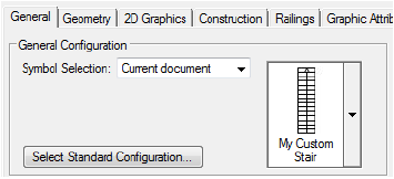
• To save the symbol in a library file, select Save as template in library file and enter a name for the symbol. It will be available from the General tab’s Symbol Selection list under the Custom Defaults category. Library files can be shared among users.
• To save the symbol in the current file, select Save as symbol in current document, enter a name for the symbol, and select a symbol folder destination for the symbol by double-clicking on the selected symbol folder name. It will be available from the General tab’s Symbol Selection list under the Current Document category, and also from the Resource Manager. Symbols can be shared by exporting them from the Resource Manager (see Exporting Resources).
~~~~~~~~~~~~~~~~~~~~~~~~~
 Setting
Minimum and Maximum Values for Stair Geometry Parameters
Setting
Minimum and Maximum Values for Stair Geometry ParametersWhen setting stair parameters, a geometry “envelope” can be set to specify the allowable value ranges for tread depth, riser height, step length, and stair angle. Setting these values can assist with creating proportional stair geometry that complies with standards.
During the initial phases of design, it may be convenient to temporarily disable the minimum/maximum restrictions by deselecting Use Minimum/Maximum Values from the Stair Settings dialog box.
The stair minimum/maximum settings can be saved as a style set and then loaded, replacing the current dialog box parameters.
To set minimum and maximum stair parameter ranges:
From the Geometry pane of the Stair Settings dialog box, click Edit. The Min/Max Settings dialog box opens.
► Clique para exibir/ocultar parâmetros.
~~~~~~~~~~~~~~~~~~~~~~~~~
 Stair Properties
All of the stair parameters can be edited by clicking Settings from the Object Info palette. Some stair parameters can be edited directly from the Object Info palette; specific tabs on the Stair Settings dialog box can be accessed directly from the Object Info palette by clicking 2D Graphics, Construction, Railings, or Graphic Attributes.
The stair object’s General Geometry parameters from the Stair Settings General tab and the total number of risers display on the Object Info palette as static text for quick reference. These parameters must be edited on the Stair Settings dialog box.
Stair parameters are described in the sections that describe individual tabs in the Criando uma Escada section of the help.
~~~~~~~~~~~~~~~~~~~~~~~~~
 Transferring
Stair Properties
Transferring
Stair PropertiesMode |
Tool |
Tool set |
|---|---|---|
Pick up |
Stair
|
Building Shell |
Specific stair parameters can be transferred from one stair to another.
To transfer stair attributes:
1 Click the tool and mode.
2 Click Preferences to set the transfer parameters in the Stair Settings dialog box.
The transfer attributes are not available by clicking Settings from the Object Info palette.
3 Click the Transfer tab.
► Clique para exibir/ocultar parâmetros.
4 Select the attributes to transfer, and select whether the attributes should become Stair tool defaults and/or should also apply to all stairs in the file.
5 In Pick up mode, click the stair with the desired attributes.
The cursor changes to an eyedropper, and the source stair is highlighted in red.
6 Move the cursor to the target stair, and click Apply mode from the Tool bar.
Press the Option (Mac) or Ctrl (Windows) key to switch between the Pick up and Apply modes.
7 Click the target stair to transfer the selected attributes.
~~~~~~~~~~~~~~~~~~~~~~~~~
 Inserting Elevators
Tool |
Tool set |
|---|---|
Elevator
|
Building Shell |
The Elevator tool provides access to a variety of standard elevator types, including resources from manufacturers’ catalogs and your own elevator styles (see Concept: Plug-in Object Styles), in addition to individual objects created using the tool.

To insert an elevator:
1 Click the tool.
2 From the Tool bar, click either Active Def to select an existing resource from the Resource Selector, or click Preferences and set the default parameters to create a custom object.
3 Click on the drawing to place the object, and click again to set the rotation. The properties can be edited from the Object Info palette.
► Clique para exibir/ocultar parâmetros.
4 Optionally, after placement you can create a plug-in object style, which combines catalog parameters (with a fixed value established by the manufacturer), style parameters (with a fixed value established by the style) and instance parameters (which can be set independently for each instance of the styled object in the drawing). See Creating Plug-in Object Styles.
 Inserting
Escalators
Inserting
EscalatorsTool |
Tool set |
|---|---|
Escalator
|
Building Shell |
The Escalator tool provides access to a variety of standard escalator types available from the Resource Manager, in addition to individual objects created using the tool. The tool can be used to create your own escalator styles (see Concept: Plug-in Object Styles).
To insert an escalator:
1 Click the tool.
2 From the Tool bar, click either Active Def to select an existing resource from the Resource Selector, or click Preferences and set the default parameters to create a custom object.
3 Click on the drawing to place the object, and click again to set the rotation. The properties can be edited from the Object Info palette.
► Clique para exibir/ocultar parâmetros.
4 Optionally, after placement you can create a plug-in object style, which combines style parameters (with a fixed value established by the style) and instance parameters (which can be set independently for each instance of the styled object in the drawing). See Creating Plug-in Object Styles.
 Inserting
Ramps
Inserting
RampsTool |
Tool set |
|---|---|
Ramp
|
Building Shell |
To insert a ramp:
1 Click the tool.
2 From the Tool bar, click either Active Def to select an existing resource from the Resource Selector, or click Preferences and set the default parameters to create a custom object.
3 Click on the drawing to place the object, and click again to set the rotation. The properties can be edited from the Object Info palette.
► Clique para exibir/ocultar parâmetros.
4 Optionally, after placement you can create a plug-in object style, which combines style parameters (with a fixed value established by the style) and instance parameters (which can be set independently for each instance of the styled object in the drawing). See Creating Plug-in Object Styles.


