Focusing InstrumentsFocusing Instruments
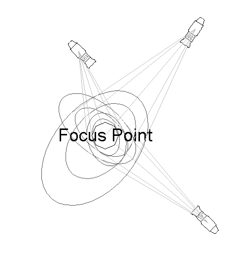
To focus a lighting instrument assembly and beam on a particular area or object, a focus point needs to be defined.
The focus point can also be used to create Magic Sheets that show the instruments focused on a particular area (see “Magic Sheets” on page 970). In addition, the focus point can be used as one of the criteria for finding instruments with the Find and Modify command (see “Find and Modify” on page 886). It is also possible to select all lighting devices assigned to a particular focus point for quick editing (see “Editing Lighting Instruments” on page 876).
An object defined as a focus point specifies where instrument assemblies and light beams should be directed. If the focus point is moved, any instruments that are aimed at it update their focus position based on the focus point information.
Like lighting positions and instruments, focus points should be inserted on their own design layer, to facilitate selection, viewing, and printing. Alternatively, it is acceptable to insert the focus points on the same design layer as the scenic elements. Focus points can also be inserted into their own classes.
A 3D stage object can be used as a focus point for lighting instruments by naming it as the focus point in the instrument Object Info palette (see “Lighting Instrument Properties” on page 876).

To create a focus point object:
1. Click the Focus Point tool from the Spotlight tool set.
2. Click Preferences from the Tool bar to specify the default focus point settings. These settings can be changed later for existing focus points from the Object Info palette.
The Focus Point Properties dialog box opens.
Click to show/hide the parameters.
3. Click on the plot to insert the focus point object.
4. The Place Focus Point dialog box opens. Enter the name of the focus point, the focus height above the stage floor, and then click OK.
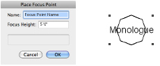
The focus point name is required later to specify the focus point for the lighting instruments.
The name of a focus point can be changed on the Data tab of the Object Info palette, and can be updated in the drawing file by selecting Reset on the Shape tab of the Object Info palette. Place focus points in their own class so they can be easily hidden for a 3D rendering. Alternatively, select Standard 2D or Locus Points Only for the Focus Point Shape.
~~~~~~~~~~~~~~~~~~~~~~~~~
 Assigning
a Focus Point to a Lighting Instrument
Assigning
a Focus Point to a Lighting Instrument One or more instruments and/or multi-circuit instruments can be focused on a focus point. The focus point is used to draw light beam representations (see “Drawing Light Beam Representations” on page 899), calculate photometric values (see “Obtaining Photometric Data” on page 899) and for rendering gobo projections (see “Gobo Projection Requirements” on page 976). In 3D views, the instrument rotates to point automatically at the focus point.
With the Focus Instruments at Next Click context menu command, selected lighting instruments can quickly focus on an existing focus point, or create one using the current focus point properties. Alternatively, use the Focus Instruments command to select an existing focus point, or create one and set its properties at that time.
To focus the lighting instrument(s) at the next click with the context menu command:
1. Select the instrument(s).
2. Right-click (Windows) or Ctrl-click (Mac) in an open area of the drawing, and select Focus Instruments at Next Click from the context menu.
3. To create a new focus point for the instrument(s), click in the drawing. The current focus point properties are used, and a unique name is automatically assigned to the new focus point; see “Creating a Focus Point Object” on page 897. Alternatively, click on an existing focus point or locus.
The instrument(s) are assigned to the new or existing focus point.
If you place a new focus point on an existing 3D object while in a 3D view, the focus point automatically adopts the Z value of the click.
To focus the lighting instrument(s) with the menu command:
1. Select the instrument(s).
2. Select Spotlight > Focus Instruments.
Alternatively Right-click (Windows) or Ctrl-click (Mac) on the selected instrument, and select Focus Instruments from the context menu.
The Focus Instruments dialog box opens. Select an existing focus point, or select Next Click to create a new focus point with the next mouse click and click OK.
If Next Click is selected, the New Focus Point dialog box opens. Specify the name and height of the focus point.
To change the focus point of a single instrument, enter the name of the new focus point in the Focus field of the Object Info palette (see “Lighting Instrument Properties” on page 876).
~~~~~~~~~~~~~~~~~~~~~~~~~
 Drawing
Light Beam Representations
Drawing
Light Beam RepresentationsOnce the focus point of instruments has been specified, light beam representations can be drawn. Wireframe light beam representations can be controlled by class; see “Lighting Device Setup” on page 93.
To turn on the light beam for one or more instruments:
1. Select the instrument(s).
Use the Select Focused Lighting Devices context menu to quickly select all lighting devices assigned to a focus point (see “Changing Instrument Properties” on page 879).
An instrument must have a focus point in order to draw a light beam representation (see “Assigning a Focus Point to a Lighting Instrument” on page 898). Elliptical light sources require secondary beam and field angles. The Focus Instruments command inserts a default falloff distance for elliptical light sources.
2. Select Draw Beam from the instrument Object Info palette (see “Lighting Instrument Properties” on page 876).
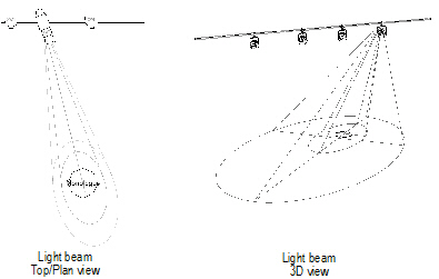
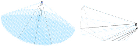
An accurate wireframe representation of the light beam’s spread and location on the stage is drawn, oriented to the focus point. The light beam of instruments used for general wash lighting can also be drawn; however, a focus point is still required in order to draw the light beam representation.
3. Select Draw Beam as 3D Solid from the instrument Object Info palette to see the light beam as a solid cone of light. The Color specified in the Object Info palette or Lighting Device dialog box determines the solid color (see “Lighting Instrument Color” on page 881). The class of the light beam can also determine its appearance and optionally, texture (Renderworks required).
~~~~~~~~~~~~~~~~~~~~~~~~~
 Obtaining
Photometric Data
Obtaining
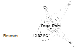
Photometric DataThe Vectorworks Spotlight product can determine and display the surface illumination values of the stage at a specific location (Photometer object) or along a grid (Photometric Grid object).
For photometric values to be measured, the lighting instrument(s) must have a designated focus point.
~~~~~~~~~~~~~~~~~~~~~~~~~
 Inserting
a Photometric Grid
Inserting
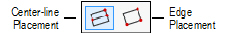
a Photometric Grid The Photometric Grid is a is a three-click rectangular object, and can be inserted in Center-line Placement mode or Edge Placement mode.
Placement Mode |
Description |
|---|---|
Center-line |
Click once, and then again, to define the width through the center of the grid. Click again to specify the width of half the grid. |
Edge |
Click once, and then again, to define the length along the edge of the grid. Click again to specify the grid width. |

To insert a photometric grid:
1. Ensure that each lighting instrument contributing to the illumination is focused.
The light beams do not have to be drawn for calculations to be made.
2. Click the PhotoGrid tool from the Spotlight tool set and click the desired placement mode from the Tool bar.
3. Click in the drawing area to insert the photometric grid.
If this is the first time a photometric grid has been placed on the drawing, the object properties dialog box opens. Specify the preferences to use for this tool during this session, and then click OK.
The photometric grid properties can be changed in the Object Info palette.
Click to show/hide the parameters.
After placing the photometric grid, set the grid’s Z value on the Object Info palette; illumination values vary depending on the grid’s elevation.
~~~~~~~~~~~~~~~~~~~~~~~~~
 Inserting
a Photometer
Inserting
a Photometer 
To insert a photometer:
1. Ensure that each lighting instrument contributing to the illumination is focused.

The light beams do not have to be drawn for calculations to be made.
2. Click the Photometer tool from the Spotlight tool set.
3. Click to place the photometer in the drawing, and click again to set the object’s rotation. If this is the first time the object is placed in the drawing, an object properties dialog box opens. These parameters apply to subsequently created objects; they can be changed later by accessing them from the Object Info palette.
4. Specify the object properties and click OK.
Click to show/hide the parameters.
After placing the photometer, set the its Z value on the Object Info palette; illumination values vary depending on the photometer’s elevation.
~~~~~~~~~~~~~~~~~~~~~~~~~
 Using
Photometric Threshold Settings
Using
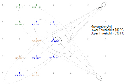
Photometric Threshold SettingsThe photometric grid and photometer calculate and display the illumination values at the elevation point. The values are displayed in either foot candles (Imperial) or lux (Metric), depending on the units selected in File > Document Settings > Units.
If Use Threshold Settings is selected in the Object Info palette, colors indicate the illumination range according to the Lower/Upper Threshold values set in the Object Info palette.
Color |
Description |
|---|---|
Gray |
Illumination value of zero |
Green |
Illumination value between zero and Lower Threshold |
Tan |
Illumination value between Lower and Upper Threshold |
Blue |
Illumination value above Upper Threshold |
The photometric grid and photometer range colors can be changed. See “Customizing Photometric Threshold Colors” on page 904.
To evaluate the illumination values at different heights, change the elevation of the photometric object in the Object Info palette.
~~~~~~~~~~~~~~~~~~~~~~~~~
 Customizing
Photometric Threshold Colors
Customizing
Photometric Threshold ColorsBoth the photometer and photometric grid use colors that correspond to the specified threshold ranges (see “Obtaining Photometric Data” on page 899). These colors can be changed if desired.
To edit the photometric threshold color values:
1. Select Tools > Plug-ins > Plug-in Manager.
The Plug-in Manager opens. Click on the Built-in Plug-ins tab and select either PhotoGrid or Photometer.
2. Click Customize.
The Customize Plug-in dialog box opens. Click on the Strings tab.
3. Select Resource ID “4000: Threshold Color Indices.” Click Edit.
4. The Edit Strings dialog box opens. Select one of the indices and click Edit to specify a new color value for the threshold index.
ID |
Corresponding Threshold Index |
|---|---|
4000 |
Zero level |
4001 |
Levels below the Lower Threshold value |
4002 |
Levels between the Lower and Upper Threshold values |
4003 |
Levels above the Upper Threshold value |
The values correspond to index values of the color palette. For more information on color palette selector values, see the Miscellaneous Selectors section of the developer-oriented documentation located at http://developer.vectorworks.net
5. When the desired threshold index color selector values have been edited, click OK to accept the changes, and then continue to click OK until you can close the Plug-In Manager dialog box.
~~~~~~~~~~~~~~~~~~~~~~~~~
 Inserting
Soft Goods
Inserting
Soft Goods The Soft Goods tool inserts theater and event planning draperies such as curtains, borders, scrims, and pipe-and-drape assemblies. Soft goods objects are drawn along a path, so they can be straight, curved, or in any configuration for total flexibility; the path can be edited after placement. The 3D appearance of soft goods objects can be set for a realistic appearance, or display more schematically. The materials used to create the soft goods configuration can be included in a report for cost estimation (see “Creating Reports” on page 1312). Text labels identify the components of the soft goods object.
~~~~~~~~~~~~~~~~~~~~~~~~~
 Inserting
Curtains and Borders
Inserting
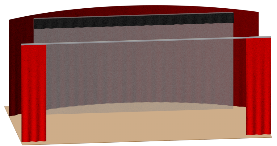
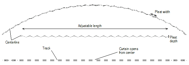
Curtains and Borders The Soft Goods tool creates a curved or straight stage curtain or border. To draw a curtain, either use the Soft Goods tool, or create a polyline and then select the Create Objects from Shapes command (see “Creating Objects from Shapes” on page 273).

To insert a curtain or border:
1. Click the Soft Goods tool from the appropriate tool set:
• Spotlight: Spotlight tool set
• Designer: Detailing tool set
2. Click Preferences from the Tool bar to specify or change any default Soft Goods tool parameters.
The Soft Goods Object Properties dialog box opens.
3. Select either Curtain or Border from the Function list, and specify any other default parameters for this session.
4. Click OK.
5. Click on the appropriate mode in the Tool bar to select the creation method of the soft goods object.
The Corner Vertex or Point on Arc modes are recommended. For more information on the Polyline tool modes, see “Creating Polylines” on page 294.
6. Click to set the soft goods object’s start point.
7. Click to set the end of the segment and the beginning of the next. Continue drawing segments in this manner until the curtain or border object is complete.
Once created, the soft goods object can be reshaped by double-clicking on it. The Reshape tool is automatically activated, to reshape the object directly in the drawing.
The curtain or border parameters can be edited in the Object Info palette. However, certain parameters are not available for borders.
Click to show/hide the parameters.
~~~~~~~~~~~~~~~~~~~~~~~~~
 Inserting
Pipe-and-Drape Assemblies
Inserting
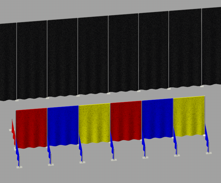
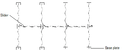
Pipe-and-Drape Assemblies The Soft Goods tool creates pipe-and-drape assemblies typically used in event planning, such as when creating temporary booths in a convention center. To draw a pipe-and-drape assembly, either use the Soft Goods tool, or create a polyline and then select the Create Objects from Shapes command (see “Creating Objects from Shapes” on page 273).

To insert a pipe-and-drape assembly:
1. Click the Soft Goods tool from the appropriate tool set:
• Spotlight: Spotlight tool set
• Designer: Detailing tool set
2. Click Preferences from the Tool bar to specify or change any default Soft Goods tool parameters.
The Soft Goods Object Properties dialog box opens.
3. Select Pipe-and-Drape from the Function list, and specify any other default parameters for this session.
4. Click OK.
5. Click on the appropriate mode in the Tool bar to select the creation method of the soft goods object.
For more information on the Polyline tool modes, see “Creating Polylines” on page 294.
6. Click to set the soft goods object’s start point.
7. Click to set the end of the segment and the beginning of the next. Continue drawing segments in this manner until the pipe-and-drape assembly is complete.
Once created, the soft goods object can be edited by selecting the object, and then selecting Modify > Edit Soft Goods. Reshape the soft goods polyline with the Reshape tool; click Exit Profile to return to the drawing.
The pipe-and-drape assembly parameters can be edited in the Object Info palette.
Click to show/hide the parameters.
To create an opening in the pipe-and-drape assembly, edit the vertex parameters in the Object Info palette. Select the vertex prior to the opening as described in “Editing Vertex-Based Objects” on page 1000, and then click Hide Next Edge.
~~~~~~~~~~~~~~~~~~~~~~~~~
 Setting
Soft Goods 3D Display Options
Setting
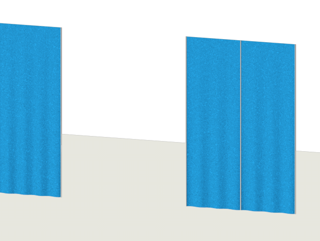
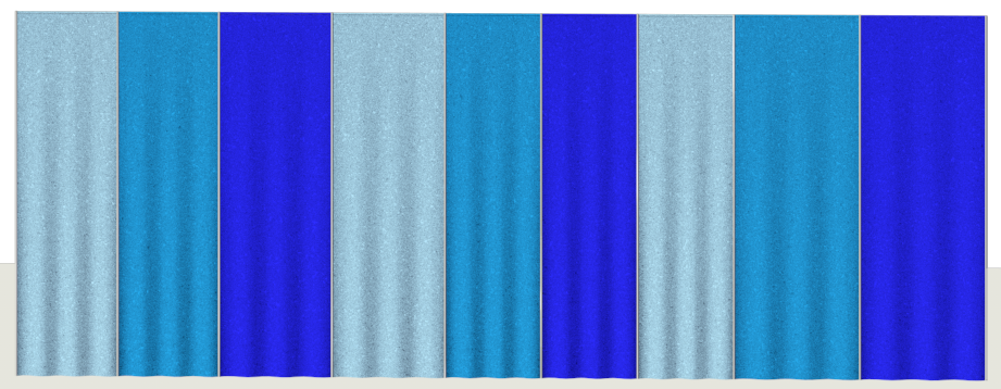
Soft Goods 3D Display Options Select an image texture (Renderworks required) or color to display on the curtain, border, or pipe-and-drape assembly in 3D views. A curtain object can also be made to look like a scrim; pipe-and-drape assemblies can have alternating panel colors. The Vectorworks Spotlight product includes a number of sample image textures, or you can create your own textures (image textures or other textures; see “Creating Textures” on page 1501). The settings made here override any class settings made, if the soft goods object is assigned to a class; an alert dialog box displays if there is a conflict.
To set the 3D display options:
1. Select a curtain, border, or pipe-and-drape assembly. From the Object Info palette, click 3D Curtain Options.
The 3D Curtain Options dialog box opens. Select the display from the Soft Goods Options list and then choose the formatting options.
Click to show/hide the parameters.
2. Click OK.
~~~~~~~~~~~~~~~~~~~~~~~~~
 Formatting
Soft Goods Object Labels
Formatting
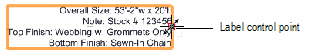
Soft Goods Object Labels A variety of soft goods object labels can be included on the drawing.
To select labels for display and format the text:
1. Select a soft goods object. From the Object Info palette, click Text Options.
The Text Options dialog box opens.
Click to show/hide the parameters.
2. Specify the text label elements and formatting, and then click OK.
Once the label has been added to the drawing, it can be moved by clicking and dragging the label control point (unless Automatically Position Text was selected in the Text Options). Click Default Text Positions from the Object Info palette of a selected soft goods object to restore the text label to its original location.
~~~~~~~~~~~~~~~~~~~~~~~~~
 Inserting
Video Screen Objects
Inserting
Video Screen ObjectsVideo screen objects, such as televisions, projectors, and screens, are often a required part of visualizing a room layout for event planning, and are occasionally needed for theater productions. The Vectorworks Spotlight product automatically helps with the calculations required for placement, image size, and viewing area; it can also display a “glowing” image on the screen for a realistic look (Renderworks required). The video objects can be labeled with calculated information and certain objects display the optimum viewing area.
~~~~~~~~~~~~~~~~~~~~~~~~~
 Inserting
a Television Object
Inserting
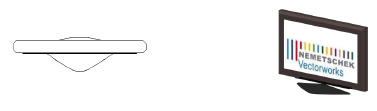
a Television Object The television object simulates CRT and flat screen televisions.

To insert a television:
1. Click the Television tool from the Spotlight tool set.
2. Click once in the drawing to set the object’s position. Click again to set the object’s rotation.
3. If this is the first time a television is placed on the drawing, the object properties dialog box opens. Specify the default preferences, which apply to all televisions placed subsequently in this drawing. Properties can be edited later in the Object Info palette. Click OK.
The television object’s parameters can be edited in the Object Info palette.
Click to show/hide the parameters.
~~~~~~~~~~~~~~~~~~~~~~~~~
 Inserting
an LED Screen
Inserting
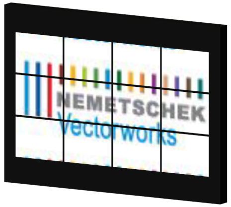
an LED Screen The Light-emitting Diode (LED) object simulates a variety of low-resolution LED screens in arrays on a base structure.

To insert an LED screen or array:
1. Click the LED Screen tool from the Spotlight tool set.
2. Click once in the drawing to set the object’s position. Click again to set the object’s rotation.
3. If this is the first time LED screens are placed on the drawing, the object properties dialog box opens. Specify the default preferences, which apply to all LED screens placed subsequently in this drawing. Properties can be edited later in the Object Info palette. Click OK.
The LED screen parameters can be edited in the Object Info palette.
Click to show/hide the parameters.
~~~~~~~~~~~~~~~~~~~~~~~~~
 Inserting
a Video Screen Object
Inserting
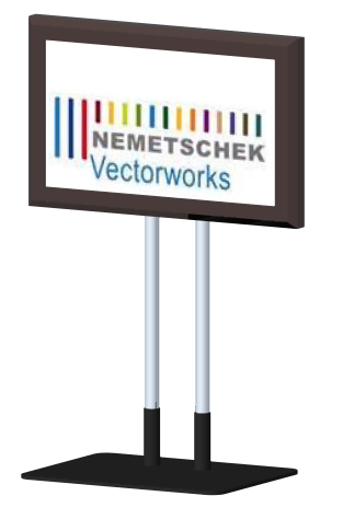
a Video Screen Object Video screen objects consist of a video screen and optional front or rear projector.


To insert a video screen:
1. Click the Video Screen tool from the Spotlight tool set.
2. Click once in the drawing to set the object’s position. Click again to set the object’s rotation.
3. If this is the first time a video screen is placed on the drawing, the object properties dialog box opens. Specify the default preferences, which apply to all video screens placed subsequently in this drawing. Properties can be edited later in the Object Info palette. Click OK.
The height of the video screen and associated projector(s) depends on several factors.
• The Z value entered in the Object Info palette determines the distance from the active layer plane to the bottom of the screen (including the border).
• When the screen includes legs, the legs are drawn on the active layer plane unless a Floor Height value has been specified. The Floor Height distance shifts the floor, and therefore the legs, by that amount from the layer plane.
• Projector stands are inserted relative to both the Vertical Shift and Floor Height values, allowing stands to be shifted up or down from the screen’s floor as set by the Floor Height value.
The video screen object’s parameters can be edited in the Object Info palette.
Click to show/hide the parameters.
~~~~~~~~~~~~~~~~~~~~~~~~~
 Inserting
a Blended Screen and Projector
Inserting
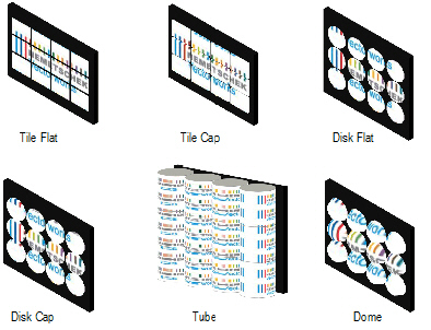
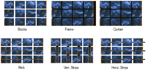
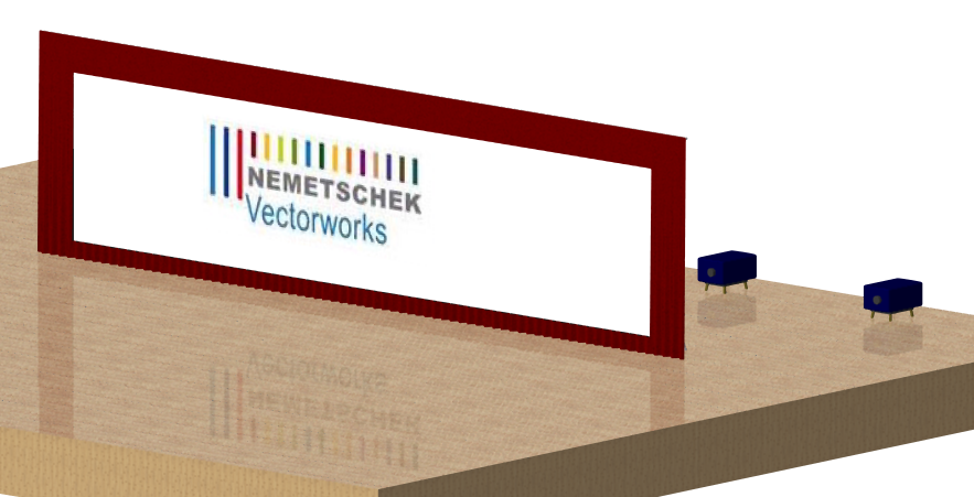
a Blended Screen and Projector The blended screen simulates projection screens that require multiple projectors to produce one large image.

To insert a blended screen and projector(s):
1. Click the Blended Screen tool from the Spotlight tool set.
2. Click once in the drawing to set the object’s position. Click again to set the object’s rotation.
3. If this is the first time a blended screen is placed on the drawing, the object properties dialog box opens. Specify the default preferences, which apply to all blended screens placed subsequently in this drawing. Properties can be edited later in the Object Info palette. Click OK.
When you insert a blended screen, a Blended Screen object is created. Once the parameters of the blended screen and projectors have been set, click Insert Projectors from the Object Info palette to create the projectors associated with that screen. The blended screen settings control the initial projector settings, though each projector can then be set independently (by changing parameters like text position or cone display) if needed. Moving or rotating a blended screen after the projectors have been inserted also moves or rotates the associated projectors.
Use caution when clicking Insert Projectors if projectors have already been inserted; this deletes existing projectors and their parameter settings.
The height of the blended screen and associated projectors depends on several factors.
• The Z value entered in the Object Info palette determines the distance from the active layer plane to the bottom of the screen (including the border).
• When the screen includes legs, the legs are drawn on the active layer plane unless a Floor Height value has been specified. The Floor Height distance shifts the floor, and therefore the legs, by that amount from the layer plane.
• Projector stands are inserted relative to both the Vertical Shift and Floor Height values, allowing stands to be shifted up or down from the screen’s floor as set by the Floor Height value.
The blended screen and blended projector object parameters can be edited in the Object Info palette.
Click to show/hide the parameters.
Click to show/hide the parameters.
~~~~~~~~~~~~~~~~~~~~~~~~~
 Setting the
Image on the Video
Screen
Setting the
Image on the Video
ScreenSelect an image to display on the video screen or LED screen (Renderworks required). The Vectorworks Spotlight product includes a number of sample images, or you can create your own textures. Textures must use an image color shader with constant reflectivity to display on the video screen (see “Creating Textures” on page 1501).
To set the video screen image:
1. Select a video screen object, blended screen, or LED screen object. From the Object Info palette, click Edit Screen Image or Edit Array Image.
The Edit Screen Image or Edit Array Image dialog box opens.
Click to show/hide the parameters.
2. If needed, adjust the image scale, and shift the image horizontally or vertically until it appears correctly in the preview, and then click OK.
~~~~~~~~~~~~~~~~~~~~~~~~~
 Formatting Video Screen Object Labels
A variety of video screen object labels can be included on the drawing. Different options are available depending on the video screen object.
To select labels for display and format the text:
1. Select a video screen object. From the Object Info palette, click Text Options.
The Text Options dialog box opens.
Text Option |
Description |
|---|---|
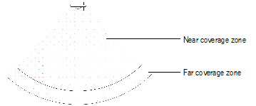
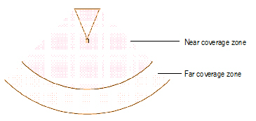
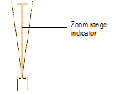
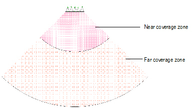
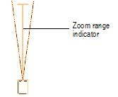
Coverage Zone |
Displays the near and far coverage zone distances and multipliers at the specified text size and color |
Image Dimensions |
Displays the screen image dimensions, and if selected, the image size, screen clearance, and aspect ratio values, at the specified text size, color, and alignment. If desired, the image dimension text order can be changed from the default height x width to width x height instead, by selecting Swap Dimension Order. |
Lens Information |
Displays the projector lens size at the specified text size, color, and alignment |
Projection Distance |
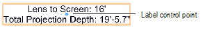
Displays the distance from the projector to the screen at the specified text size, color, and alignment. Select the options to show the straight (plan) distance in 2D, direct distance (projector throw distance) in 2D, and/or actual distance in 3D. A dimension line can be included; specify the marker size. |
Projector IDs |
Labels the projector body with the entered ID information (such as projector name), at the specified text size and color. Any Note text is not displayed, but stores internal information about the projector. |
Multiple Projector Note |
Displays the multiple projector layout for stacked projectors at the specified text size and color |
Show Array Dimensions |
For LED screen arrays, displays the overall array dimensions and total number of modules at the specified text size, color, and alignment |
Note |
Show the text entered for Note in the Object Info palette of the video screen object, at the specified text size, color, and alignment. A Note Label prefix can also be included; enter the contents of the prefix. |
Keep Text Horizontal |
Maintains the text in a horizontal position even when the object is rotated; deselect this option to rotate the label along with the object |
Fill Text Background |
Allows a text background fill to be used for all video screen text; by default, white is used as the fill color. To specify a different fill color, select the Object Info palette option to class the parts of the video screen object, and then select a fill color for the class of the video screen text. The class should be set to Use at Creation. |
2. Specify the text labels and formatting, and then click OK.
Once the labels have been added to the drawing, they can be moved by clicking and dragging the label control point. Click Default Text Positions from the Object Info palette of a selected video object to restore the text labels to their original locations.
~~~~~~~~~~~~~~~~~~~~~~~~~
 Inserting
Speakers and Speaker Arrays
Inserting
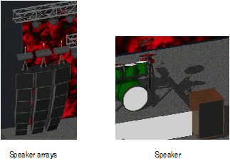
Speakers and Speaker ArraysAudio objects, including speakers and arrays of speakers, are often a required part of visualizing a room or stage layout for event planning and entertainment design, and can also be needed for theater productions. The Vectorworks Spotlight product creates speaker system layout drawings and can perform basic audio coverage analysis. The speakers and speaker arrays can be labeled with information and calculated data and can display the optimum listening area for up to three ranges.
The Vectorworks Spotlight software comes with default speaker data located in the audio tools folders of the [Vectorworks]\Libraries folder that is included with the Vectorworks Spotlight product (see “Resource Libraries” on page 215). You can also save speaker data to a library file, which can be shared with others, and you can import speaker data from other files. The file(s) must be located within the Audio Tools\Speakers or Audio Tools\Bumpers folders.
Another way to share speakers or speaker arrays is to create symbols from them and import the symbol into another file.
~~~~~~~~~~~~~~~~~~~~~~~~~
 Inserting
Speakers
Inserting
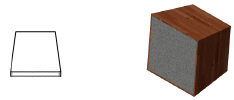
Speakers Individual speakers that are not part of an array are inserted with the Speaker tool. Manually-inserted speakers can be placed as single speakers, or as several speakers arranged in a column. A variety of supports and labeling options are available. Use a speaker type and information with pre-set data from the speaker library file located in the [Vectorworks]\Libraries folder that is included with the Vectorworks Spotlight product (see “Resource Libraries” on page 215), or create a speaker with custom data and save it to the library for future use and sharing.

To insert a speaker:
1. Click the Speaker tool from the Spotlight tool set.
2. Click once in the drawing to set the object’s position. Click again to set the object’s rotation.
3. If this is the first time a speaker is placed on the drawing, the object properties dialog box opens. Specify the default preferences, which apply to all speakers placed subsequently in this drawing. Properties can be edited later in the Object Info palette. Click OK.
The speaker object’s parameters can be edited in the Object Info palette.
Click to show/hide the parameters.
~~~~~~~~~~~~~~~~~~~~~~~~~
 Inserting
Speaker Arrays
Inserting
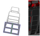
Speaker Arrays Large venues require the use of speaker arrays, which consist of speakers stacked in a column and topped by a bumper (top mounting bracket). Up to three different types of speakers can be included in an array. The speakers can each be tilted differently to provide maximum audio coverage for the audience.

To insert a speaker array:
1. Click the Speaker Array tool from the Spotlight tool set.
2. Click once in the drawing to set the object’s position. Click again to set the object’s rotation.
3. If this is the first time a speaker array is placed on the drawing, the object properties dialog box opens. Specify the default preferences, which apply to all arrays placed subsequently in this drawing. Properties can be edited later in the Object Info palette. Click OK.
4. A bumper is inserted on the drawing. From the Object Info palette, click Configure Array.
The Array Detail and Configuration dialog box opens. Specify the bumper parameters on the Bumper tab.
Click to show/hide the parameters.
5. On the Speaker A, B, and C tabs, configure up to three types of speakers for inclusion in the array. If speaker B and/or C are not to be included, select a Type of None on those tabs.
Click to show/hide the parameters.
6. Set up the array configuration on the Array tab.
Click to show/hide the parameters.
7. Click OK to create the speaker array. From the Object Info palette, click Insert Speakers to add the speakers to the drawing.
The speaker array properties can be edited in the Object Info palette. To edit the array, select the bumper. Individual speakers can be selected and certain parameters can be set independently, but since the speakers are controlled by the array, many of their parameters are not available (see “Inserting Speakers” on page 931 for parameter descriptions).
Click to show/hide the parameters.
~~~~~~~~~~~~~~~~~~~~~~~~~
 Formatting
Speaker Object Labels
Formatting
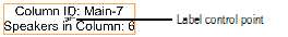
Speaker Object Labels A variety of speaker and speaker array labels can be included on the drawing. Different options are available for speakers and speaker arrays. A speaker array, as well as the individual speakers that make up the array, can be labeled.
To select labels for display and format the text:
1. Select a speaker or speaker array object (bumper). From the Object Info palette, click Text Options.
The Text Options dialog box opens.
Click to show/hide the parameters.
2. Specify the text label elements and formatting, and then click OK.
Once the label has been added to the drawing, it can be moved by clicking and dragging the label control point. Click Default Text Position from the Object Info palette of a selected speaker or array object to restore the text label(s) to the original location.
~~~~~~~~~~~~~~~~~~~~~~~~~
 Inserting a Stage Lift
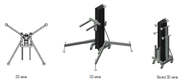
A stage lift object can be added to a Vectorworks Spotlight drawing to represent the typical adjustable support device commonly found on stage for supporting speakers, trusses, and other stage equipment. The stage lift can be shown extended or collapsed, with a specific appearance and fork position, and can be labeled.

To insert a stage lift:
1. Click the Stage Lift tool from the Spotlight tool set.
2. Click once in the drawing to set the object’s position. Click again to set the object’s rotation.
3. If this is the first time a stage lift is placed on the drawing, the object properties dialog box opens. Specify the default preferences, which apply to all stage lifts placed subsequently in this drawing. Properties can be edited later in the Object Info palette. Click OK.
The stage lift parameters can be edited in the Object Info palette.
Click to show/hide the parameters.
~~~~~~~~~~~~~~~~~~~~~~~~~
 Formatting
Stage Lift Labels
Formatting
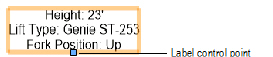
Stage Lift Labels A variety of stage lift labels can be included on the drawing. Text must be entered into the associated field of the Object Info palette for the label to be included.
To select labels for display and format the text:
1. Select a stage lift object. From the Object Info palette, click Text Options.
The Text Options dialog box opens.
Click to show/hide the parameters.
2. Specify the text label elements and formatting, and then click OK.
Once the label has been added to the drawing, it can be moved by clicking and dragging the label control point. Click Default Text Position from the Object Info palette of a selected stage lift object to restore the text label(s) to the original location.
~~~~~~~~~~~~~~~~~~~~~~~~~
 Inserting Stage Structures
The Vectorworks Spotlight product includes several different types of rectangular, round, and free form stage structures, along with the specialized, industry standard steps and ramps to access them. These theatrical and event staging structures can range from simple, basic forms to complex structures with customized textures for a realistic appearance (Renderworks required). The event design commands also make use of these structures.
~~~~~~~~~~~~~~~~~~~~~~~~~
 Inserting
a Stage Deck
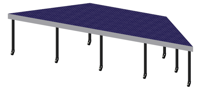
Inserting
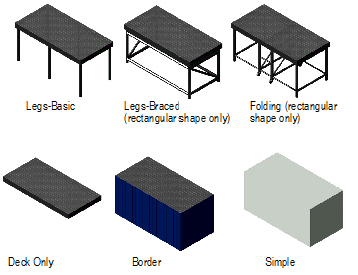
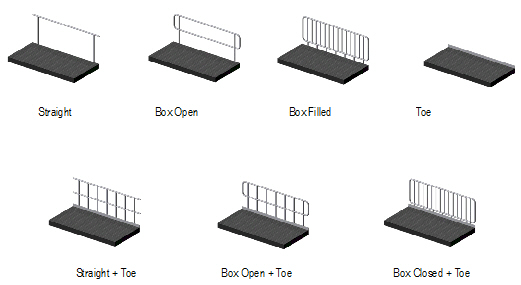
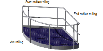
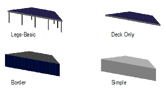
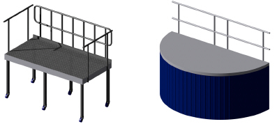
a Stage DeckThe Stage Deck tool inserts rectangular and rounded portable stage structures into a Vectorworks Spotlight drawing. The type, shape, size, appearance, and presence of railings can be customized. Place several stage decks to create a large stage area.

To insert a stage deck:
1. Click the Stage Deck tool from the Spotlight tool set.
2. Click once in the drawing to set the object’s position. Click again to set the object’s rotation.
3. If this is the first time a stage deck is placed on the drawing, the object properties dialog box opens. Specify the default preferences, which apply to all stage decks placed subsequently in this drawing. Properties can be edited later in the Object Info palette. Click OK.
The stage deck parameters can be edited in the Object Info palette.
Click to show/hide the parameters.
~~~~~~~~~~~~~~~~~~~~~~~~~
 Inserting
a Stage Plug
Inserting
a Stage PlugThe Stage Plug tool inserts custom shaped stage structures into a Vectorworks Spotlight drawing. The type, shape, size, and appearance can be customized.

To insert a stage plug:
1. Click the Stage Plug tool from the Spotlight tool set.
2. Click on the appropriate mode in the Tool bar to select the boundary creation method of the stage.
For more information on the Polyline tool modes, see “Creating Polylines” on page 294.
3. Click to set the stage’s start point.
4. Click to set the end of the segment and the beginning of the next. Continue drawing segments in this manner until the stage object is complete.
5. If this is the first time a stage plug is placed on the drawing, the object properties dialog box opens. Specify the default preferences, which apply to all stage plugs placed subsequently in this drawing. Properties can be edited later in the Object Info palette. Click OK.
The stage plug can be reshaped with the Reshape tool; see “Remodelando Objetos” on page 1041. The stage plug parameters can be edited in the Object Info palette.
Click to show/hide the parameters.
~~~~~~~~~~~~~~~~~~~~~~~~~
 Formatting
Stage Labels
Formatting
Stage LabelsA variety of stage labels can be included on the drawing. For some options, text must be entered into the associated field of the Object Info palette for the label to be included.
To select labels for display and format the text:
1. Select a stage deck or stage plug object. From the Object Info palette, click Text Options.
The Text Options dialog box opens.
Click to show/hide the parameters.
2. Specify the text label elements and formatting, and then click OK.
Once the label has been added to the drawing, it can be moved by clicking and dragging the label control point. Click Default Text Position from the Object Info palette of a selected stage object to restore the text label(s) to the original location.

~~~~~~~~~~~~~~~~~~~~~~~~~
 Inserting
Stage Steps
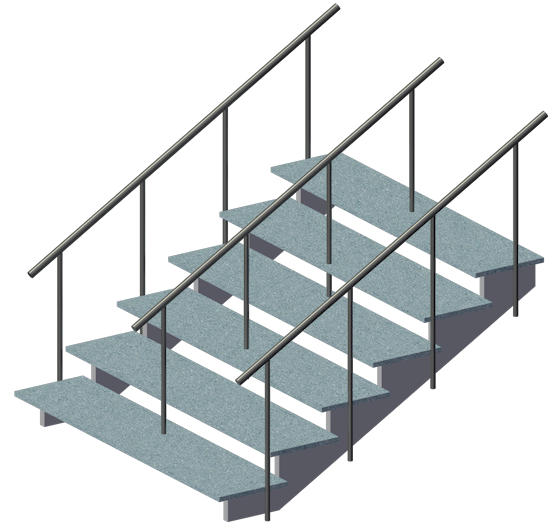
Inserting
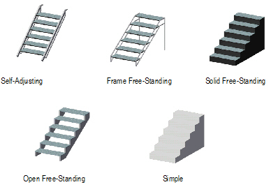
Stage StepsThe Stage Steps tool inserts portable steps typically used with temporary stage structures into a Vectorworks Spotlight drawing. The type, shape, size, appearance, and presence of railings can be customized.

To insert stage steps:
1. Click the Stage Steps tool from the Spotlight tool set.
2. Click once in the drawing to set the object’s position. Click again to set the object’s rotation.
3. If this is the first time a set of stage steps is placed on the drawing, the object properties dialog box opens. Specify the default preferences, which apply to all stage steps placed subsequently in this drawing. Properties can be edited later in the Object Info palette. Click OK.
The stage step parameters can be edited in the Object Info palette.
Click to show/hide the parameters.
~~~~~~~~~~~~~~~~~~~~~~~~~
 Formatting
Stage Step Labels
Formatting
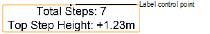
Stage Step LabelsA variety of stage step labels can be included on the drawing. For some options, text must be entered into the associated field of the Object Info palette for the label to be included.
To select labels for display and format the text:
1. Select a stage steps object. From the Object Info palette, click Text Options.
The Text Options dialog box opens.
Click to show/hide the parameters.
2. Specify the text label elements and formatting, and then click OK.
Once the label has been added to the drawing, it can be moved by clicking and dragging the label control point. Click Default Text Position from the Object Info palette of a selected stage steps object to restore the text label(s) to the original location.
~~~~~~~~~~~~~~~~~~~~~~~~~
 Inserting
a Stage Ramp
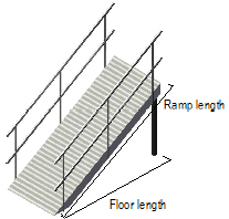
Inserting
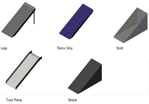
a Stage RampThe Stage Ramp tool inserts the type of portable ramp typically used with temporary stage structures into a Vectorworks Spotlight drawing. The type, shape, size, appearance, and presence of railings can be customized.

To insert a stage ramp:
1. Click the Stage Ramp tool from the Spotlight tool set.
2. Click once in the drawing to set the object’s position. Click again to set the object’s rotation.
3. If this is the first time a stage ramp is placed on the drawing, the object properties dialog box opens. Specify the default preferences, which apply to all stage ramps placed subsequently in this drawing. Properties can be edited later in the Object Info palette. Click OK.
The stage ramp parameters can be edited in the Object Info palette.
Click to show/hide the parameters.
~~~~~~~~~~~~~~~~~~~~~~~~~
 Formatting
Stage Ramp Labels
Formatting
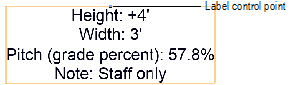
Stage Ramp LabelsA variety of stage ramp labels can be included on the drawing. For some options, text must be entered into the associated field of the Object Info palette for the label to be included.
To select labels for display and format the text:
1. Select a stage steps object. From the Object Info palette, click Text Options.
The Text Options dialog box opens.
Click to show/hide the parameters.
2. Specify the text label elements and formatting, and then click OK.
Once the label has been added to the drawing, it can be moved by clicking and dragging the label control point. Click Default Text Position from the Object Info palette of a selected stage ramp object to restore the text label(s) to the original location.
~~~~~~~~~~~~~~~~~~~~~~~~~