 Lighting Symbol Maintenance Lighting Symbol Maintenance
 Manage, edit, and update the symbols and data for all the lighting symbols in the file from a single location. Easily spot inconsistencies and missing data, and fix the issues for all existing symbols or just for future symbol placement.
To maintain the data and symbols for all the lighting symbols in the file:
1. Select Spotlight > Reports > Lighting Symbol Maintenance.
The Lighting Symbol Maintenance dialog box opens.
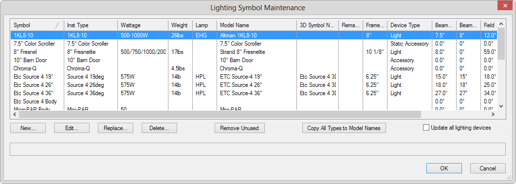
Click to show/hide the parameters.
2. When finished with lighting symbol maintenance tasks, click OK.
3. If any lighting instrument data has changed, but Update all lighting devices was not selected, an alert message displays.
Click Yes to update all existing and future symbol instances in the file. Select No to update only future symbol instances.
 Lighting Inventory Setup
The current status of available lighting device inventory is specified with the Lighting Inventory Setup command. The number of available devices can be included in instrument summaries.
To establish and maintain inventory counts:
1. Select Spotlight > Reports > Lighting Inventory Setup.
The Lighting Inventory Setup dialog box opens.
2. Select each device type row, and enter the number of available instruments in the Quantity.
The devices can be sorted by clicking in the Type column header.
3. Click OK.
The inventory report can be included as a report when generating paperwork.
~~~~~~~~~~~~~~~~~~~~~~~~~
 Creating Instrument Summaries
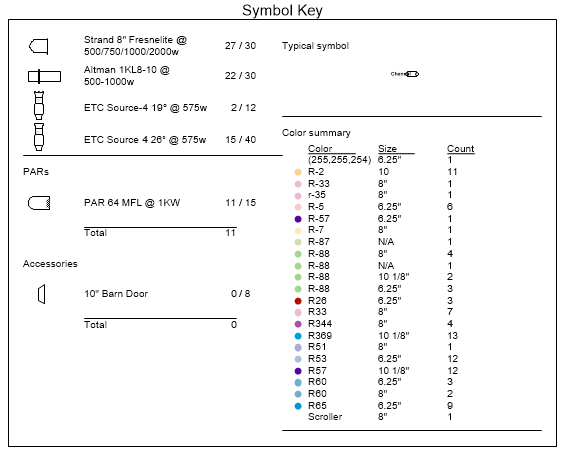
Statistics on the instruments and accessories used in the light plot help with show organization. Instrument summaries can be created for the all instruments (see “Creating an Instrument Summary” on page 961), and/or for specific lighting positions (see “Creating an Instrument Summary for a Lighting Position” on page 966). The summary, which can be custom formatted, can show the symbol thumbnail and name, the number of each kind of instrument and accessories in use, display total counts, and add special elements like notes, column breaks, circuit summaries, typical label legend layout, and other items. Counting can be subtotaled to count instrument bodies and lenses. Symbols which have the same instrument type are counted together, allowing for alternate versions of a single type. The summary can compare its information to the current inventory so that the designer can determine how many instruments remain in the inventory, or whether more instruments have been specified than are currently present in the inventory.
~~~~~~~~~~~~~~~~~~~~~~~~~
 Creating
an Instrument Summary
Creating
an Instrument Summary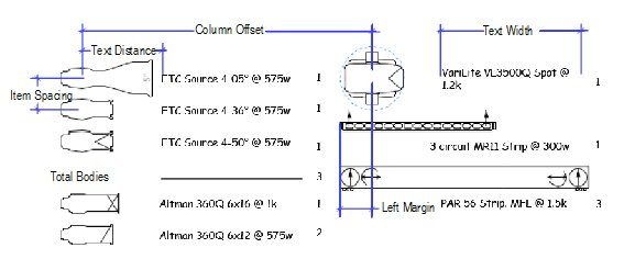

To create an instrument summary:
1. Click the Instrument Summary tool from the Spotlight tool set.
2. Click Preferences from the Tool bar.
The Instrument Summary Settings dialog box opens. Default parameter settings made here, both for global instrument summaries and lighting position summaries, apply to instrument summaries placed later in the file. These default sets are saved separately and are in effect depending on how the summary is inserted. Taking the time to establish the defaults makes it much easier to insert summaries for lighting positions or for the entire drawing with the desired defaults already specified.
Click to show/hide the parameters.
3. Click Build List to select the elements to be included in the summary.
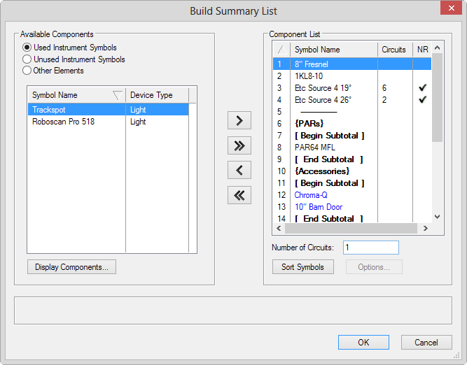
The Build Summary List dialog box opens, to specify what is listed in the summary. You can add instrument symbols in use, instrument symbols present in the file (but not currently in the drawing), and formatting elements such as column headers, notes, and circuit summaries.
Click on each type of component and move the desired elements to the Component List. To change the order, click in the first column and drag the item to the desired position in the list, or click Sort Symbols to sort them alphabetically.
Click to show/hide the parameters.
4. If you have included other elements that require formatting, select each one from the Component List and click Options.
• For headers, position height headers, or notes, enter the header or note text.
• For typical symbol, select the symbol to indicate labels (usually a label legend symbol, located within the Label Legend symbol folder)
• For circuit summaries, the Circuit Summary Options dialog box opens to specify the circuit information to include in a lighting position summary. Specify the types of devices to count and how to count them, and enter the device amperage rating/voltage to obtain a report indicating the circuit type you will need for those devices.
Click to show/hide the parameters.
5. Click OK to return to the Build Summary List; continue specifying summary list options.
6. Click OK to close the Build Summary List dialog box and return to the Instrument Summary Settings dialog box.
7. Click OK.
8. Click in the drawing to place the instrument summary. Click again to set the rotation.
The instrument summary parameters can be edited from the Object Info palette. However, the Summary Defaults for option is not available since the summary already exists for instruments or lighting positions.
Filtering and refreshing are options that are available from the Object Info palette after an instrument summary has been added to the drawing.
Click to show/hide the parameters.
~~~~~~~~~~~~~~~~~~~~~~~~~
 Creating
an Instrument Summary for a Lighting Position
Creating
an Instrument Summary for a Lighting PositionAn instrument summary can be created for a lighting position rather than for the entire drawing.
To create an instrument summary for a selected lighting position:
1. Select the lighting position.
2. From the Object Info palette, click Insert Position Summary.
3. A position summary is added next to the lighting position.
If a summary build list has never been specified in the file, a placeholder labeled Build List is placed instead, indicating that a build list has not yet been specified in the file and needs to be set.
The position summary uses the Summary Defaults for parameters for a position, as set up in the instrument summary settings, and the summary is filtered for the current lighting position. As instruments are added to the position, click Insert Position Summary to add the instruments to the end of the summary. To change specific instrument summary parameters, select the instrument summary and edit the parameters in the Object Info palette as described in “Creating an Instrument Summary” on page 961.
If you delete a lighting position, the associated instrument summary is also deleted.
~~~~~~~~~~~~~~~~~~~~~~~~~
 Filtering Instrument Summary Contents
Instrument summaries can be filtered to limit the contents by lighting position, layer, class, or specified criteria.
To filter the instrument summary contents:
1. Select an instrument summary.
2. From the Object Info palette, click Filters.
The Summary Filters dialog box opens. Each tab includes filtering options to limit the summary contents according to specified criteria. The selections made on each tab are additive.
Click to show/hide the parameters.
3. Click OK.
The summary list is filtered. The Active Filters in the Object Info palette displays the current filters and/or criteria string.
~~~~~~~~~~~~~~~~~~~~~~~~~
 Generating
Paperwork
Generating
Paperwork The information to be included in the various schedules and reports, as well as the format of the reports, is specified in the Generate Paperwork dialog box.
The Choose Schedule command automatically creates certain reports as preformatted worksheets; see “Creating Schedules Automatically” on page 1314.
To set up the schedule and report information:
1. Select Spotlight > Reports > Generate Paperwork.
The Generate Paperwork dialog box opens.
2. Select the desired Schedules and Reports. Each schedule and report selected must be set up by clicking on its Setup button. The setup procedure is described in the following sections.
3. Configure the rest of the paperwork setup by entering the Header Configuration, Show Information and the Page Properties. Click OK to generate the desired paperwork with the specified settings.
~~~~~~~~~~~~~~~~~~~~~~~~~
 Schedule Setup
The information to be included in the various schedules, as well as the format of the schedules, is specified in the Schedule Formatting dialog box.
To set up the schedule contents and formatting:
1. Select Spotlight > Reports > Generate Paperwork. The Generate Paperwork dialog box opens.
2. Click the Setup button under the Schedules list. The Schedule Formatting dialog box opens.
Each schedule in the Schedule list is formatted in the same way. The formatting must be specified for each schedule by first selecting the schedule from the list and then specifying the format.
When selecting Available fields and Column Order, press and hold the Shift key to select multiple, contiguous items or press and hold the Ctrl key (Windows) or Command key (Mac) to select non-contiguous items.
Click to show/hide the parameters.
3. After specifying the column information, order, and width, as well as the page formatting for each type of schedule to be generated, click OK to return to the Generate Paperwork dialog box. The schedule formatting is used when the paperwork is generated.
The Schedule formatting settings are saved in the file’s Schedule Formats worksheet. The worksheet, and all the formatting, can be imported into another file through the Resource Browser.
~~~~~~~~~~~~~~~~~~~~~~~~~
 Inventory Reports
An inventory report, showing the items currently placed on the light plot and the items available, can be included in the generated paperwork. The inventory report can be set up from the Generate Paperwork dialog box, or from the Spotlight > Lighting Inventory Setup command.
To include an inventory report:
1. Select Spotlight > Reports > Generate Paperwork, and then select Inventory from the Generate Paperwork dialog box. To create an inventory report that will separate instrument information according to lighting position, select Break Down by Position.
2. Click the Setup button next to Inventory. The Lighting Inventory Setup dialog box opens.
3. Select each device type row, and enter the number of available instruments in the Quantity.
The devices can be sorted by clicking in the Type column header.
4. Click OK to close the Lighting Inventory Setup dialog box and return to the Generate Paperwork dialog box.
~~~~~~~~~~~~~~~~~~~~~~~~~
 Magic
Sheets
Magic
SheetsMagic sheets are graphical representations of instruments on the plot; they can be broken down either by focus point or color. Magic sheets are invaluable for cueing a show. They are simple to set up and generate in the Vectorworks Spotlight product.
To create a magic sheet:
1. Select Spotlight > Reports > Generate Paperwork, and then select Magic Sheets in the Generate Paperwork dialog box.
2. Click the Setup button next to Magic Sheets. The Magic Sheet Setup dialog box opens. Specify the magic sheet setup parameters.
Action |
Description |
|---|---|
Generates the magic sheets with lighting summarized by color |
Click Color; each instrument of a particular color is shown in one view. The general Theatre Style needs to be selected from the list to be used as a reference for the color summaries. |
Generates the magic sheets with lighting summarized by focus area |
Click Area. All instrumentation that has a specified focus point will be included in the report. If desired, the magic sheet color number value can be displayed in an approximation of its gel color. Select Show Color Name in color. |
The Theatre Styles are editable symbols. Custom styles can be added into the file’s Theater Types folder using the Resource Browser.
3. Click OK to close the Magic Sheet Setup dialog box and return to the Generate Paperwork dialog box.
~~~~~~~~~~~~~~~~~~~~~~~~~
 Color
Cut List
Color
Cut ListA color cut list shows all the colors required by the show, and calculates the number of each cut size required per color.
To create a color cut list:
1. Select Spotlight > Reports > Generate Paperwork and then select Color Cut List in the Generate Paperwork dialog box.
2. If desired, select Break Down by Position to further break the color cut list down by lighting position.
~~~~~~~~~~~~~~~~~~~~~~~~~
 Header Configuration
In the Generate Paperwork dialog box, select the position of the header information specified in Show Information. For the Left, Center, and Right header positions, select the information to be displayed from the list (Designer, Show Name, and/or Date). If no header information is desired for the location, select None.
~~~~~~~~~~~~~~~~~~~~~~~~~
 Show
Information
Show
InformationIn the Generate Paperwork dialog box, enter the name of the lighting Designer and the Show Name, if desired. Type the date of the show or event. To use today’s date, click Date.
~~~~~~~~~~~~~~~~~~~~~~~~~
 Page
Properties
Page
PropertiesIn the Generate Paperwork dialog box, enter the Page Height and Page Width values in the default file units. These values specify the print area (page width with printer margins). The width of the schedule columns is affected by this value.
If desired, a different unit can be used by specifying the value and the unit. For example, even if the default file units are centimeters, specify eight inches for the Page Properties by entering 8". Click OK to generate the selected schedules and reports in the format specified.
~~~~~~~~~~~~~~~~~~~~~~~~~
 Reviewing
Generated Paperwork
Reviewing
Generated PaperworkOnce the paperwork has been formatted and generated, it can be checked and printed.
If Magic Sheets were generated, a new design layer is added to the file. Depending on the type of Magic Sheet generated, the new design layer is called Magic Sheet-Area or Magic Sheet-Color. The magic sheets are placed on this design layer, and formatted to the specified page size (select View > Zoom > Fit to Window if the Magic Sheet items cannot be seen). If the light plot parameters are changed, the magic sheets must be regenerated to reflect the updates.
The specified reports and schedules, once generated, display in the Resource Browser under the Worksheets heading of the current file.
For more information on worksheets, see “Worksheets” on page 1311.
The following points should be remembered when working with generated paperwork:
• Edits to this type of worksheet do not update the light plot parameters.
• If the light plot parameters are edited, this type of report or schedule must be regenerated to reflect the updates.
 Creating
Hanging Cards
Creating
Hanging CardsLighting position hanging cards can be created in the Vectorworks Spotlight product.
To create hanging cards:
1. Set the design layer visibility by selecting Window > Palettes > Navigation and clicking the Design Layers tab. Set only the design layers with the desired lighting positions and instruments to visible.
2. Similarly, set class visibility by clicking the Classes tab and setting only the desired classes to visible.
3. Select View > Create Viewport.
The Create Viewport dialog box opens. For more information on viewports, see “Creating Sheet Layer Viewports” on page 1612.
4. From the Create on Layer field, select the sheet layer for the viewport (or create a new sheet layer).
5. Select Display Planar Objects and Project Screen Objects, with Top/Plan view and Wireframe rendering. Click OK.
6. The viewport is created and the sheet layer displays.
7. Select Modify > Edit Viewport.
The Edit Viewport dialog box opens. Select Crop and click OK.
Alternatively, right-click (Windows) or Ctrl-click (Mac) the viewport and select Edit Crop from the context menu to crop the viewport.
8. In crop viewport mode, draw a 2D shape to crop the desired lighting position.
To hide the cropping shape, set its line thickness to zero in the Attributes palette. Click Exit Viewport Crop at the top right of the drawing window to crop the viewport.
9. The cropped viewport displays on the sheet layer.
10. Several viewports can be created on the same sheet layer to display all the desired hanging cards. Changes to the design layer(s) are automatically reflected in the viewport.
11. Add lighting position summaries to the sheet layer as described in “Creating an Instrument Summary for a Lighting Position” on page 966; adjust the Scale of the displayed symbols so that they do not display at a 1:1 scale, but are sized appropriately for the sheet layer.
 Inserting Gobo Projections
A pattern, texture, or color can be placed on a lighting instrument and projected onto the stage. This special light source and instrument combination is a gobo projection.
Lighting instruments with gobo projections cast a light beam that can be rendered by the Renderworks product. You can then preview the effect of the gobo projection texture(s) on the stage.
The Renderworks product must be installed to render gobo projections. For more information on rendering, see “Rendering the Drawing” on page 1565.
~~~~~~~~~~~~~~~~~~~~~~~~~
 Gobo
Texture Libraries
Gobo
Texture LibrariesThe Vectorworks Spotlight product includes thousands of commercial gobo textures from Apollo, Lee, GAM, GOBOLAND, High End Systems, and Rosco. Through the Resource Browser, import the texture into the current file from one of the files located in the gobo textures folder of the [Vectorworks]\Libraries folder that is included with the Vectorworks Spotlight product (see “Resource Libraries” on page 215). To use the texture in a gobo projection, specify its name in the Object Info palette (see “Creating Gobo Textures” on page 974).
When the Vectorworks Spotlight product is installed, gobo textures are also provided as default content (default content is automatically imported into the file when selected while changing instrument properties, and displays in the Resource Browser; see “Editing Lighting Instruments” on page 876, and “Resource Libraries” on page 215.)
 Inserting
a Gobo Projector
Inserting
a Gobo ProjectorA gobo projector is a lighting instrument with a light source and gobo projector specified.
1. Insert a lighting instrument as described in “Inserting Instruments” on page 874.
2. In the Object Info palette of the selected instrument, click Edit.
The Lighting Device dialog box opens. This provides a convenient way of specifying parameters (see “Changing Instrument Properties” on page 879), although the parameters can also be entered directly in the Object Info palette.
3. On the Instrument Properties tab, specify a focus point for the instrument.
4. For Gobo 1, enter the name of the gobo projection texture (if it has been imported into the file as a resource), or click Get Resource to select a gobo texture from the default content. Specify the Gobo 1 Rotation angle, if any.
5. If there is a second gobo texture, specify its parameters in Gobo 2.
6. Click OK.
7. Turn on the embedded light source for the lighting instrument.
Either right-click on the light, and select Edit Light from the context menu to open the Properties dialog box (and click On), or turn on the light from the Visualization palette.
To preview the effect of a color projection on the stage, indicate the Color name in the Object Info palette of a selected instrument, without specifying a gobo texture. Render the gobo projection to project the light on the focus point with the specified color. The colors can be selected from the color libraries installed with the Vectorworks Spotlight product. The color code must be entered in a “Manufacturer color value” format (for example, R101). If the color value cannot be found, the color defaults to white.
~~~~~~~~~~~~~~~~~~~~~~~~~
 Creating
Gobo Textures
Creating
Gobo Textures In addition to the gobo images available in the pre-defined commercial gobo projection libraries, any square image can be converted into a gobo projection texture.
The Renderworks product must be installed in order to create gobo textures.
Most image-based textures are automatically compressed when imported into a Vectorworks file. Imported JPEG files retain the original JPEG data; all other image files are compressed using lossless PNG format.
To create a gobo texture:
1. Select Spotlight > Visualization > Create Gobo Texture.
The Create Gobo Texture dialog box opens.
Click to show/hide the parameters.
For more information on editing textures, see “Editing Textures and Shaders” on page 1512.
2. Click OK.
If a resource with an image is already present in the file, the Choose Image dialog box opens.
Click to show/hide the parameters.
3. Select the desired image file and click Open.
4. If Edit Texture was selected in Step 1, the Edit Texture dialog box opens. Select the desired options and click OK. Click OK again to close the Create Gobo Texture dialog box.
The texture resource is created and is listed in the Resource Browser.
5. Associate a defined texture with an instrument by entering the texture name in the Gobo 1 or Gobo 2 field of a selected instrument’s Object Info palette, and specify the Gobo Rotation, if any.
A texture can be saved in the default content file located in gobo textures folder of the [Vectorworks]\Libraries folder that is included with the Vectorworks Spotlight product (see “Resource Libraries” on page 215). Import the texture into the default file, or save a new default file within the folder.
~~~~~~~~~~~~~~~~~~~~~~~~~
 Editing
Gobo Texture Transparency Settings
Editing
Gobo Texture Transparency SettingsA gobo texture is a transparent image resource listed in the Resource Browser. The transparency settings can be edited after the gobo image has been specified, or at creation.
To edit a created gobo texture’s transparency:
1. Select the resource in the Resource Browser.
2. Select Resources > Edit to open the Edit Texture dialog box. The Image Transparency settings can be edited. For more information on editing textures, see “Editing Textures and Shaders” on page 1512.
The texture Size must be 2 inches.

~~~~~~~~~~~~~~~~~~~~~~~~~
 Showing
Gobo Projections
Showing
Gobo ProjectionsThe gobo textures and color of a selected light instrument can be projected in a rendered simulation. This rendered image allows you to preview the effect of the gobo texture.
~~~~~~~~~~~~~~~~~~~~~~~~~
 Gobo
Projection Requirements
Gobo
Projection RequirementsTo be able to project a gobo texture, the lighting instrument must:
• Have one or two gobo textures specified
• Be aimed at an existing focus area specified in the Focus field of the Object Info palette
• Have its associated light source turned on (either right-click on the light, and select Turn On from the context menu, or turn on the light from the Visualization palette)
• Have Draw Beam deselected in the Object Info palette
The following Vectorworks software requirements must be met:
• The design layer containing the instrument with gobo texture must also contain 3D geometry (any 3D object that is capable of accepting a Renderworks light) to project the texture
• The Renderworks product must be installed
• Either Fast Renderworks or Custom Renderworks can be used
For Custom Renderworks, at a minimum, Shadows and Textures must be selected in the custom Renderworks settings.
To select the custom settings, select View > Rendering > Custom Renderworks Options. For more information on Custom Renderworks settings, see “Custom Renderworks Options” on page 1596.
~~~~~~~~~~~~~~~~~~~~~~~~~
 Projecting
a Gobo Texture
Projecting
a Gobo TextureTo project a gobo texture:
1. Make all the settings and meet all the requirements described in the previous sections (see “Inserting a Gobo Projector” on page 973, and “Gobo Projection Requirements” on page 976).
2. Select View > Rendering > Custom Renderworks.
~~~~~~~~~~~~~~~~~~~~~~~~~
 Managing Scenes
 The levels, colors, positions, and focusing of all the instrument objects can be saved as a lighting scene. The scenes can then be used to create movies of the scene transitions.
~~~~~~~~~~~~~~~~~~~~~~~~~
 Saving
Scenes
Saving
Scenes To save a scene:
1. After the lighting properties for all the instruments have been set correctly, select Spotlight > Visualization > Manage Scenes. The Manage Scenes dialog box opens.
2. In the Scenes list, the list of saved scenes is displayed. The scenes are sorted by the order in which they are entered. To save the current settings as a scene, click Save. The Save dialog box opens.
Click to show/hide the parameters.
3. Click Done to save the scene. It is added to the Scenes list.
To edit a scene:
1. Select the scene from the list in the Manage Scenes dialog box and click Edit.
2. Make the desired change to the Scene Name or Number, or the Up/Down Time, then click Done to save the change. Confirm the changes.
To remove a scene:
1. Select the scene from the list in the Manage Scenes dialog box and click Remove.
2. Confirm that you wish to remove the scene, then click Yes. The scene is removed from the Scenes list.
To restore lighting parameters from a scene:
1. Select the scene from the list in the Manage Scenes dialog box and click Go!.
2. Confirm that the parameters are to be restored. The current light parameters are replaced by those from the scene.
All current levels, colors, positions, and focus points for all the instruments will be replaced. Any information that has not been saved will be lost.
 Animating Scenes
 A movie of scene settings can be created to preview the cue transition between the scenes. The contents of the active window, exactly as they display, are used to create the movie. Therefore, the images must be rendered before animating the scenes to accurately preview the lighting effect. These features cannot be used to accurately render all the lighting instruments on the stage for every scene.
To animate the scenes:
1. Set the rendering option parameters described in “Gobo Projection Requirements” on page 976.
2. Save the scenes as described in “Managing Scenes” on page 977.
3. Select Spotlight > Visualization > Animate Scenes.
4. In the Choose Path dialog box, select a location and file name for the movie. Click Save to open the Animate Scenes dialog box.
5. Enter the parameters for the Start and End Scenes. Select the scene name from the list; its parameters display underneath.
6. If desired, the scene can be edited by clicking the Edit Scene button. Change the Scene Name, Scene Number, Up Time and Down Time, and then click OK to confirm the changes. The Up Time and Down Time used to animate the scenes is taken from the End Scene.
7. To create the animation, enter the scene Hold for time in seconds for both the starting and ending scenes.
8. Edit the movie settings by clicking the Compression Settings button. The Compression Settings dialog box opens.
9. Enter the Frames per second and Quality for the movie file and click OK.
10. When the scene animation settings are complete, click OK. The progress is displayed on the screen as the movie is created in the specified location, based on the settings that were entered.
11. To see the movie, locate the movie file and double-click to play it.
~~~~~~~~~~~~~~~~~~~~~~~~~
 Creating
Plot and Model Views
Creating
Plot and Model ViewsThe Vectorworks Spotlight product includes the Create Plot and Model View command, which automatically creates one or more design layer viewports of geometry to be viewed and rotated in a model layer. This allows users to create both a 2D lighting plan and model views with unique rotation angles, from the same geometry (lighting positions, trusses, lighting instruments, and associated geometry). This command represents a lighting design with non-horizontal lighting positions in Top/Plan view and a properly represented model in the model layer.
Model views can be created in two ways. If the command is run when no objects are selected, special “definition layers” are created for each instance of a lighting position, as well as the remaining non-architectural geometry, which is placed in another definition layer. The associated design layer viewports on the model layer can be rotated individually for that geometry, with great flexibility, or automatically set to a vertical orientation. Alternatively, run the command with one or more Vectorworks Spotlight objects selected; a single design layer viewport is created on the model layer, and its rotation can be automatically set to vertical if desired. This is useful, for example, when selected trusses need to be viewed in the model with the same vertical orientation.
Architectural geometry, such as floors and walls, cannot be rotated in the model layer.
~~~~~~~~~~~~~~~~~~~~~~~~~
 Creating
Model Views of the Entire Plot
Creating
Model Views of the Entire PlotTo create model views from all valid Vectorworks Spotlight geometry in the plot layer:
1. From a plot layer that contains valid Vectorworks Spotlight objects (lighting positions, trusses, lighting instruments, and non-architectural 2D or 3D geometry or hybrid symbols), ensure that no items are selected.
2. Select Spotlight > Visualization > Create Plot and Model View.
The Create Plot and Model View dialog box opens.
Click to show/hide the parameters.
3. Click OK.
A design layer viewport is created for each lighting position instance and non-architectural geometry, replacing the original objects on the plot layer.
• If Separate was deselected, a single definition layer contains all Vectorworks Spotlight geometry.
• If Separate was selected, a definition layer exists for each instance of the Vectorworks Spotlight geometry.
Finally, a model layer contains design layer viewports for rotation and proper positioning.
4. In the model layer, use the Rotate tool to orient the design layer viewports. See “Rotate Tool” on page 1020.
~~~~~~~~~~~~~~~~~~~~~~~~~
 Creating
Model Views of Selected Geometry
Creating
Model Views of Selected GeometryTo create model views from selected valid Vectorworks Spotlight geometry in the plot layer:
1. From a plot layer that contains valid Vectorworks Spotlight objects (lighting positions, trusses, lighting instruments, and non-architectural 2D or 3D geometry or hybrid symbols), select the items to be rotated in a model view.
2. Select Spotlight > Visualization > Create Plot and Model View.
The Create Plot and Model View dialog box opens.
Click to show/hide the parameters.
3. Click OK.
A design layer viewport is created for the selected Vectorworks Spotlight geometry, replacing those objects on the plot layer; if Vertical was selected, the model view displays the design layer viewport in a vertical orientation. A single definition layer contains the original selected Vectorworks Spotlight geometry.
4. If Vertical was not selected, use the Rotate tool in the model layer to orient the design layer viewport. See “Rotate Tool” on page 1020.
~~~~~~~~~~~~~~~~~~~~~~~~~