 Hoist
ToolsHoist
Tools
Hoist
ToolsHoist
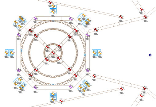
ToolsThe hoist tools in the Vectorworks Spotlight program assist with the design and documentation of overhead stage rigging equipment. Hoists are placed in a drawing that normally already contains lighting, staging, audio equipment, and the loads that will hang from the hoists. In addition, hoists can be used in conjunction with Braceworks rigging drawings and calculations. A suite of tools and commands assists you with creating all the diagrams and paperwork needed for rigging work.
~~~~~~~~~~~~~~~~~~~~~~~~~
 Placing Hoist
Origins
Placing Hoist
OriginsMode |
Tool |
Tool set |
|---|---|---|
Modes for The Symbol Insertion Tool |
Hoist Origin
|
Rigging |
The hoist origin serves as a reference point for associated hoists. Several hoist origins can be placed in the drawing, and different hoists can refer to different hoist origins. The coordinates displayed for each hoist are based on its position relative to the assigned hoist origin.
To place a hoist origin:
1 Click the tool and mode.
2 Click in the drawing to place the hoist origin.
The first time you use the tool in a file, a properties dialog box opens. Set the default properties. The properties can be edited from the Object Info palette.
► Clique para exibir/ocultar parâmetros.

~~~~~~~~~~~~~~~~~~~~~~~~~
 Placing Hoists
Tool |
Tool set |
|---|---|
Hoist
|
Rigging |
The Hoist tool places the hoists in the drawing.
To place a hoist in the drawing:
1 Click the tool.
2 Click in the drawing to place the hoist.
The first time you use the tool in a file, a properties dialog box opens. Set the available default properties (some properties are set automatically based on the selected symbol). The properties can be edited from the Object Info palette.
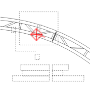
Using Auto Connect technology from Braceworks, when placing the hoist preview over an existing valid structural object such as a truss, the hoist insertion point is highlighted to indicate that when it is placed there, the hoist is automatically connected to the structural system.
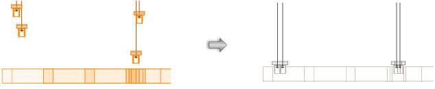
The hoist’s graphical representation in Top/Plan view depends on whether the hoist motor is up or down, as well as its load rating and its manufacturer or function. Hoist symbols, which can be customized, are available in the Vectorworks Libraries\Defaults folder; a selected hoist symbol is automatically imported into the current file and displays in the Resource Manager; see Resource Manager. The display of the hoist number, dimensions, and labels can be adjusted from the Object Info palette, and with the Set Hoist Number and Dimension Display command, or by making the associated number or label class invisible.

Number the hoists so that they have unique IDs in reports and calculations (Braceworks required).
After placement, hoists can be selected based on Object Info palette categories like the function, location, and type with the Select Hoists command.
► Clique para exibir/ocultar parâmetros.
~~~~~~~~~~~~~~~~~~~~~~~~~
 Hoist Display Options
The hoist display labels can be tailored for customized data display.

Transfer label positions between hoists or hoist origins with the Eyedropper tool.
Hoists used with Braceworks receive color-coded label fills to indicate their calculation status.
Hoists can display with a custom selection of labeled data fields. The settings can apply to one or more selected hoists, to all hoists, and can be set as the default for new hoists.
To specify the display of hoist data:
1 From the Object Info palette of a selected hoist, click Set Hoist Data Display.The Set Hoist Data Display dialog box opens.
2 Select which data fields should display with the hoist, and set the appearance.
► Clique para exibir/ocultar parâmetros.
Command |
Path |
|---|---|
Set Hoist Number and Dimension Display |
Spotlight > Hoists |
Hoists can display with the customized hoist number and dimension display option. The settings apply to all hoists in the file, although some of the options, such as the display of X and Y labels, can be overridden for individual hoists from the Object Info palette.
To specify the display of hoist numbers and dimensions:
Select the command. The Set Hoist Number and Dimension Display dialog box opens. Specify how the hoist number label and dimensions should display.
► Clique para exibir/ocultar parâmetros.
The settings apply to all hoists in the drawing.
The dimension rotation automatically updates when the associated hoist origin is moved.
~~~~~~~~~~~~~~~~~~~~~~~~~
 Selecting Hoist Objects
Commands allow hoist and hoist origin objects to be quickly selected so that a variety of operations can be performed on the selection.
Number hoists with the Spotlight Numbering command; see Numbering Light Plot Objects.
~~~~~~~~~~~~~~~~~~~~~~~~~
 Selecting
Hoists or Hoist Origin Objects
Selecting
Hoists or Hoist Origin ObjectsCommand |
Path |
|---|---|
Select Hoists |
Spotlight > Hoists |
All hoists or hoist origin objects can be selected, or specific hoists can be selected.
To quickly select hoist or hoist origin objects:
Select the command.
The Select Hoists dialog box opens; set the selection criteria.
► Clique para exibir/ocultar parâmetros.
~~~~~~~~~~~~~~~~~~~~~~~~~
 Selecting
and Assigning Hoist Origins
Selecting
and Assigning Hoist OriginsCommand |
Path |
|---|---|
Assign Origin to Selected Hoists |
Spotlight > Hoists |
Paired hoists and hoist origins can be quickly selected. Right-click on the hoist and select Select Hoist’s Origin from the context menu, or right-click on the hoist origin and select Select Origin’s Hoist from the context menu.
In addition, selected hoists can be quickly set to a specific hoist origin object, or a new hoist origin can be created.
To assign hoists to a hoist origin object:
1 Select the hoists to be assigned.
2 Select the command.
3 Click on the existing hoist origin, or click in a blank area of the drawing to create a hoist origin for the selected hoists.
Alternatively, right-click on the hoist origin and select Assign to Selected Hoists from the context menu.
The selected hoists are assigned to the hoist origin. The Measured From parameter in the hoist Object Info palette updates to reflect the new hoist origin.
~~~~~~~~~~~~~~~~~~~~~~~~~
 Setting Hoist Heights
Several commands assist with setting the height of the hoist hooks in relation to loads and associated items or to each other. While these can be set individually from the Object Info palette, using these commands is much easier when editing more than one hoist at once.
~~~~~~~~~~~~~~~~~~~~~~~~~
 Setting the
Low Hook Based on the Load Trim
Setting the
Low Hook Based on the Load TrimCommand |
Path |
|---|---|
Specify Selected Load Trims |
Spotlight > Hoists |
This command is useful when setting the height of hoists to their associated truss or hanging position loads. By specifying the bottom height of the load, the hoists, and optionally the load, automatically adjust to the correct height.
To set the low hook height of hoists assigned to a load:
1 Switch to a side 3D view, like Left, Right, or Front, that shows the hoists and the load.
2 Select the hoists to adjust. To also adjust the height at the bottom of the load, select the load as well.
3 Select the command. The Enter Value dialog box opens.
4 Specify the elevation of the bottom of the load.
The hoists are set to the adjusted Low Hook Height, while accounting for the Low Hook to Load Trim offset. If the load was also selected, its Z height (elevation) is also set.
~~~~~~~~~~~~~~~~~~~~~~~~~
 Setting the
Low Hook Based on a Selected Load
Setting the
Low Hook Based on a Selected LoadCommand |
Path |
|---|---|
Set Selected Load Trims |
Spotlight > Hoists |
When it is not obvious or easy to determine the elevation of a load, the height of selected hoists can still be set to an object in the drawing (usually a truss or hanging position). The low hook height of several hoists can also be set to that of another hoist, quickly setting all the hoists to the same height without needing to know the specific height.
To set the low hook height of hoists to an object or other hoist:
1 Switch to a side 3D view, like Left, Right, or Front, that shows the hoists and the load.
2 Select the hoists to adjust. To also adjust the height at the bottom of any other objects at the same time, select them as well.
3 Select the command.
4 Click on the reference object, such as a load or another hoist.
5 The hoists are set to the adjusted Low Hook Height. If other objects were selected, the Z height (elevation) of their bottom height is also set.

~~~~~~~~~~~~~~~~~~~~~~~~~
 Setting the
High Hook Height
Setting the
High Hook HeightCommand |
Path |
|---|---|
Set Selected High Hook Height |
Spotlight > Hoists |
The high hook height of selected hoists can be automatically set to the height of a clicked point. Only selected hoist objects are adjusted by this command (no other drawing objects can be selected).
To set the high hook height of selected hoists:
1 Switch to a side 3D view, like Left, Right, or Front, that shows the hoists.
2 Select the hoists to adjust.
3 Select the command.
4 Click on the reference object, such as the bottom of a support structure, or another hoist. The selected object is highlighted.
The hoists are set to the adjusted High Hook Height.

~~~~~~~~~~~~~~~~~~~~~~~~~
 Setting
Individual High Hook Height
Setting
Individual High Hook HeightCommand |
Path |
|---|---|
Set Individual High Hook Heights |
Spotlight > Hoists |
The high hook height of hoists can be automatically set to a clicked point, one by one. The hoists do not have to be set to the same high hook height. Only hoist objects are adjusted by this command (no other drawing objects can be selected).
To set the individual high hook heights of hoists:
1 Switch to a side 3D view, like Left, Right, or Front, that shows the hoists.
2 Select the command.
3 Click on the first hoist, which is highlighted. Click on its trim point, which is usually a support structure, but can be another hoist.
4 Click on the next truss and its trim point.
5 When finished assigning high hook heights, click in a blank area of the drawing.
The hoists are set to the adjusted High Hook Height.

~~~~~~~~~~~~~~~~~~~~~~~~~
 Hoist Data
After placement, hoist data can be displayed in worksheets and keys, and data can be exported and imported.
~~~~~~~~~~~~~~~~~~~~~~~~~
 Creating a
Hoist Worksheet
Creating a
Hoist WorksheetCommand |
Path |
|---|---|
Create Hoist Worksheet |
Spotlight > Reports |
The Create Hoist Worksheet command creates an editable worksheet with database rows. For more information about worksheets, see Worksheets.
To create a hoist worksheet:
Select the command. The Make Hoist Worksheet dialog box opens. Select the hoist data to include in the worksheet.
► Clique para exibir/ocultar parâmetros.
The worksheet rows are sorted by the unique hoist number. In addition to the selected fields, the hoist’s layer, name, and symbol used information is included. At the bottom of the worksheet, a hoist inventory sorts the hoists by hoist type, manufacturer, function, and total numbers.
Because the hoist worksheet consists of database rows, edits to the worksheet are applied to the objects in the drawing.
Once the worksheet has been generated, reflect any drawing changes by selecting the Create Hoist Worksheet command again.
~~~~~~~~~~~~~~~~~~~~~~~~~
 Creating
a Hoist Key
Creating
a Hoist KeyCommand |
Path |
|---|---|
Create Hoist Symbol Key |
Spotlight > Reports |
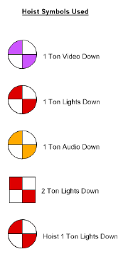
The Create Hoist Symbol Key command generates a key showing the various hoist symbols used in the file.
To create a hoist key:
1 Select the command.
2 Click to place the key in the drawing.
~~~~~~~~~~~~~~~~~~~~~~~~~
 Importing and Exporting Hoist
Data
Importing and Exporting Hoist
DataHoist data can be exported for use in common spreadsheet programs for further data analysis and paperwork processing, or for creating hoist label sheets. Hoist data can also be imported from a tab-delimited text file, updating the hoist objects. It may be convenient to assign control channels to hoists in an external software program, and import this information into the Vectorworks file.
Command |
Path |
|---|---|
Export Hoist Data |
File > Export |
To export hoist data:
1 Select the command.
The Export Hoist Data dialog box opens. Select whether to export to a tab-delimited (.txt) or comma-delimited (.csv) file.
2 Specify the export file name and destination.
All relevant hoist data is exported for each hoist in the file.
Command |
Path |
|---|---|
Import Hoist Data |
File > Import |
Hoists should already be present in the drawing. Hoists are updated based on the unique hoist number. All hoists that match by hoist number are updated at one time.
To import hoist data:
1 Select the command.
2 Select the tab-delimited file to import.
The hoists are updated with the new data, and then refreshed.
~~~~~~~~~~~~~~~~~~~~~~~~~
 Bridles
Creating bridles is a common practice for event riggers. Vectorworks Spotlight offers a suite of commands and tools for designing and analyzing bridles and their connected support structures. With a Braceworks license, you can perform load calculations to assess the structural stability of the rigging system. When the design is complete, bridle assembly diagrams and parts lists can be easily generated for the riggers on-site.
 Workflow:
Pre-rigging the Event
Workflow:
Pre-rigging the EventAt the start of a rigging project, create a “house file” for the venue that defines the available rigging points and their load limits. Once the “house” is modeled, insert the rigging structures and loads required by the event. Then insert the bridles needed to support the event rigging.
To pre-rig the event:
1 Create a house file for the venue. This model can be reused to pre-rig other events in the same space. Specify the basics of the drawing, such as establishing the layer scale, creating layers, setting up Spotlight preferences, and so on. Model the venue space.
Create layers to suit your rigging needs. To pre-rig a trade show, for example, place each booth on a separate design layer. The bridle paperwork can be organized by layer to create a separate parts list for each booth.
2 Use the Insert House Rigging Point tool, the Insert House Rigging Point at Selection command, and the Structural Member tool to define the available rigging points where bridles can attach. If the existing points are inadequate, use the Insert Mother Grid tool to place a truss system in the drawing.
3 Define the load limits for the house rigging points by setting their Allowable Force values.
4 When the house file is complete, model the event rigging. Insert trusses and lighting pipe. Add drops, such as hoists and dead hangs, to suspend the rigging system. Add load objects such as lights, speakers, video screens, and so on, or insert a point load or distributed load with the Insert Load tool.
5 Manage the bridle inventory. Select Manage Bridle Parts to specify the available parts and their properties.
6 Select Bridle Preferences to define the default properties of bridle objects.
7 Use the Insert Bridle tool to insert bridles in the drawing.
8 From the Bridle Configuration dialog box, adjust how specific bridles are built from the available parts.
9 Calculate the forces applied to the rigging system (Braceworks required). Make changes to the system as needed.
It is recommended that you calculate forces throughout the design process (Braceworks required), to adjust the design for viable rigging.
10 Create the bridle paperwork.
• Select the Bridle Report command to create a bridle parts worksheet. The data can be sorted to assist with organization and assembly.
• Select Create Bridle Assembly Diagrams to generate diagrams, and optional parts lists, for the bridles.
~~~~~~~~~~~~~~~~~~~~~~~~~
 Inserting
House Rigging Points
Inserting
House Rigging Points
The Insert House Rigging Point tool is in the Rigging tool set.
House rigging points are defined early in the design process. They represent the existing points in a venue where mother grids and bridles can be inserted. Use the Insert House Rigging Point tool to place house rigging points in the drawing.
Bridles can also be inserted on and snapped to structural members, if the option to Use Structural Member as House Rigging Point is enabled from the Bridle Preferences.

To insert a house rigging point:
1 Click the tool, and then click Preferences to set the default properties for house rigging points.
2 Click Symbol on the Tool bar. From the Resource Selector, double-click a resource to activate it.
Alternatively, from the Resource Manager, either double-click the house rigging point symbol to insert or right-click on the house rigging point symbol and select Make Active from the context menu.
3 Enter the Trim Height of the house rigging point on the Tool bar.
4 Click to place the object in the drawing.
You can insert multiple house rigging points at once. To insert a house rigging point on each selected object, see Inserting House Rigging Points on Selected Objects. To duplicate house rigging points, use the Duplicate Array and Duplicate Along Path commands; see Duplicate Array and Duplicating Objects Along a Path.
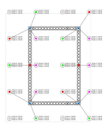
The house rigging point is inserted in the drawing, with a display of the forces.
Click and drag the label control point to move the displayed forces. Select Text > Size to resize the text if needed.
5 Specify the Allowable Force X/Y/Z values on the Object Info palette to set the load limits of the rigging point.

The house rigging point properties can be edited from the Object Info palette.
► Clique para exibir/ocultar parâmetros.
For structural engineering purposes, you can define the element coordinate system of a house rigging point. For example, rotate the Force X/Y/Z values for alignment to a structural member.
To define the element coordinate system:
1 Select one or more house rigging points.
2 Click Define ECS on the Object Info palette.
3 Click in the drawing to define the force orientation. For example, click on the centerline of a beam to define the forces in the beam direction.
Alternatively, use the Rotate tool to change the force orientation, or set the Rotation from the Object Info palette.
The forces are oriented in the specified direction. To calculate the forces, see Performing Calculations (Braceworks required). If the forces were calculated previously, the calculation results automatically adjust to the new orientation.

~~~~~~~~~~~~~~~~~~~~~~~~~
 Inserting
House Rigging Points on Selected
Objects
Inserting
House Rigging Points on Selected
ObjectsCommand |
Path |
|---|---|
Insert House Rigging Point at Selection |
Spotlight > Rigging |
Use the Insert House Rigging Point at Selection command to insert a house rigging point on each selected object.
To insert house rigging points on selected objects:
1 Select the command.
The Select Symbol dialog box opens.
2 Select a house rigging point symbol from the Resource Selector.
A house rigging point is inserted on each selected object.
~~~~~~~~~~~~~~~~~~~~~~~~~
 Inserting Mother Grids
The Insert Mother Grid tool is in the Rigging tool set.
When a venue’s rigging points are insufficient, a mother grid can be added. Mother grids can support the horizontal forces applied by bridles. Each mother grid consists of one truss and three hoist objects. Use the Insert Mother Grid tool to place a mother grid on house rigging points or structural members (see Creating Structural Members).
The following modes are available:

Mode |
Description |
|---|---|
Auto Insertion |
Inserts a mother grid using Auto Connect technology to highlight valid attachment points |
Click Insertion |
Inserts a mother grid with three clicks to identify the start point, end point, and connection point of the truss system |
Symbol |
Select the truss symbol to insert |
Trim Height |
When Click Insertion is selected, enter the trim height of the mother grid in 2D views |
Preferences |
Opens the Insert Drop dialog box, to select the hoist or dead hang symbol to use in the mother grid |

~~~~~~~~~~~~~~~~~~~~~~~~~
 Inserting
Mother Grids Automatically
Inserting
Mother Grids AutomaticallyMode |
Tool |
Tool set |
|---|---|---|
Auto Insertion |
Insert Mother Grid
|
Rigging |
To insert a mother grid automatically:
1 Click the tool and mode.
2 Click Symbol on the Tool bar. From the Resource Selector, double-click a resource to activate it.
3 Move the mouse to hover over the rigging object that the mother grid will support.
Using Auto Connect technology, a preview of the truss system is dynamically displayed on possible connection points.
4 Click on the rigging object at the desired connection point. The mother grid is inserted in the drawing.

The properties of the hoist and truss objects can be edited from the Object Info palette.
~~~~~~~~~~~~~~~~~~~~~~~~~
 Inserting
Mother Grids Manually
Inserting
Mother Grids ManuallyMode |
Tool |
Tool set |
|---|---|---|
Click Insertion |
Insert Mother Grid
|
Rigging |
To insert a mother grid manually:
1 Click the tool and mode.
2 Click Symbol on the Tool bar. From the Resource Selector, double-click a resource to activate it.
3 Enter the Trim Height of the mother grid on the Tool bar.
4 Click once to set the start point of the truss, and click again to set the end point.
5 Click to define the connection point on the rigging object that the mother grid will support.
The mother grid is inserted in the drawing.

The properties of the hoist and truss objects can be edited from the Object Info palette.
~~~~~~~~~~~~~~~~~~~~~~~~~
 Managing Bridle Parts
Command |
Path |
|---|---|
Manage Bridle Parts |
Spotlight > Rigging |
The Manage Bridle Parts dialog box provides information about the bridle inventory. Select which parts can be used in the drawing, and edit their properties if needed.
To view and manage the bridle inventory:
1 Select the command.
The Manage Bridle Parts dialog box opens.
► Clique para exibir/ocultar parâmetros.
2 Advanced users can add or remove items from the bridle parts list. Edit the symbols in the Stock Bridle Material folder in the [User]\Libraries\Defaults folder. Click Update in the Manage Bridle Parts dialog box to refresh the bridle parts list.
3 To edit the properties of an item in the bridle parts list, double-click on the row item. The Edit Bridle Part dialog box opens. The available properties depend on the bridle part. Edit the properties as needed, and click OK.
Be cautious when editing the Length of a bridle part that is currently used in the drawing; existing bridles may become invalid.
4 Click OK to update the drawing with any changes to the bridle parts list.
~~~~~~~~~~~~~~~~~~~~~~~~~
 Bridle Preferences
Command |
Path |
|---|---|
Bridle Preferences |
Spotlight > Rigging |
Set the bridle preferences prior to inserting bridles in the drawing. Applying one of the Default Bridle Parameters ensures that all subsequently placed bridles have at least one dimension in common, to facilitate planning and assembly. Specify the default dimensions and parts. Optionally, enable the use of structural members as house rigging points. The settings apply to the current file.
To set the bridle preferences:
1 Select the command.
The Bridle Preferences dialog box opens.
► Clique para exibir/ocultar parâmetros.
2 Specify the default settings for bridle objects.
~~~~~~~~~~~~~~~~~~~~~~~~~
 Inserting Bridles
The Insert Bridle tool is in the Rigging tool set.
The Insert Bridle tool places a bridle object in the drawing. Bridle legs can be inserted on house rigging points and mother grids, and on structural members if this option is enabled when setting the Bridle Preferences. Before a bridle is inserted, make sure the necessary rigging points are present in the drawing.
The following modes are available:

Mode |
Description |
|---|---|
Auto Insertion Mode |
Inserts the bridle with one click to define the connection point on the object that the bridle will support; the legs are automatically inserted on the closest rigging points |
Click Insertion Mode |
Inserts the bridle with multiple clicks, to define the connection point on the object that the bridle will support, and to define each leg insertion point |
Deadhang |
Inserts a deadhang, to suspend a load directly below a rigging point |
Two Leg Bridle |
Inserts a two leg bridle |
Reversed Two Leg Bridle |
Inserts a reversed two leg bridle, to connect multiple objects to a rigging point. To calculate the forces correctly with Braceworks, the objects must be on the same truss system. |
Three Leg Bridle |
Inserts a three leg bridle |
Four Leg Bridle |
Inserts a four leg bridle |
Stacked Bridle |
Inserts a stacked bridle, which is structurally determinate |
Trim Height |
When Click Insertion is selected, enter the trim height of the bridle in 2D views |
~~~~~~~~~~~~~~~~~~~~~~~~~
 Inserting
Bridles Automatically
Inserting
Bridles AutomaticallyMode |
Tool |
Tool set |
|---|---|---|
Auto Insertion |
Insert Bridle
|
Rigging |
To insert a bridle automatically:
1 Click the tool and insertion mode.
2 Click the bridle type mode.
The Auto Insertion mode is not available when inserting reversed two leg bridles.
3 Hover the mouse over the object that the bridle will support.
Using Auto Connect technology, the valid connection points are highlighted, and a preview of the bridle legs is dynamically displayed.
4 Click on the rigging object to insert the bridle as previewed.
The bridle is inserted in the drawing according to the settings in the Bridle Preferences dialog box.

The Bridle Properties can be edited from the Object Info palette.
~~~~~~~~~~~~~~~~~~~~~~~~~
 Inserting
Bridles Manually
Inserting
Bridles ManuallyMode |
Tool |
Tool set |
|---|---|---|
Click Insertion |
Insert Bridle
|
Rigging |
The Click Insertion mode uses multiple clicks to insert a bridle object. For most bridle types, the first click defines the bridle’s connection point on the object it will support, and subsequent clicks define the leg insertion points. Reversed two leg bridles are inserted differently.
To insert a bridle manually:
1 Click the tool and insertion mode.
2 Click the bridle type mode.
3 Enter the Trim Height of the bridle on the Tool bar.
4 If inserting a reversed two leg bridle, do the following. If inserting any other bridle type, follow steps 5 and 6.
• Click on the rigging object to set the insertion point for Leg 1, and click again to set the insertion point for Leg 2. The available insertion points are highlighted as the cursor moves over them.
• Click on the rigging point where the bridle will attach. Valid insertion points are highlighted as the cursor moves over them.
5 Hover the mouse over the object that the bridle will support, and click to set the connection point. Valid connection points are highlighted as the cursor moves over them.
6 Insert the bridle legs. For each leg, click on the rigging point where the leg will attach. The available insertion points are highlighted as the cursor moves over them.
The bridle object is inserted in the drawing.

The Bridle Properties can be edited from the Object Info palette.
~~~~~~~~~~~~~~~~~~~~~~~~~
 Bridle Properties
Bridle properties can be viewed and edited from the Object Info palette. The available leg length parameters depend on the bridle type.
► Clique para exibir/ocultar parâmetros.
~~~~~~~~~~~~~~~~~~~~~~~~~
 Adjusting
the Bridle Configuration
Adjusting
the Bridle ConfigurationOnce a bridle is inserted in the drawing, you can adjust how each leg is configured from the available parts. The list of available parts can be edited from the Manage Bridle Parts dialog box. Add and remove parts from the Basket Parts and Leg Parts lists to achieve the required dimensions, displayed in the Bridle Geometry diagram.
To set the bridle configuration:
1 Select the bridle, and click Bridle Configuration from the Object Info palette.
The Bridle Configuration dialog box opens.
► Clique para exibir/ocultar parâmetros.
2 Select the bridle leg to configure from the Define list.
3 In the Available Parts list, click “+” (Windows) or triangle (Mac) next to each part type to view the available items.
4 Click Manage Bridle Parts to add, remove, or edit items in the Available Parts list (see Managing Bridle Parts).
5 Select Summarize Parts List or List All Parts, to determine how the materials are displayed in the Basket Parts and Leg Parts lists.
6 Specify which basket parts are used to make the bridle leg.
• To add a part, select it from the Available Parts list and click Add directly below the Basket Parts list.
Alternatively, select an item from the Available Parts list and drag it to the Basket Parts list. If List All Parts is selected, you can drag the item to a desired position in the Basket Parts list; otherwise, the item is added to the end of the list.
• To remove a part, select it from the Basket Parts list and click Remove directly below the list.
The Parts Length value and the Bridle Geometry diagram update to reflect changes to the selected basket parts.
7 Repeat the previous step with the Leg Parts list to specify which leg parts are used.
8 To change the order of items in the Basket Parts or Leg Parts list, select List All Parts, then select an item in the list and drag it to the desired position.
9 Set the Basket Dimensions. From the Preset list, select the object that the basket attaches to, or select <No Basket>. If <Custom Basket> is selected, enter the dimensions.
10 Continue configuring each leg as needed. Click OK to update the bridle in the drawing.
Select the Undo command to restore the previous bridle configuration.
~~~~~~~~~~~~~~~~~~~~~~~~~
 Creating a
Bridle Assembly Diagram
Creating a
Bridle Assembly DiagramCommand |
Path |
|---|---|
Create Bridle Assembly Diagrams |
Spotlight > Rigging |
Create simple assembly diagrams for selected bridles in the drawing. Each diagram includes a schematic drawing with labeled parts and an optional parts list. The diagrams can be placed on a sheet layer or design layer, and arranged in one or more columns.
To create a bridle assembly diagram:
1 Select one or more bridle objects, and select the command.
The Create Bridle Assembly Diagram dialog box opens.
► Clique para exibir/ocultar parâmetros.
2 Set the parameters for the bridle assembly diagram.
A diagram is created for each selected bridle. If multiple diagrams are created, they are arranged in the specified Number of columns.
To print one diagram per sheet, place the bridle assembly diagrams in one column on a sheet layer. Set the diagram size to match the Printable Area dimensions specified in Page Setup. From the Page Setup dialog box, set the Vertical page count to match the number of selected bridles.
3 Click and drag the bridle assembly diagram to reposition it. To reposition the parts list independent of the assembly drawing, click the control point at the bottom of the parts list, and click again at the desired location.
4 Use the Text menu commands to edit the font, size, and style of the text in the entire assembly diagram; see Formatando Textos.
The parameters can be edited from the Object Info palette.
► Clique para exibir/ocultar parâmetros.

~~~~~~~~~~~~~~~~~~~~~~~~~
 Creating a
Bridle Report
Creating a
Bridle ReportCommand |
Path |
|---|---|
Create Bridle Report |
Spotlight > Reports |
The Create Bridle Report command adds a bridle parts worksheet to the drawing. Specify which bridles to include in the worksheet and, optionally, sort the data by layer or class. For more information about worksheets, see Worksheets.
To create a bridle report:
1 Select the command.
The Create Bridle Report dialog box opens.
► Clique para exibir/ocultar parâmetros.
2 Select the worksheet criteria.
A Bridle Parts List worksheet is inserted in the drawing.
~~~~~~~~~~~~~~~~~~~~~~~~~


