PlantasPlantas
The Plant tool is in the Site Planning tool set.
In the Vectorworks Landmark product, plant objects are inserted from a plant style and can be customized individually per instance. The Plant tool both defines and places plant objects.
• A plant style prescribes the 2D and 3D appearance, parameters, and botanical data for a specific type of plant. Use one of the many plant styles that come with Vectorworks, or create your own. The plant style is specified from the Plant Style dialog box with parameters appropriate for the plant type, or by loading botanical data from either plant catalogs or a plant database. When plant styles are defined, the parameters apply by default to all plants of that style inserted in the drawing.
• A plant object or plant instance refers to a specific plant that is inserted in a drawing with the Plant tool. The plant object is based on a plant style, but like many objects in Vectorworks, the parameters of individual plant instances can be changed by editing plant preferences to allow for realistic variation among individual plants based on the same plant style. Each individual plant object can be edited to customize its parameters, either before placement by Setting Object Properties or after placement for selected plant objects from the The Object Info Palette.
~~~~~~~~~~~~~~~~~~~~~~~~~
 Adding
Plants to the Design
Adding
Plants to the DesignTool |
Tool set |
|---|---|
Plant
|
Site Planning |
Every plant object in the drawing is based on a plant style selected from the Resource Selector. Plant parameters are set by the style, but if necessary, the default settings for certain parameters can be changed in the Plant Preferences or Advanced Plant Preferences dialog box before placement. Selected plants can be edited from the Object Info palette after placement.
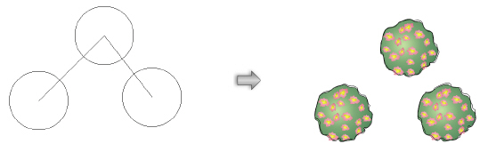
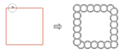
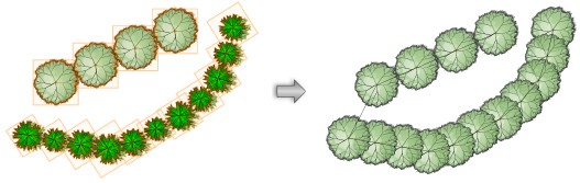
In addition to the appearance and parameters defined for plants, the Plant tool can place plants in several configurations, from single plants to arrays of plants. When setting parameters after placement, an array of plants is considered to be a single “plant” in the Object Info palette. Plants can also created by drawing a polyline and then selecting the Create Objects from Shapes command (see Creating Objects from Shapes).
See Conceito: Visão Geral sobre Plantas for a discussion of the relationship between plant styles and the preferences for an individual plant instance.

Mode |
Description |
|---|---|
Insertion |
Inserts a plant according to the selected placement mode |
Pickup |
Sets the default plant preferences to match those of a selected existing plant |
Massing Creation |
Uses the current plant preferences to convert a polyline, polygon, rectangle, circle, or arc into a plant object |
Plant Style |
Opens the Resource Selector to select a plant style for placement; double-click a resource to activate it |
Single Plant Placement |
Places a single specified plant at each mouse click
|
Poly-Vertex Placement |
Places plants at each clicked polygon vertex
|
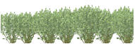
Poly-Edge Spaced |
Places plants along the drawn polygon at the Spacing distance specified in the style or preferences
|
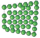
Rectangular Array |
Fills the drawn polygon with plants in a rectangular array at the Spacing distance specified in the style or preferences
|
Triangular Array |
Fills the drawn polygon with plants in a triangular array at the Spacing distance specified in the style or preferences
|
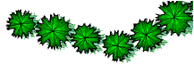
Hedge |
Enables hedge creation for the Poly-Edge Spaced, Rectangular Array, and Triangular Array placement modes. When toggled on, creates rows of hedges along the drawn polyline; the number of hedge rows is set in the Preferences.
|
Preferences |
Opens the Plant Preferences or Advanced Plant Preferences dialog box, for specifying the plant style and its parameters |
To place plants on the drawing:
1 Click the tool.
2 Click Plant Style on the Tool bar. From the Resource Selector, double-click a resource to activate it.
Alternatively, click Preferences to open the Plant Preferences dialog box. Click Plant Style to open the Resource Selector, and double-click a plant style to activate it. Then specify any plant preferences that are different from the style, if needed.
The Plant tool retains these preferences until they are changed by selecting a different plant style, editing the default plant preferences, or until Pickup mode is selected, which changes the default preferences to those of a selected existing plant.
The Plant Preferences dialog box opens automatically if you click in the drawing area before selecting a Plant Style from the Tool bar. To open the Advanced Plant Preferences dialog box by default instead of Plant Preferences, see Advanced Plant Preferences: Options Pane.
Alternatively, double-click a plant symbol from the Resource Manager to activate the Plant tool, and then click in the drawing to place the selected plant.
3 Select the plant placement mode from the Tool bar.
4 In Insertion mode, depending on the placement method selected, either click in the drawing to place a single plant, click to set vertices, or draw a polygon. As the Plant tool is clicked in the drawing, a preview of the plant spread is displayed to help with plant placement.
In Massing Creation mode, valid objects are highlighted as the cursor moves over them. Click on a valid object to place the plant. According to the placement settings, the plant follows the path of, or fills, the object.
By default, Vectorworks displays the basic Plant Preferences dialog box when first inserting a plant. The properties can be edited from the Object Info palette. See the Advanced Plant Preferences: Options Pane to display the Advanced Plant Preferences dialog box by default.
Changes made to the preferences do not affect the plant style.
► Clique para exibir/ocultar parâmetros.
By default, when Adding Plants to the Design, Vectorworks opens the basic Plant Preferences dialog box, where the plant style is selected, and basic preferences for a plant instance can be set. However, there are times when more detailed preferences are needed, including custom sizing, schedule information, and visualization details.
To access the Advanced Plant Settings dialog box, click Advanced Settings on the Plant Preferences dialog box or click Advanced Plant Settings on the Object Info palette. To change the software default to open the advanced dialog box when inserting a plant or clicking Preferences from the Tool bar, see Advanced Plant Preferences: Options Pane.
Throughout plant documentation, any reference to the Plant Preferences dialog box also includes an implied reference to the Advanced Plant Preferences dialog box. Any features that require use of the Advanced Plant Preferences dialog box specify it.
Changes made to the preferences do not affect the plant style.
► Clique para exibir/ocultar parâmetros.
The Plant Style pane is used to select the plant style for placement by the Plant tool. Clique para exibir/ocultar parâmetros.
Parameter |
Description |
|---|---|
Plant Style |
Displays the name of the current plant style |
Plant selector |
Opens the Resource Selector to select a plant style for placement; double-click a resource to activate it |
Latin/Common |
Displays the name of the plant style for the selected plant |
Duplicate |
Creates a duplicate plant based on the selected plant’s style |
The Size pane displays the default size settings from the plant style; see Plant Style: Insertion Options Pane.
► Clique para exibir/ocultar parâmetros.
The Schedule pane displays the default schedule settings from the plant style; see Plant Style: Schedule Pane. For each parameter, select Use Plant Style, or select Custom and enter a value.
The Visualization pane displays the plant massing and shadow visualization settings from the plant style; see Plant Style: Visualization Pane. For outline and massing, select Use Plant Style, or select the Custom outline and massing option. For the shadow in plan view, select the No Shadow, Use Plant Style, Use Document Preference Settings, or Custom shadow setting (for custom options, see Plant Shadow Settings).
Select plant display parameters; see Plant Preferences.
Set the display of the plant ID tags; see Plant Preferences. To create a custom plant tag, see Creating a Custom Plant Tag. After creation, the plant tag’s appearance can also be modified via the Object Info palette, tag class settings, and the control point locations on the drawing (see Plant Tag Appearance).
Select Show Advanced Plant Settings to automatically display the Advanced Plant Preferences dialog box instead of the Plant Preferences dialog box when placing and editing plants and when Preferences is clicked from the Tool bar. When this option is selected, Advanced Plant Settings is available on the Object Info palette.
~~~~~~~~~~~~~~~~~~~~~~~~~
 Creating
a Custom Plant Tag
Creating
a Custom Plant TagIn addition to providing several predefined plant tags, designers can create custom plant tags.
1 From the Tag section of the Plant Preferences dialog box, select Set Custom Tag from one of the Top/Center/Bottom fields.
The Set Custom Tag dialog box opens.The current plant tag’s settings populate the selections; if editing an existing tag through the Object Info palette, the selected tag’s data displays.
2 Select values from predefined plant record fields in the order they should be listed, and type the delimiter text to place between the fields. Select <New Line> to start the next tag item on a new line. Up to six different combinations of fields, delimiters, and new line separators can be used. Entering a custom tag in the Top field of the Plant Preferences dialog box will insert the custom tag above the reference line, a custom tag in the Center field will replace the reference line, entering a custom tag in the Bottom field will appear below the reference line.
The Tag Appearance field displays a static text preview of the custom tag. To preview a tag in its entirety, click-drag the bottom right corner of the dialog box to resize it.
When using images in the plant tag, edit each plant style and specify the image to use from the Plant Data pane (see Setting Plant Data Images.) Set the size of the image with the Image Size parameter in the Annotation pane.
3 Click OK.
4 Repeat for the other Top / Center / Bottom fields on the Plant Preferences dialog box, as appropriate, to complete creation of the custom tag.
~~~~~~~~~~~~~~~~~~~~~~~~~
 Creating Plant Styles
Command |
Workspace: Path |
|---|---|
Create Plant Style from Selection |
• Designer: AEC > Plants • Landmark: Landmark • Context menu |
Every plant instance inserted into a drawing is based on a plant style, which includes the 2D and 3D plant appearance and the parameters and botanical data for a specific type of plant. Botanical data for the plant styles come from either plant catalogs or the plant database. When the Vectorworks Landmark product is installed, a generic plant style library is included, and more plant content including 2D and 3D plant symbols is available for download. A selected plant is automatically imported into the current file and displays in the Resource Manager. Although Vectorworks libraries provide hundreds of plant styles ready for use in a drawing, you can also create your own custom plant styles, either by entering parameters and graphics or by loading and editing data from an existing plant style.
See Conceito: Visão Geral sobre Plantas for a discussion of the relationship between plant styles and the preferences for an individual plant instance.
To create a new plant style:
1 Open the Plant Style dialog box using one of the following methods:
• To create a new plant style based on an existing plant instance in the drawing, select the plant instance, and then select the command.
Alternatively, right-click on the plant instance and select the context command, or click Duplicate from the Plant Preferences dialog box (in the Advanced Plant Preferences dialog box, Duplicate is on the Plant Style pane).
• To create a new plant style based on 2D and 3D geometry in the drawing, select the geometry and then select the command.
Plant objects follow this special plant style procedure, rather than the general workflow for adding 2D components to other kinds of hybrid objects.
• To create a new plant style based on an existing plant style, from the Resource Manager, right-click on a plant style, and select Duplicate and then Edit Style from the context menu.
• Plant styles can also be created automatically by Creating Plant Styles from the Plant Catalog.
2 The Plant Style dialog box opens, displaying the parameters and graphics of the currently selected plant/style. Provide a name for the new style, and then specify the plant parameters on each pane to define the plant. As the parameters are defined, the preview dynamically displays the plant appearance.
Plant styles that have a corresponding plant catalog entry or plant database record automatically update the associated plant catalog/database to match any edits to the plant style, if Update the Plant catalog with Vectorworks Plant style changes or Update Plant Database with Vectorworks Plant style changes is selected (see Concept: Plant Style and Plant Data Integration). If there is no corresponding entry, an alert opens so that you can add the plant to the catalog or database if desired.
Plant resources can be exported from the Resource Manager or by selecting Export Plant from the plant context menu; see Exporting Resources.
If you want to set plant Z values to the site model surface, the plant styles and site model must be in the same file (they cannot be referenced).
Each pane of the plant style dialog box is described in the following sections.
• Plant Style: General Parameters
• Plant Style: Visualization Pane
• Plant Style: Insertion Options Pane
• Plant Style: Plant Data Pane
~~~~~~~~~~~~~~~~~~~~~~~~~
 Plant
Style: General Parameters
Plant
Style: General ParametersEvery pane of the plant style displays the Plant Style Name and dynamic previews.
► Clique para exibir/ocultar parâmetros.
~~~~~~~~~~~~~~~~~~~~~~~~~
 Plant
Style: Schedule Pane
Plant
Style: Schedule Pane Click the Schedule pane to specify default plant values for display and reporting; values and settings entered on this pane become the default for the plant style.
► Clique para exibir/ocultar parâmetros.
~~~~~~~~~~~~~~~~~~~~~~~~~
 Plant Style: Visualization
Pane
Plant Style: Visualization
PaneClick the Visualization pane to specify the plant appearance.
A document preference makes it easy to give plans a uniform appearance by applying a document-wide shadow style to all plants and massing models in a drawing (see Document Preferences: Plan Shadows Tab). Even when a document preference is set, plant styles can be edited on the Visualization pane to customize the drawing’s appearance. The outline, massing, and shadow parameters can be toggled on or off for all plants in a document by selecting View > Show > Show or Hide Plant Details.
The massing, outline, and shadow effects display in Top/Plan view only; plant shadows do not display in worksheet images.
Values and settings entered on this pane become the default for the plant style. Certain default values can be changed for individual plants after placement.
► Clique para exibir/ocultar parâmetros.
When generating plant geometry from another symbol, the 3D representation may not be available, or not suitable for the new plant. 3D geometry can be automatically generated, creating a suitable representation of the plant style in 3D views.
On the Plant Style: Visualization Pane, click Generate. The Generate 3D Plant Geometry dialog box opens.
► Clique para exibir/ocultar parâmetros.
~~~~~~~~~~~~~~~~~~~~~~~~~
 Plant
Style: Insertion Options Pane
Plant
Style: Insertion Options PaneSpecify the default insertion options for the plant style on the Insertion Options pane.
If plant data were obtained from the plant database, the plant database values are displayed. Values and settings entered on this pane become the default for the plant style.
► Clique para exibir/ocultar parâmetros.
~~~~~~~~~~~~~~~~~~~~~~~~~
 Plant
Style: Plant Data Pane
Plant
Style: Plant Data PaneClick the Plant Data pane to view the additional plant information.
The plant data parameters are listed; each one can be clicked and its Value displays below the list. Click Edit to change the value.
As described in Concept: Plant Style and Plant Data Integration, if either Update the Plant catalog with Vectorworks Plant style changes or Update the Plant Database with Vectorworks Plant style changes is selected in the Choose Plant Data Source dialog box, the associated plant catalog (or plant database) automatically updates with any changes made on the Plant Data pane.
If you are using a plant database file from a version of Vectorworks prior to 2018, the synchronization of images between the plant style and the plant database cannot occur even when using the Migration Manager during the version update, because the older plant database file does not include the new functionality. To fix this issue, export the records in the plant database with the File > Export Records plant database command. Then import the records back into the plant database with the File > Import Records plant database command.
Up to four plant images can be selected from the Data pane. The images can be synchronized with the images in the plant catalog or plant database; see Accessing the Plant Catalogs or Editing Plant Records. The fourth option, Custom Image, is not populated by default in the plant database, so it is useful for including an additional graphic in the plant style.
Other image sources, besides those from the plant catalog or database, can be specified from the Plant Data pane. If not using plant images from the plant style or the plant catalog/database, prepare image files or create/locate a suitable image resource.
To set the plant data image source:
1 In the Plant Style: Plant Data pane, scroll to the Image Plant Form, Image Detail, Image Misc, and Custom Image parameters.
2 Click on each one to set its image source. Set Image becomes available; click to specify the image for tag display.
The Set Plant Data Image dialog box opens. Specify the location of the plant image.
► Clique para exibir/ocultar parâmetros.
When an image source has been specified, <image> displays in the Value column of the Plant Data pane. The plant images are synchronized with the plant catalog or database. For this reason, the selection may change to Plant Image regardless of the original selection. For example, if you import an external file for the Image Detail, the plant catalog or database is updated with this image for the Detail Image. In the Set Plant Data Image dialog box, the setting switches to Plant Image since the image now originates from the catalog or database.
To prevent image and plant data synchronization between the associated plant catalog/database and the plant style, deselect either Update the Plant catalog with Vectorworks Plant style changes or Update the Plant Database with Vectorworks Plant style changes (see Selecting the Plant Data Source).
3 Display images in the drawing within plant tags by Creating a Custom Plant Tag, and add them to worksheets by Inserting Images in Worksheet Cells.
|
Click here for a video tip about this topic (internet access required). |
~~~~~~~~~~~~~~~~~~~~~~~~~
 Plant
Shadow Settings
Plant
Shadow SettingsTo create custom plant shadow settings for a plant style or a plant instance:
Click Settings from the Visualization pane of either the Plant Style dialog box or the Advanced Plant Preferences dialog box, depending on whether the custom settings are part of a plant style or for individual plant instances. The Plant Shadow Settings dialog box opens. Set the shadow settings.
► Clique para exibir/ocultar parâmetros.
~~~~~~~~~~~~~~~~~~~~~~~~~
 Editing Plant Styles
To add data to or edit and existing plant style, do one of the following:
• Right-click on a plant instance (in the drawing); select Edit from the context menu, and then click Style.
• From the Resource Manager, right-click on the plant style, and select Edit Style from the context menu.
• From the Plant Preferences dialog box, click Edit Plant Style.
The Plant Style dialog box opens. Set the plant style parameters and graphics as described in Creating Plant Styles.
 Deleting
Plant Styles
Deleting
Plant StylesWhen a plant style resource is deleted, all instances of the style in the current document can be deleted completely, replaced with loci to preserve the plant locations, or replaced with a different plant style.
To delete a plant style resource:
1 From the Resource Manager, right-click on the resource, and select Delete from the context menu. Alternatively, select the resource and press the Delete key.
2 If there are any instances of the plant style currently in the drawing, the Delete Plant dialog box opens.
► Clique para exibir/ocultar parâmetros.
The plant style resource is deleted and each plant instance is either deleted or replaced with a locus or the selected plant style.
 Plant ID Codes
The following table lists commonly used plant ID code categories.
Plant ID Code |
Meaning |
|---|---|
A-# |
Annual # |
CTD |
Conifer Tree Display |
CTG |
Conifer Tree Generic |
ETD |
Evergreen Tree Display |
ETG |
Evergreen Tree Generic |
G-# |
Grasses # |
OT-M |
Ornamental Tree Massed |
OTD |
Ornamental Tree Display |
OTF |
Ornamental Tree Flowering |
OTG |
Ornamental Tree Generic |
OTM |
Ornamental Tree Multi-Stem |
OTP |
Ornamental Tree Patio |
P-1–P-9 |
Perennials |
P1–P4 |
Palms |
SD-# |
Shrub Display # |
SD# |
Shrub Deciduous # |
SDM |
Shrub Display Massed |
SG# |
Shrub Evergreen # |
SG |
Shrub Generic |
SN# |
Shrub Needle # |
STG |
Shade Tree Generic |
STL |
Shade Tree Large |
STM |
Shade Tree Massed |
STP |
Shade Tree Patio |
STS |
Shade Tree Street |
 Editing
Plant Instances
Editing
Plant InstancesAs plants are placed, they take on the properties of the associated plant style and/or the properties in the Plant Preferences dialog box.
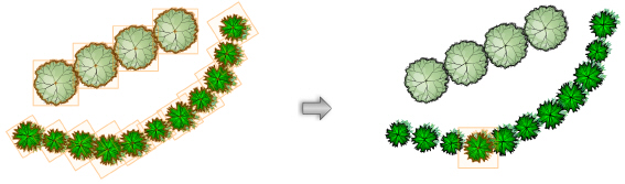
For multi-plant placement options, edit the polygon defining the plant with the Reshape tool if necessary; the plant placement automatically adjusts to fit the new shape.
Triangular and rectangular plant arrays include a special plant alignment control point, which indicates the center of a representative plant in the array. If moved, the array shifts to reposition the array about the new plant center.

Plant object parameters that are not defined by the plant style can be edited from the Object Info palette and from the Advanced Plant Preferences dialog box when it is accessed from the Object Info palette. Changes made for the selected plants apply only to those plant instances; changes are not reflected in the plant style or preferences. Plant parameters are described in Plant Preferences and Advanced Plant Preferences. Only the parameters that are different are described here.
► Clique para exibir/ocultar parâmetros.
See Conceito: Visão Geral sobre Plantas for a discussion of the relationship between plant styles and the preferences for an individual plant instance.
~~~~~~~~~~~~~~~~~~~~~~~~~
 Plant
Tag Appearance
Plant
Tag AppearancePlant tag appearance and placement is flexible, and can be adjusted in several ways, including through the plant preferences, Object Info palette, tag class settings, and the control point locations on the drawing.
• Individual plant tags can be changed for selected plants by adjusting the plant tag parameters from the Object Info palette. For example, selected plants in one area of a planting plan look more uniform when they all use the same tag approach and tag shoulder angle.
• The plant tag class controls the appearance of the leader/shoulder lines, as well as the marker style.
• Plant images can be added to a custom plant tag. The Image Size parameter, from the Annotation pane of the plant preferences, controls the size of the images.
• To move the plant tags of several selected plants at once, click the Unrestricted Interactive Scaling mode of the Selection tool.
• To align plant tags for improved readability, use the Align/Distribute Leader Lines command (see Aligning and Distributing Leader Lines).
• If an individual tag needs to be repositioned, plant tags also have several control points for adjusting the tag text and leader line and shoulder position and angle. Centered tags have X and Y offset parameters in the Object Info palette for positioning the tag.

~~~~~~~~~~~~~~~~~~~~~~~~~
 Editing
Plant Attributes
Editing
Plant AttributesPlants are hybrid symbols, containing a 2D symbol, and optionally, a 3D symbol. As plant styles are created, the plant symbol is automatically imported into the current file and displays in the Resource Manager. Plants are “red” plug-in object symbols (see Conceito: Vectorworks Símbolos for information on symbol types). The 2D and 3D plant graphics are scaled by the plant style height and spread parameters.
Because plants are red symbols, plant attributes cannot be directly set or modified from the Attributes palette. Instead, edit the plant symbol components.
To edit plant symbol attributes:
1 From the Resource Manager, right-click on the resource, and select Edit from the context menu.
Alternatively, select a plant in the drawing window, and double-click or select Edit from the context menu.
The Edit Plant dialog box opens.
► Clique para exibir/ocultar parâmetros.
2 Edits to the 2D or 3D components immediately affect all instances of the symbol. Changes to the plant style affect all future instances of the plant.
 Replacing Plants
When replacing plants, select whether to replace the current plant only, or all instances of the selected plant.
To replace plants:
1 Select the plants to replace, or select a plant that is a representative of the plant instances to replace.
2 From the Object Info palette, click Replace Plant.
Alternatively, right-click on the plant and select Replace Plant from the context menu.
The Replace Plant dialog box opens.
► Clique para exibir/ocultar parâmetros.
~~~~~~~~~~~~~~~~~~~~~~~~~
 Modifying
Plant Clusters
Modifying
Plant ClustersCommand |
Workspace: Path |
|---|---|
Change Plant Grouping |
• Designer: AEC > Plants • Landmark: Landmark • Context menu |
Plants placed in a multiple placement mode of the Plant tool are associated as a cluster. The cluster moves together, and parameter changes affect all plants in the cluster. However, it is possible to disassociate the cluster to make individual plant changes. In addition, new clusters can be created with different combinations of plants. Clustering identical plants which are in close proximity can be desirable for labeling and identification purposes.
One or more plant clusters can be disassociated to change individual plant parameters or location.
To convert a plant cluster to individual plants:
1 Select the plant cluster or clusters to convert.
2 Select the command.
3 If one plant cluster is selected, the plants in the cluster are automatically converted to individual plants.
4 If more than one plant cluster is selected, the Choose Mode dialog box opens.
5 Select Convert Selection into Individual Plants.
The plants are converted, retaining their original plant type; they can be moved and changed individually.
Individual plants and plant clusters can be combined into a single plant cluster. The converted cluster will be a multi-plant placement at polygon corners.
To convert plants to a plant cluster:
1 Select the individual plants, plant clusters, or combination of individual plants and clusters to convert.
2 Select the command.
3 If the selection consists of individual plants of the same type, they are automatically converted to a single plant cluster.
4 If individual and clustered plants are selected, the Choose Mode dialog box opens.
5 Select Combine Plants into One Single Plant.
6 Individual and clustered plants of the same type are automatically converted to a single plant cluster.
If the selection consists of more than one plant type, the Please Choose Plant dialog box opens.
7 All the plants in the selection will be converted to one of the plant types. Select the plant type from the list and its Plant Spread value is displayed.
The selected plants are converted to a single cluster of identical plant types.
Plants are clustered based on their drawing order. If the joining polygon of the resulting plant is not as expected, change the drawing order of the plants prior to joining them.
~~~~~~~~~~~~~~~~~~~~~~~~~
 Concept:
Plant Style and Plant Data Integration
Concept:
Plant Style and Plant Data IntegrationSpecific plant style parameters, including several parameters from the Insertion Options and Schedule panes, and all of the data from the Plant Data pane, can be associated with botanical data. The botanical data comes from one of two sources.
• Plant catalogs (recommended method): easily edited files containing plant data, separated by category
• Plant database: a separate, standalone application (based on FileMaker) that manages plant data in a database
Choose whether to use the plant catalog or the database by Selecting the Plant Data Source.
If desired, changes to the plant style data can also update the information in the plant catalog or database. For data to be exchanged, the plant styles must be associated with a corresponding plant from the catalog or database. This association is based on the Latin name of the plant.
The data exchange between the plant style and the catalog or database can flow both ways or not at all, depending on the following settings and actions.
• Update the plant style parameters from the plant catalog or database by clicking Get Plant Data from the Plant Style dialog box. Depending on the selected type of plant data source, either select a plant from a plant catalog or from the database (see Plant Style: Schedule Pane).
• When Update the Plant catalog with Vectorworks Plant style changes or Update Plant Database with Vectorworks Plant style changes is selected in the Choose Plant Data Source dialog box, any changes made to the plant style are automatically updated in the associated plant catalog or database for matching plants.
Only the plant catalog/database where the plant originally came from is updated. Other catalogs/databases that might contain the same plant and data are not updated.
Deselect the option to keep the data in the plant catalog or database separate from plant style data changes.
• When Update the Plant catalog with Vectorworks Plant style changes or Update Plant Database with Vectorworks Plant style changes is deselected, the plant catalog or database can still be updated with plant style information by selecting the Landmark > Update Plant Data command. This command updates all matching plant catalog or database records from the corresponding plant styles in the file (see Updating Plant Data from Vectorworks). Online plant catalogs cannot be updated.
• You can update all plant styles at once with current plant catalog or database information by selecting the Update Vectorworks Plant Styles command (see Updating Plant Styles with Plant Data).
If you are using a plant database file from a version of Vectorworks prior to 2018, the synchronization of images between the plant style and the plant database cannot occur even when using the Migration Manager during the version update, because the older plant database file does not include the new functionality. To fix this issue, export the records in the plant database with the File > Export Records plant database command. Then import the records into the plant database with the File > Import Records plant database command.
~~~~~~~~~~~~~~~~~~~~~~~~~
 Selecting
the Plant Data Source
Selecting
the Plant Data SourceCommand |
Workspace: Path |
|---|---|
Choose Plant Data Source |
• Designer: AEC > Plants • Landmark: Landmark • Context menu |
Plant names, botanical information, and other plant data that is used for the plants in the drawing can come from one of two locations, as described in Concept: Plant Style and Plant Data Integration. The Choose Plant Data Source command selects the preferred source of plant data when working with plants in Landmark and specifies whether the data source is updated when the plant style changes.
To select a plant data source:
Select the command.
The Choose Plant Data Source dialog box opens.
► Clique para exibir/ocultar parâmetros.
This choice applies when accessing plant data in all Landmark features.
Command |
Workspace: Path |
|---|---|
Update Plant Data |
• Designer: AEC > Plants • Landmark: Landmark |
The plant catalog or plant database records can be updated from associated plant style data. Normally, this occurs automatically (unless the Update the Plant catalog with Vectorworks Plant style changes / Update Plant Database with Vectorworks Plant style changes option is deselected in the Choose Plant Data Source dialog box). This command manually updates the catalog or database records, which is useful when the option is deselected.
Online plant catalogs cannot be updated.
To update plant data manually:
1 Select the command.
2 All plant styles in the current file are compared to plant names in the plant catalogs or plant records in the plant database, and matches are updated automatically. The plant’s Latin name is used to determine the match.
If no match is found, the Update Plant Catalog and Database dialog box opens, listing plant styles that don’t have a match.
3 Mark the plant styles to add by placing a check mark in the Insert column. Select the plant catalog to update with the marked plant styles by choosing it from the Insert in Plant catalog list.
Command |
Workspace: Path |
|---|---|
Update Vectorworks Plant Styles |
• Designer: AEC > Plants • Landmark: Landmark |
All plant styles in the current document can be updated automatically from the plant catalog or plant database.
To update plant styles:
1 Select the command.
2 All plant styles in the current file are compared to the plant catalogs or plant database, and matching records are updated. The plant’s Latin name is used to determine the match.
If no match is found for a plant style, the Update Vectorworks Plant Styles dialog box opens, listing the plant styles that were not updated for your information.
~~~~~~~~~~~~~~~~~~~~~~~~~
 Using
Plant Catalogs
Using
Plant CatalogsAs described in Concept: Plant Style and Plant Data Integration, the botanical data incorporated into plant styles can either be associated with plant catalogs or with the plant database. Using plant catalogs is recommended; the process is simple, and online catalogs are available from commonly-available plant manufacturers.
Plant catalogs are tab-delimited text files, which can be easily edited outside of Vectorworks if needed.
Command |
Workspace: Path |
|---|---|
Open Plant Data |
• Designer: AEC > Plants • Landmark: Landmark • Context menu |
Plant catalogs are accessed when editing a plant style or from the Open Plant Data command.
To access the plant catalogs:
1 Follow the steps described in Selecting the Plant Data Source, and choose Plant Catalog as the source of data.
If you have plant database selected as the data source, the Open Plant Data command opens the selected plant database instead; see Accessing the Plant Database.
2 Select the command.
Alternatively, create or edit a plant style as described in Creating Plant Styles. From the Schedule pane of the Plant Style dialog box, click Get Plant Data.
The Select Plant Data dialog box opens.
► Clique para exibir/ocultar parâmetros.
3 If you clicked Get Plant Data to obtain botanical information for a plant style, select a single plant and click OK.
The data from the plant catalog updates the plant style, as seen on the Schedule and Plant Data panes.
~~~~~~~~~~~~~~~~~~~~~~~~~
 Adding Plants to the Plant Catalog
From the Select Plant Data dialog box, opened when Accessing the Plant Catalogs, plants can be added to the currently selected plant catalog. The plant data can be obtained online (internet connection required) or from another local plant catalog. Once online data has been downloaded, it is available offline; however, images require an internet connection to display. Local catalogs are always accessible; if an internet connection is not available, previously accessed online catalogs display the most recently synced data.
To add plants to the current plant catalog:
1 From the Select Plant Data dialog box, select the plant catalog for the new plant.
2 Click Add.
The Add Plant dialog box opens.
► Clique para exibir/ocultar parâmetros.
3 Choose the plant’s source from the Select the plants to use list. Both local and online lists are available, depending on internet connectivity.
4 Select the plant to add. If images are available, they may take a moment to download temporarily for display.
5 Click OK to add the selected plant or plants to the plant catalog, and return to the Select Plant Data dialog box.
The plant data and any images are downloaded to the user folder.
~~~~~~~~~~~~~~~~~~~~~~~~~
 Creating
Plant Styles from the Plant
Catalog
Creating
Plant Styles from the Plant
CatalogCommand |
Workspace: Path |
|---|---|
Create Plant Style from Catalog |
• Designer: AEC > Plants • Landmark: Landmark |
Individual plant styles can use data from plant catalogs as described in Accessing the Plant Catalogs. It would be tedious to create many plant styles based on data one by one; therefore, plant catalog data can be used to automatically create plant styles.
To create one or more plant styles based on plant catalog data:
1 Select the command.
The Create Plant Style from Catalog dialog box opens.
► Clique para exibir/ocultar parâmetros.
2 Select the plant or plants to be used as the basis of the new plant styles by clicking in the Use column. A check mark indicates that the plant will be used to create a plant style.
3 Select each plant and set any plant style options that will apply to the style that is created. Basic options are available from the dialog box; click More Plant Style Settings to set less common plant style options. All of the plant data from the selected plants are, of course, added to the plant style automatically.
4 Click OK to create a plant style based on each selected plant. The plant styles are added to the file and can be selected from the Resource Manager.
~~~~~~~~~~~~~~~~~~~~~~~~~
 The
Plant Database
The
Plant Database[Note - this section is also created as a stand-alone pdf for use with the FileMaker help. AD]
The plant database provided with the Vectorworks Landmark product manages an extensive list of plant names and botanical information which can be used to associate specific plant data with plant styles. The database is a stand-alone FileMaker application that opens in a separate window.
The database commands and user interface are not localized. For your convenience, the commands are translated in the localized version of the online help.
Using plant catalogs is the recommended source of plant data in Vectorworks Landmark, because the data is organized into catalog files and no external application is required; however, the benefits of using the FileMaker database for plant data management include navigation, editing, searching, and filtering, as well as the ability to utilize data from industry-standard sources. At installation, a large set of plant records is provided.
Because the plant database runs on an external application, it may take several seconds to open. Once the database is open, leave it running in the background while you work in the Vectorworks program, for faster communication between Vectorworks and the database.
FileMaker is a comprehensive data-management program. The details of every menu command and option are beyond the scope of this manual. However, all relevant information for using FileMaker in conjunction with the Vectorworks Landmark product is presented. Familiarity with FileMaker is not required to use the database or to manage botanical data, and to use that data in the Vectorworks program. The full version of FileMaker can also be used when working with the plant database. For in-depth information about FileMaker, including product documentation, visit filemaker.com and navigate to the Support area. (The plant database may not contain all the functionality documented for the full version of FileMaker.)
The general workflow consists of managing the botanical information in the plant database application and selecting plant records to populate plant styles. You can optionally create plant catalogs that can be used in the Vectorworks Landmark product.
~~~~~~~~~~~~~~~~~~~~~~~~~
 Accessing
the Plant Database
Accessing
the Plant DatabaseCommand |
Workspace: Path |
|---|---|
Open Plant Data |
• Designer: AEC > Plants • Landmark: Landmark • Context menu |
To access the plant database:
1 Follow the steps described in Selecting the Plant Data Source, and choose Vectorworks Plant Database as the source of data.
If you have plant catalog selected as the data source, the Open Plant Data command opens the Select Plant Data dialog box instead; see Accessing the Plant Catalogs.
2 Select the command.
Alternatively, click Get Plant Data from the Plant Style dialog box.
If this is the first time the plant database is being accessed and it does not yet exist in the specified location, the database is automatically created in that location. Whenever the plant database is opened in the future, it will use the data from that location. The plant database location can be changed at any point by Selecting the Plant Data Source and specifying a different location.
It is possible to maintain several plant databases and switch among them with this command.
The creation of a new plant database location may take a few moments.
3 The Vectorworks Plants dialog box may open. Specify a user name for the FileMaker application.
4 The Vectorworks plant database opens, in a separate window. Leave it running in the background while you work in the Vectorworks program, for faster communication between Vectorworks and the database.
5 If you clicked Get Plant Data, a dialog box indicates that Vectorworks is waiting for you to select data from the plant database for the plant style. If you change your mind about obtaining the plant style data from the plant database, click Cancel Data Acquisition.
~~~~~~~~~~~~~~~~~~~~~~~~~
 Importing
Plant Database Information
Importing
Plant Database InformationA default set of plant database records is provided at installation. The plant database supports several data formats for import, including tab-delimited files, Excel spreadsheets, .xml files, and many others. The import folder feature allows movies and images to be imported. In addition, plant lists from previous versions of the Vectorworks program can be imported.
To import plant database information:
1 Open the plant database as described in Accessing the Plant Database.
2 Select the File > Import Records database command. Files, folders, or .xml files can be imported. Select this command to import plant lists from Vectorworks program versions prior to 12.
To import plant data from Vectorworks versions 2008 through 2012, first select the File > Convert VW Plants database command to convert the plant data to the most recent FileMaker format. Then, import the data with Import Records.
To import plant lists from Vectorworks 12.x, select the File > Import Vectorworks 12 Plant List database command.
3 After specifying the location of the files to import, field mapping is required to import the data correctly into the current database. (For Vectorworks 12.x plant lists, field mapping is automatically performed.)
The important mapping fields for proper use in the Vectorworks Landmark product are described in Plant Database Field Mapping. If more information is required, consult the Support area of filemaker.com.
|
Click here for a video tip about this topic (internet access required). |
Additional plant datasets may be located in the Plant Database\Vectorworks Plants\Additional Datasets folder. These files typically contain regional plant sets provided by a distributor or other plant sets installed with the Vectorworks Landmark software. The field matching has already been performed for these data sets, and they are easy to add to the plant database.
To add plant data from the Additional Datasets folder:
1 Open the plant database as described in Accessing the Plant Database.
2 Select the File > Add Additional Plant Data database command.
Select the file to import. Field mapping is automatic, and the plant information is added to the plant database.
~~~~~~~~~~~~~~~~~~~~~~~~~
 Viewing
Plant Database Records
Viewing
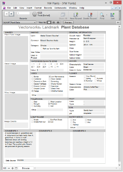
Plant Database RecordsEach plant entry and its associated botanical information is considered a “record” in FileMaker. Several view modes display the records in ways designed to facilitate performing related tasks. When the plant database first opens, the records operate in Browse mode, with Forms displayed.
To familiarize yourself with the different display modes, and view the plant records in a variety of ways:
1 Open the plant database as described in Accessing the Plant Database.
2 Select the View > Status Toolbar database command to enable viewing controls and status at the top of the record form. Many of these items can also be found on the View and Records menu.

3 From the Status toolbar and the View menu, select the view mode and layout options depending on the task to accomplish.
Mode or View Option |
Description |
|---|---|
View Mode |
|
Browse |
Displays plant record information and allows editing |
Find |
Displays a blank form for specifying search criteria |
Preview |
Displays plant record information as it will be printed |
View as Form |
Displays each record as an individual form or “page” |
View as List |
Displays records consecutively in a scrollable list |
View as Table |
Displays each record as an item in a table, for sorting and reordering |
Layout |
|
Data View |
Displays plant record information |
List View |
Displays limited plant data for each plant, for sorting and reordering |
Web View |
Displays a special browser (using the default system browser) for locating plant images and information |
Records Found toggle and status
|
After a search, the green toggle button displays an approximate pie chart and the number of records found; click the green pie chart button to toggle the display to records that are not in the found set. The sort status is also indicated. |
Show All |
Clears the results from a search, displaying all records |
New Record |
Adds a plant record to the database |
Delete Record |
Deletes the currently selected record from the database |
Find |
Switches to Find mode layout, for searching |
Find menu |
Allows searches to be saved, modified, recalled, and cleared |
Sort |
Opens the Sort Records dialog box, for determining the sort order for the plant records, or for unsorting the records |
Quick Find |
Searches for the text entered or recent searches, without switching to Find mode |
Preview |
Displays the records in a Print Preview mode |
~~~~~~~~~~~~~~~~~~~~~~~~~
 Searching
for Plants
Searching
for PlantsThe plant database can be searched from Quick Find in the Status toolbar or by switching the view to Find mode. Quickly search by entering text or repeating a recent search, or conduct flexible, sophisticated searches by combining search criteria. Search criteria can be saved and managed, making it easy to re-create plant lists.
Quick Find searches the plant records for text.

To perform a Quick Find search:
1 Type one or more search terms into the Quick Find field in the Status toolbar.
2 Press Enter.
3 The records that contain the search terms are displayed.
To quickly repeat a previous search, click the Quick Find menu and select the search term used previously.
Find mode performs a more advanced search based on specific criteria. Searches can be saved and managed.

To search for plants in Find mode and manage found sets:
1 Open the plant database as described in Accessing the Plant Database.
2 Select the View > Find Mode database command or click Find from the Status toolbar. Alternatively, select Find > Create New Find.
A blank form opens and the display switches to Find mode. Find mode functions are available from the Status toolbar.
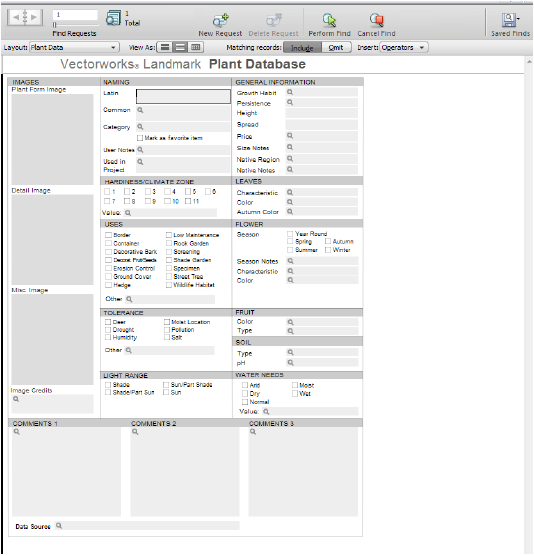
3 Enter the criteria for searching.
Examples include searching for the Latin name “Liatris,” Light Range “Sun,” with a Height > 3–5 ft.
Click the Omit button in the Status toolbar (or select the Omit options from the Records menu) to exclude, rather than search for, the criteria. Use the Operators list for even more specific searches.
4 Click Perform Find from the Status toolbar, or press Enter.
5 The view mode automatically switches to Browse, and the records that meet the search criteria are displayed.
6 To save the current set of search criteria, select Find > Save Current Find.
Other search criteria set maintenance can be performed from the Find menu, to modify, edit, clear, and select saved searches. A previously saved search is executed by selecting its name from the Find menu.
To return to viewing all the plant records, select the Records > Show All Records database command or click Show All from the Status toolbar.
~~~~~~~~~~~~~~~~~~~~~~~~~
 Managing
Plant Database Records
Managing
Plant Database RecordsPlant database records can be edited in Browse mode, whether in form, list, or table view (see Viewing Plant Database Records).
To edit plant records:
1 Open the plant database as described in Accessing the Plant Database.
2 Select the View > Browse Mode database command.
3 Select the plant record to edit by scrolling or searching.
4 Changes made to the fields and check boxes are automatically saved.
Useful edits include:
• Marking a plant as a Favorite (to search for favorite plants later)
• Indicating the Project Information (to track plants by project)
• Adding custom information to drop-down lists
• Placing an image, video, audio, pasted text, or link to an embedded object into one of three containers; right-click an image container to access the options. The images selected here can be synchronized with images selected on the Plant Style: Plant Data Pane.
• Adding image credits and data source information to avoid copyright issues
• Adding extra plant or project information that is useful in the Vectorworks program
Switch between metric and imperial units for the Height and Spread fields with the Edit > Options > Use Imperial Value Lists or Use Metric Value Lists database commands.

Project ID numbers and favorites can easily be added to all plants found by a search, with the Records > Add Project ID and Records > Mark As Favorite database commands. These fields export to the Vectorworks program and are useful for tracking and finding plants. If the Project ID is no longer needed at the completion of a project, search for all plants with that ID and then select the Records > Delete Project ID database command to remove it.
To add a plant to the plant database list:
1 Open the plant database as described in Accessing the Plant Database.
2 Select the View > Browse Mode database command.
3 Select the Records > New Record database command or click New Record from the Status toolbar.
New records are appended to the end of the record set.
4 Enter the plant information. Information is saved automatically.
To remove a plant from the plant database list:
1 Open the plant database as described in Accessing the Plant Database.
2 Locate the record or records to delete, by searching or scrolling.
3 Select the Records > Delete Record database command or click Delete Record from the Status toolbar to delete an individual record, or Records > Delete Found Records to delete a found set of records.
Confirm the deletion; this action cannot be undone.
~~~~~~~~~~~~~~~~~~~~~~~~~
 Accessing Plant Information
from the Internet
Accessing Plant Information
from the InternetIf access to the internet is available, plant images and information are easily obtained from within the plant database window. Images can be copied directly into the database (image credits can also be specified).
To access plant information from the internet:
1 Open the plant database as described in Accessing the Plant Database.
2 Locate the plant record that requires images or information.
3 Select the View > Swap Data View/Web View database command to toggle to web view, or select the Web Data layout from the Status toolbar.
In web view, a search is automatically conducted for the current plant based on its Latin name. Information about it, including images, are displayed from different sources.
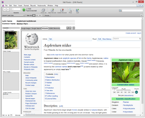
4 Click the web view tabs to find plant information from the various sources. The available sources may depend on regional settings provided by a distributor.
5 Click the buttons to navigate through the web pages of each tab or to reset the view to the initial search (based on the Latin name).

6 To easily copy an image from the internet to the plant database, select Copy (Windows) or Copy Image (Mac) from the image context menu. Then select Paste from the image container context menu. Image credits can be added in the Image Credits area under the images, to avoid copyright issues.
Image files can also be saved and inserted into the database later, as described in Editing Plant Records.
7 Select the View > Swap Data View/Web View database command, or change the layout from the Status toolbar, to return to the database view.
~~~~~~~~~~~~~~~~~~~~~~~~~
 Creating
Plant Catalogs from the Database
Creating
Plant Catalogs from the DatabaseAs described in Concept: Plant Style and Plant Data Integration, the source of plant data for plant styles can either be plant catalogs or the plant database. There are several ways of creating and editing plant catalogs, but one way of creating them is from the plant database.
Creating plant catalogs from the entire set, or from found sets, in the plant database allows you to create a plant catalog with a smaller subset of plants to choose from. Create as many plant catalogs as necessary.
To create a plant catalog from the plant database:
1 Open the plant database as described in Accessing the Plant Database.
2 Search for the plants to include in the plant catalog (see Searching for Plants). The plant catalog is created from a found set of records, or from all the plant records. Larger plant catalogs take longer to load into the Vectorworks program.
3 Select the File > Create Vectorworks Plant Catalog database command.
4 The Create Plant Catalog dialog box opens. Provide a name for the plant catalog.
The plant catalog file is a tab-delimited file saved in the location of the plant database.
Another way of creating a plant catalog from the plant database is to save a found set from the plant database with the Find > Save Current Find database command.
To create plant catalogs based on plant category:
1 Open the plant database as described in Accessing the Plant Database.
2 Select the File > Create Category Plant Catalogs database command.
A plant catalog is created for each category. If there are no plants found for a category, no catalog is created for that category. Plants without a category assigned, or with a custom category, are not included. In addition, an “All” plant catalog contains all plants regardless of category.
The plant catalogs are tab-delimited files saved in the location of the plant database.
By default, all plants in the tree Category of the database are already included (as a plant catalog file) in the Species Data dialog box for access by the Existing Tree tool. If desired, search the plant database for the trees you require, and then add only these trees to the existing tree species catalog.
To create a custom existing tree species catalog:
1 Open the plant database as described in Accessing the Plant Database.
2 Search for the trees to include in the existing tree species catalog (see Searching for Plants).
3 Select the File > Create ‘Existing Tree’ Catalog database command. This customizes the existing tree catalog to use only the plants found in the database search.
~~~~~~~~~~~~~~~~~~~~~~~~~
 Plant
Database Field Mapping
Plant
Database Field MappingWhen plant data is imported into the plant database with the File > Import Records > File database command, field mapping is required (see Importing Plant Database Information). Certain fields must be used during mapping for the plant catalog to function properly when exported for use with the Vectorworks Landmark product. All significant Vectorworks fields have a VW prefix.
The number of available plant data fields varies, depending on global region.
Target Field Name |
Notes or Example Values |
Target Field Name |
Notes or Example Values |
|---|---|---|---|
VW Autumn Color |
|
VW Height |
|
VW Bloom Time |
Also referred to as Season |
VW Landscape Use |
Border, Hedge, Shade Tree... |
VW Category |
Shrubs, Herbs, Trees... |
VW Latin Name |
Also known as the plant botanical name |
VW Climate Zone |
Arid, Semi Arid, Dry... |
VW Light Range |
Deep Shade, Shade, Sun, Full Sun |
VW Code |
|
VW Other Tolerance |
|
VW Comments 1 |
|
VW Other Use |
|
VW Comments 2 |
|
VW Persistence |
Deciduous, Semi-Evergreen, Evergreen... |
VW Comments 3 |
|
VW pH Range |
Acidic, Adaptable |
VW Common Name |
|
VW Price |
|
VW Favorites |
|
VW Region |
|
VW Flower Characteristics |
Double, Erect, Fragrant, Horizontal... |
VW Region Notes |
|
VW Flower Color |
|
VW Season Notes |
|
VW Foliage Characteristics |
Aromatic, Broad-leaf, Evergreen, Fronds, Small leaves... |
VW Size Notes |
|
VW Foliage Color |
|
VW Soil Range |
Bark, Sand, Sandy loam, Potting soil... |
VW Fruit Characteristics |
Acorns, Berry, Catkins, Cones |
VW Spread |
|
VW Fruit Color |
|
VW Tolerances |
Cold Frost, Drought, Heat... |
VW Growth Habit |
Arching, Broad-domed, Columnar, Climber... |
VW Used in Project |
|
VW Hardy Zone |
1–11 (from USDA zone mapping) |
VW User notes |
|
 Plant Graphics
In addition to plant placement with the Plant tool, there are additional ways of representing plant masses on a planting plan. Large, defined planting areas containing specific plants can be created with the Landscape Area tool. Undefined plant masses and groups can be added with the Plant Line and Vegetation Line commands, and the VBvisual Plant tool, which is available in Fundamentals, adds 3D plants. To further change the appearance of the planting plan, all plant styles can be displayed or hidden.
~~~~~~~~~~~~~~~~~~~~~~~~~
 Creating Landscape
Areas
Creating Landscape
AreasTool |
Tool set |
|---|---|
Landscape Area
|
Site Planning |
Landscape areas are defined regions of plant combinations. These can be useful for conceptual landscape planning and for specifying large planting or reforestation areas, when individual plant symbols do not need to be drawn. Plant information from a landscape area is based on plant symbol data, and is included in plant list worksheets. If a site model is present, the landscape area is calculated based on the site model and displays in the Landscape Area Settings dialog box.
A landscape area can also be created without plant information specified, for use as a general ground cover or mulch area with a label showing the total area required.
Landscape areas are created with the Landscape Area tool, which offers several modes for defining the areas. Landscape area objects can also be created by drawing a polyline and then selecting the Create Objects from Shapes command (see Creating Objects from Shapes).
|
Click here for a video tip about this topic (internet access required). |

Mode |
Description |
|---|---|
Insertion |
Draws a landscape area using the selected polyline creation options and the current preference settings |
Pickup |
Picks up the settings and attributes of an existing landscape area and makes those the default preference settings for subsequently created objects. The landscape area’s Name parameter is given a suffix with sequential numbers for new landscape areas. |
Bucket |
Converts an existing polyline, polygon, rectangle, circle, or arc to a landscape area and applies the current preference settings |
Landscape Area |
Opens the Resource Selector to select a resource for placement; double-click a resource to activate it |
Polyline creation options |
Selects the method for drawing the polyline upon which the object is based; see Creating Polylines |
Preferences |
Opens the Landscape Area Settings dialog box to set the default preferences for landscape areas |
To create a landscape area:
1 Click the tool.
2 Do one of the following:
• To use an existing landscape area from the resource libraries, click Landscape Area on the Tool bar. From the Resource Selector, double-click a resource to activate it.
• To create a custom landscape area, click Preferences. From the Landscape Area Settings dialog box, set the default properties. The properties can be edited from the Object Info palette.
To apply the settings from an existing landscape area in the drawing, click Pickup mode from the tool bar and then click on the landscape area from which to pick up settings. Create the new landscape area either by drawing it using the Insertion mode and appropriate polyline creation options or by clicking Bucket mode from the Tool bar and then selecting an existing polyline, polygon, rectangle, circle, or arc to convert into a landscape area. The picked up settings are automatically applied to the new landscape area.
► Clique para exibir/ocultar parâmetros.
3 Click Add or select a plant from the Plant list and click Edit to open the Edit Plant Information dialog box and specify the plants included in the landscape area, as well as their frequency.
► Clique para exibir/ocultar parâmetros.
4 Click OK, and then click OK again to close the Landscape Area Settings dialog box.
5 Click the appropriate mode in the Tool bar to select the boundary creation method of the landscape area.
For more information on the Polyline tool modes, see Creating Polylines.
6 Click to set the landscape area’s start point.
7 Click to set the end of the segment and the beginning of the next. Continue drawing segments in this manner until the landscape area object is complete.

To save the landscape area settings as a resource for future landscape areas, click Save Landscape Area on the Object Info palette and enter a name for the landscape area resource.
The appearance of the landscape area is controlled by several methods.
• Change the landscape area parameters from the Object Info palette, including specifying a general unit price (for indicating the price per square unit in worksheets), price code (such as a SKU number) and vertex parameters; click Landscape Area Settings from the Object Info palette to change landscape area information and other preference parameters
• Change the landscape area 2D attributes from the Attributes palette
• Change the landscape area tag appearance by editing its parameters from the Object Info palette, editing the tag class properties, and/or moving tag control points (similar to a plant tag; see Plant Tag Appearance)
• To align landscape area tags for improved readability, use the Align/Distribute Leader Lines command (see Aligning and Distributing Leader Lines)
• Reshape the landscape area by double-clicking on it; the Reshape tool is automatically activated, to reshape the object directly in the drawing
• Right-click on the landscape area object and select Edit from the context menu. The Edit Landscape Area dialog box opens. Either edit the settings of the selected landscape area, or edit the shape of the object path with the Reshape tool.
~~~~~~~~~~~~~~~~~~~~~~~~~
 Creating a Custom
Landscape Area Tag
Creating a Custom
Landscape Area TagIn addition to providing several predefined landscape area tags, Vectorworks Landmark allows designers to create custom landscape area tags.
1 From the Tag Information pane of the Landscape Area Settings dialog box, select Set Custom Tag from either the Tag Header or Tag Body fields. Settings for the landscape area tag currently displaying in this field are displayed in the Set Custom Tag dialog box.
The Set Custom Tag dialog box opens.
If editing an existing tag through the Object Info palette, the selected tag’s data displays.
2 Select values from predefined landscape area values and plant record fields in the order they should be listed, and type the delimiter text to place between the fields. Select <New Line> to start the next tag item on a new line. A combination of up to six landscape area values, plant record fields, and line breaks can be used.
The Tag Appearance field displays a static text preview of the custom tag. To preview a long tag in its entirety, click-drag the bottom right corner of the dialog box to resize it.
~~~~~~~~~~~~~~~~~~~~~~~~~
 Creating Landscape Area Schedules
Command |
Path |
|---|---|
Create Report |
Tools > Reports |
Preformatted schedules are available to report landscape area information for your file.
To create landscape area schedules:
1 Select the command.
The Create Report dialog box opens.
2 Select a schedule, and click the drawing area to place it. If you select the hydrozone or water budget schedule, the Hydrozone record format is also added.
• Landscape Area-Mass Planting (with or without images) lists the area names and sizes, and the names, percentages, and spacing of each type of plant in the area
• Landscape Area-Hydrozone Information lists general hydrozone information about each area
• Landscape Area-Water Budget lists plant type, plant factor, maximum water allowance, and estimated water use for each area
3 If you selected the hydrozone or water budget schedule, attach hydrozone data to each landscape area.
• Select a landscape area, and then from the Object Info palette, click the Data tab.
• Click Attach Record. From the Resource Selector, double-click the Hydrozone record format to apply it. The fields for the record format display below the Detach Record button.
• Enter the appropriate value for each field.
4 If you selected the hydrozone or water budget schedule, right-click the worksheet in the drawing, and select Recalculate from the context menu.
~~~~~~~~~~~~~~~~~~~~~~~~~
 Creating a
Plant Line
Creating a
Plant LineCommand |
Workspace: Path |
|---|---|
Plant Line |
• Designer: AEC > Plants • Landmark: Landmark |
The Plant Line command creates a freehand plant line along a line, polyline, or polygon. It can be used to represent a single undefined plant, line of plants, or general plant mass. No specific plant symbol information is included in a plant line; use the Landscape Area tool if defined plant areas are necessary (see Creating Landscape Areas).
To create a plant line:
1 Select the object (line, polyline, or polygon) with the Selection tool.
2 Select the command.
The Plant Line dialog box opens. Suggested values are based on the selection’s perimeter.
► Clique para exibir/ocultar parâmetros.
3 Select the desired plant line parameters. The plant line is created. If desired, apply colors, textures, and other attributes to the plant line with the Attributes palette.

~~~~~~~~~~~~~~~~~~~~~~~~~
 Creating a
Vegetation Line
Creating a
Vegetation LineCommand |
Workspace: Path |
|---|---|
Vegetation Line |
• Designer: AEC > Plants • Landmark: Landmark |
The Vegetation Line command creates a vegetation line around a selection of closed objects or symbols. It can be used to represent a massed collection of undefined vegetation.
To create a vegetation line:
1 Select the closed objects or symbols that will form the basis of the vegetation line. The items should overlap.
2 Select the command.
The Vegetation Line dialog box opens. Select the type of vegetation line to create, and whether the original objects should be deleted or retained.
► Clique para exibir/ocultar parâmetros.
3 If desired, apply colors, textures, images, hatches, gradients and other attributes to the vegetation line with the Attributes palette. See The Attributes Palette for more information on applying attributes.

The vegetation line can be assigned to a class (with the desired attributes). The original plant symbols can remain hidden by a vegetation line with a solid fill; however, the underlying vegetation can be revealed by hiding the vegetation line class.
 Show
or Hide Plant Details
Show
or Hide Plant DetailsCommand |
Path |
|---|---|
Show or Hide Plant Details |
View > Show |
The Show or Hide Plant Details command controls the visibility of the outline, massing, and shadow parameters set on the Visualization pane of a plant style (see Plant Style: Visualization Pane), on the Visualization pane of the plant preferences (see Advanced Plant Preferences: Visualization Pane), as well as from the Object Info palette.
These effects display in Top/Plan view only. In a complex drawing with many plants, these settings can take a significant amount of time to display and edit, and it is useful to toggle the effects on and off.
To show or hide the plant details:
Select the command.
If the plant details are currently hidden, this command displays the outline, massing, and shadows of all plant objects with those parameters set. If the plant details are currently visible, this command hides the effects. The Outline selection is saved for the plants, even when hidden.
Tool |
Tool set |
|---|---|
VBvisual Plant
|
Visualization |
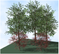
Many designs have a need for plants that render quickly and appear more realistic than image prop objects. High-quality 3D plants from VBvisual (makers of 3D content for rendering packages) are available. These plants look authentic in all views and cast realistic shadows, without adding excessively to rendering times or file size. More plants can be purchased to add to the library of 3D plants.
To place a 3D plant:
1 Click the tool, and then select the plant to insert from the VBvisual Plant list on the Tool bar.
2 Click to insert the selected plant into the drawing.
When applicable, the low resolution, summer version of the plant is inserted by default. The plant includes a 3D locus so it can be easily moved; in addition, the plant can be sent to the surface of a site model (see Sending Objects to the Site Model Surface). In Top/Plan view, a 2D version of the plant displays.
The object properties can be edited from the Object Info palette. The options available depend on the selected plant type.
► Clique para exibir/ocultar parâmetros.
More plants are available for purchase in Vectorworks file format from VBvisual. Select More Plants from the VBvisual Plant list. Purchased plants must be placed in the default content library folder named VBvisual Plant (see Concept: Resource Libraries).
~~~~~~~~~~~~~~~~~~~~~~~~~
 Documenting
Existing Trees
Documenting
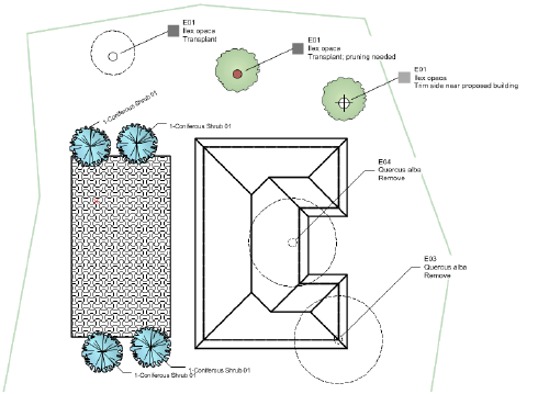
Existing TreesThe Vectorworks Landmark product includes the Existing Tree tool, for documenting the existing trees on a site. Details about each tree can be provided, including information such as species, condition, life expectancy, significance, and action to be taken. The 2D and 3D appearance of the trees can be specified, indicating the root and tree protection zones, with detailed plant ID tags and graphics for retained and removed trees, and the ability to select a 3D trunk and canopy shape.
Existing trees can be created automatically from survey file information, or from loci.
To report the tree data in a worksheet, use the “Existing Tree Schedule” (with or without images); see Using Preformatted Reports.
|
Click here for a video tip about this topic (internet access required). |
~~~~~~~~~~~~~~~~~~~~~~~~~
 Workflow:
Existing Tree Placement
Workflow:
Existing Tree PlacementWhen placing existing trees into the drawing, the following workflow is recommended:
• Choose whether to use the plant catalog or the database by Selecting the Plant Data Source.
• Click the Existing Tree tool from the Site Planning tool set, and then select Preferences to open the Object Properties dialog box for the existing tree. Set the defaults for the placement of existing trees, including automatic numbering, ID tag, 2D and 3D appearance (including the selection of 2D component symbols), and species information.
• While setting the default properties for the Existing Tree tool, specify classing wherever possible to be able to control the visibility of classed elements (easily accomplished from the Navigation palette) as well as specify appearance by class for many of the elements.
• Select Tools > Organization to open the Organization dialog box. On the Classes tab, navigate to the classes related to the existing tree, and specify their appearance. Classes should be set to Use at Creation. For canopy and trunk classes, set the texture or color to display in 3D views. Set the marker and line style of the tag class if a marker is to be displayed.
• When importing existing trees from a survey file, or creating existing trees from loci, map the fields to the records and choose the units appropriately to successfully create the trees.
• When placing existing trees, keep in mind that the selected 2D component symbols will not display until an Action has been specified. This helps you determine at a glance which trees still require an action to be set.
• The parameters of groups of selected trees, or trees on a specific layer, or all trees can be set in a single operation by using the Apply Properties in the various existing tree dialog boxes.
• Indicate the location of important and less important areas of the site by specifying the significance of each tree or group of trees.
• Existing tree data can be used to create a worksheet, which can then be exported to create a tree survey text file.
• Loci with existing tree information can be exported in shapefile format, including the existing tree information in the attached record.
~~~~~~~~~~~~~~~~~~~~~~~~~
 Importing
Existing Trees from a Survey File
Importing
Existing Trees from a Survey FileCommand |
Path |
|---|---|
Import Tree Survey |
Landmark > Existing Trees |
Survey file tree data can be imported into Vectorworks Landmark, and then used to automatically create existing trees with the proper attached information, including location. By mapping the attached data to the existing tree parameters and to record fields, valid existing tree objects are created in the file with all the survey data incorporated. After modification, data from an existing tree schedule can then be exported as a tree survey text file.
If desired, loci with attached record data can be created instead. The loci with the tree information can then be exported in shapefile format.
To import existing trees from a survey file:
1 Select the command.
2 Select the survey file to import.
The Import Tree Survey dialog box opens. Specify how to import the tree survey data and how to map the data to the existing tree parameters in the Vectorworks file. The settings can be saved for future use.
► Clique para exibir/ocultar parâmetros.
3 Select each row of the survey mapping table, and then specify how it should be mapped to the equivalent existing tree parameter by selecting it from the Selected Existing Tree Parameter. If necessary, select the specific units that should be used if they are different from the document defaults. If the row data should be added to a custom record, place a check mark in the row.
When mapping to existing tree parameters, the associated data values are mapped directly when the type is compatible. For example, when the height parameters are mapped, the height value from the survey file becomes the Height value for the existing tree; a mapped Condition parameter is set as expected if the entry matches one of the default options (Excellent, Good, Average, Poor), or to Custom if the entry does not match the defaults.
If no data are provided for mapped parameters, the default values of the Existing Tree tool are used.
There are some existing tree parameters for which there is no survey data equivalent; these parameters are also set to their defaults upon creation of the existing tree object.
4 Save the mapping settings if needed.
5 Click OK to import the survey data.
~~~~~~~~~~~~~~~~~~~~~~~~~
 Creating
Existing Trees from Loci
Creating
Existing Trees from LociCommand |
Path |
|---|---|
Create Existing Trees from Loci |
Landmark > Existing Trees |
Loci with tree survey data, which may have come from a survey file, imported DXF/DWG file, or point-based shapefile, can be converted to existing tree objects with the proper attached information, including location. By mapping the attached data to the existing tree record fields, valid existing tree objects are created in the Vectorworks Landmark file.
To create existing trees from loci:
1 Select the loci, or select symbols that contain the loci.
2 Select the command.
The Create Existing Trees from Loci dialog box opens.
► Clique para exibir/ocultar parâmetros.
3 If using a record attached to loci as the basis of the existing tree parameters, select the record, and then select each row of the record mapping table. Specify how each row should be mapped to the equivalent existing tree parameter by selecting it from the Selected Existing Tree Parameter. If necessary, select the specific units that should be used if they are different from the document defaults.
When mapping to existing tree parameters, the associated data values are mapped directly when the type is compatible. For example, when the height parameters are mapped, the height value from the record becomes the Height value for the existing tree; a mapped Condition parameter is set as expected if the entry matches one of the default options (Excellent, Good, Average, Poor), or to Custom if the entry does not match the defaults.
If no data are provided for mapped parameters, the default values of the Existing Tree tool are used.
4 Save the mapping settings if needed.
5 Click OK to create the existing tree objects from the loci.
~~~~~~~~~~~~~~~~~~~~~~~~~
 Placing
Existing Trees
Placing
Existing TreesTool |
Tool set |
|---|---|
Existing Tree
|
Site Planning |
To place an existing tree:
1 Click the tool.
2 Click to place the object in the drawing, and click again to set the rotation.
The first time you use the tool in a file, a properties dialog box opens. Set the default properties. The properties can be edited from the Object Info palette.
The appearance of the existing tree may not match its 2D settings until certain parameters have been specified from the Object Info palette. For example, until the Action is specified, the tree does not display with the symbol set for Retain or Remove; the significance must be set for the significance color to display.

► Clique para exibir/ocultar parâmetros.
~~~~~~~~~~~~~~~~~~~~~~~~~
 Specifying
Existing Tree Species Information
Specifying
Existing Tree Species InformationThe species information for existing trees is selected from a plant catalog. The list of trees can be edited.
The plant catalog file is the Existing Trees.txt file located in the user folder. It can be customized from the plant database; see Creating Plant Catalogs from the Database.
To specify existing tree species and select a species:
1 From the Object Info palette of a selected existing tree, click Get Species Data.
The Species Data dialog box opens, listing tree species information. Species can be easily added to the list.
► Clique para exibir/ocultar parâmetros.
2 Select the species from the list, and click OK.
The Object Info palette displays the species information.
~~~~~~~~~~~~~~~~~~~~~~~~~
 Setting
2D Existing Tree Appearance
Setting
2D Existing Tree AppearanceThe 2D appearance controls the symbol for the tree and trunk, and also sets the attributes of the significance status, primary and critical root zones, and tree protection zones. The settings apply to the selected tree or a variety of other selection options, and can be set as the default 2D attributes for the drawing. This is a powerful way to control the 2D appearance of all existing trees in the layer or drawing in one operation.
Using classes for the significance colors, root zone, and tree protection zone is recommended. The visibility of these elements is easy to control with classes. See Concept: Classes Overview.
Existing tree symbols are provided in libraries; a selected symbol is automatically imported into the current file and displays in the Resource Manager. The resources in the ET Symbols.vwx file are available in the 2D Properties dialog box.
To set the existing tree 2D appearance:
From the Object Info palette of a selected existing tree, select 2D Properties. Alternatively, double-click an existing tree. The 2D Properties dialog box opens to set the parameters.
► Clique para exibir/ocultar parâmetros.
Certain 2D properties depend on selections made from the Object Info palette for each existing tree, and are not applied immediately. For example, the symbol specified in Tree Remove does not display unless Remove is selected as the Action for the tree.
The symbols for retained and removed trees are scaled by the canopy height and diameter specified from the Object Info palette. The original and proposed symbols for a transplanted tree are scaled by the DBH parameter.
~~~~~~~~~~~~~~~~~~~~~~~~~
 Specifying
the Tree Protection Zone
Specifying
the Tree Protection ZoneThe tree protection zone is the area around the tree that should be fenced off, or preserved, to protect the tree. The tree protection zone moves with the tree trunk location. The zone can be irregular or circular; irregular zones can be reshaped. The TPZ Area displays the calculated area for the entire tree protection zone.
To specify the tree protection zone:
From the Object Info palette of a selected existing tree, select the type of Tree Protection.
► Clique para exibir/ocultar parâmetros.
An irregular tree protection zone may need to extend beyond the initial boundary shape. To reshape the tree protection zone:
1 Select Edit Irregular Zone from the Tree Protection parameter.
The tree protection zone displays with editing handles.

2 Drag the handles to reshape the zone. Adjust the radius at the corners of the zone with the TPZ Cnr Radius value, which only displays during zone editing.
3 When reshaping is finished, select Display Irregular Zone from the Tree Protection parameter.
~~~~~~~~~~~~~~~~~~~~~~~~~
 Specifying
an Irregular Canopy
Specifying
an Irregular CanopySince trees are not always perfectly symmetrical, the Existing Tree tool allows an irregular canopy shape to be defined by setting the measurements, in four different directions, from the center of the trunk to the edge of the canopy.
If the trunk had previously been repositioned by moving its control point, it is reset to the default position when an irregular canopy is selected. The trunk cannot be offset for irregular canopy shapes.
To specify an irregular canopy shape:
From the Object Info palette of a selected existing tree, select Irregular Canopy Size. The Irregular Canopy Size dialog box opens. Specify the canopy size in four directions.
► Clique para exibir/ocultar parâmetros.
The 2D and 3D appearance of the tree displays with an irregular canopy shape, roughly based on the selected symbol definition.
The irregular shape can be oriented differently by entering a North Angle offset from the Object Info palette.
~~~~~~~~~~~~~~~~~~~~~~~~~
 Setting
3D Existing Tree Appearance
Setting
3D Existing Tree AppearanceThe 3D appearance controls the symbol for the tree and trunk in 3D views. The settings apply to the selected tree or a variety of other selection options, and can be set as the default 3D attributes for the drawing. This is a powerful way to control the 3D appearance of all existing trees in the layer or drawing in one operation. Showing trees in a 3D view is also useful for creating shadow diagrams.

Using classes for the tree canopy shape and trunk is recommended. The attributes (color or texture) of these elements are easy to control with classes. The class color or texture must be set to Use at Creation. See Concept: Classes Overview.
Existing tree symbols are provided in libraries; a selected symbol is automatically imported into the current file and displays in the Resource Manager. The resources in the ET Symbols.vwx file are available in the 3D Properties dialog box.
Image props, such as those provided by xFrog, can be used as 3D tree geometry. However, canopy height and canopy diameter changes from the Object Info palette do not affect the geometry of image props.
To set the existing tree 3D appearance:
From the Object Info palette of a selected existing tree, select 3D Properties. The 3D Properties dialog box opens.
► Clique para exibir/ocultar parâmetros.
The 3D canopy shape is affected by changes in the Object Info palette for height, diameter, irregular canopy shape, First Branch Hgt, and DBH values.
~~~~~~~~~~~~~~~~~~~~~~~~~
 Existing Tree Autonumbering and
ID Tags
Existing Tree Autonumbering and
ID TagsExisting tree tags can contain an automatic numbering ID as well as tree information. Set up the new tree autonumbering properties first, to automatically number the trees according to the settings as they are placed on the drawing. Autonumbering can also be changed after placement on a tree-by-tree basis.
To set autonumbering and ID tag information for existing trees:
From the Object Info palette of a selected existing tree, select Tag and Number Options. The Tag and Number Options dialog box opens.
► Clique para exibir/ocultar parâmetros.
Existing tree tag appearance and placement is flexible, and can be adjusted in several ways, including through the Object Info palette, tag class settings, and the control point locations on the drawing.
• When existing tree tags are required, define their appearance in the Tag and Number Options dialog box. Apply the ID tag options to all existing trees and to the document defaults.
• Individual tags can then be changed for selected existing trees by clicking Tag and Number Options from the Object Info palette. For example, selected trees in one area of a planting plan look more uniform when they all use the same tag approach and tag shoulder angle. Set the Shoulder Angle and then select Also apply position of ID tag.
• The existing tree tag class controls the appearance of the leader/shoulder lines, as well as the marker style.
• To move the plant tags of several selected plants at once, click the Unrestricted Interactive Scaling mode of the Selection tool.
• If an individual tag needs to be repositioned, plant tags also have several control points for adjusting the tag text and leader line and shoulder position and angle.
• Align and distribute the leader lines for improved readability with the Align/Distribute Leader Lines command (see Aligning and Distributing Leader Lines)

~~~~~~~~~~~~~~~~~~~~~~~~~
 Customizing
Existing Trees
Customizing
Existing TreesExisting trees are hybrid symbols, containing a 2D symbol component, and optionally, a 3D symbol component. The default existing tree symbols are located in the default content included with the Vectorworks Landmark product in Vectorworks\Libraries (see Concept: Resource Libraries). As 2D and 3D settings are made, the associated tree symbols are automatically imported into the current file and appear in the Resource Manager.
As with any resource, the symbols can be edited through the Resource Manager, and these edits apply to the current file. Alternatively, custom existing tree symbols can be added to the default ET Symbols.vwx file, either directly or by exporting edited tree symbols to the file (duplicate and rename the symbols from the Resource Manager first, so that the original symbols are not overwritten). For more information on symbol operations in the Resource Manager, see Resource Manager. See Exporting Resources for information on exporting resources.
These naming conventions ensure that any custom symbols are available for selection in the 2D and 3D Properties dialog boxes:
• Symbol names for retained trees, or the new location of transplanted trees, must begin with 1. (the number 1, followed by a period)
• Symbol names for removed trees, or the original location of transplanted trees, must begin with 2.
• Symbol names for the 2D tree trunk must begin with 3.
• Symbol names for the 3D canopy must begin with 4.
~~~~~~~~~~~~~~~~~~~~~~~~~
 Adding Foliage
Tool |
Tool set |
|---|---|
Foliage
|
Visualization |
The Vectorworks Landmark product includes the Foliage tool, for creating hedges, topiaries, vertical plantings, and ground cover, using custom geometry, and following the site model surface where applicable.
A foliage object is a collection of foliage type symbols, such as leaves or flowers. You can control the type, number, and orientation of the foliage symbols to create the best effect.
Define the shape of the foliage by drawing a polyline, which is converted into a 3D shape according to the selected configuration mode. Foliage objects can also be created by drawing a polyline and then selecting the Create Objects from Shapes command (see Creating Objects from Shapes).

Mode |
Description |
|---|---|
Configuration |
Specifies how the foliage object will be configured, as described in the following section |
Symbol |
Opens the Resource Selector; double-click a resource to select it. You can also specify a folder that contains a group of symbols; the foliage will be created by randomizing the symbols inside the group. After the foliage object is created, you can select an additional symbol from the Object Info palette, to add flowers to a hedge, for example. |
Polyline creation options |
Selects the method for drawing the polyline upon which the object is based; see Creating Polylines |
Preferences |
Opens the Foliage Tool Preferences dialog box to set the parameters for the foliage object |
1 Click the tool, and then click Symbol on the Tool bar to specify the symbol to use for the foliage object. From the Resource Selector, double-click a resource to activate it.
2 Click Preferences to open the Foliage Tool Preferences dialog box. Different parameters display depending on the Configuration type. The Foliage tool uses these preferences until they are changed.
► Clique para exibir/ocultar parâmetros.
3 Click the appropriate mode on the Tool bar to draw the polyline shape for the foliage object.
For more information on the Polyline tool modes, see Creating Polylines.
4 Click to set the foliage object’s start point.
5 Click to set the end of the segment and the beginning of the next. Continue drawing segments in this manner until the foliage object path or profile is complete.
After the foliage object has been created, edit the foliage object from the Object Info palette, or select Properties from the object’s context menu to open the Properties dialog box. The same parameters that are available on the Foliage Tool Preferences dialog box display, along with the following additional parameters.
► Clique para exibir/ocultar parâmetros.
To reshape the path or profile of a foliage object, right-click and select Edit Path or Edit Profile from the object’s context menu. Alternatively, double-click the foliage object.

 Creating
a Foliage Symbol Definition
Creating
a Foliage Symbol DefinitionTool |
Tool set |
|---|---|
Foliage
|
Visualization |
You can create a custom foliage symbol definition from an image file.
To create a foliage symbol definition:
1 Select an existing foliage object for which you want to create a new symbol definition.
2 From the Object Info palette, click Create Symbol. The Create Foliage Symbol dialog box opens.
► Clique para exibir/ocultar parâmetros.
The symbol definition is applied to the selected foliage object.
3 To save the symbol definition for reuse in other files, use the Resource Manager’s Export command to export the symbol definition to a file in the Defaults\Foliage folder in your user folder.
~~~~~~~~~~~~~~~~~~~~~~~~~
 Covering
a Solid with Foliage
Covering
a Solid with FoliageTool |
Tool set |
|---|---|
Foliage
|
Visualization |
If you add a 3D solid object to the profile of a foliage object, the foliage takes on the shape of the solid. This can be useful for creating topiary effects.
To cover a solid object with foliage:
1 Copy the solid object to be covered to the clipboard.
2 Click the tool; from the Tool bar, select a foliage symbol, and then create a foliage object using any configuration type.
3 From the Object Info palette, change the Configuration setting for the foliage object to Cover 3D Generic Solid. The foliage object is converted into a sphere shape.
4 From the Object Info palette, click Edit Profile. The profile editing window opens, showing the sphere and two polygons that define the foliage object.
5 Paste the solid object from your clipboard into the editing window, and then delete the sphere.
6 Click Exit Profile to close the editing window and update the foliage object.

~~~~~~~~~~~~~~~~~~~~~~~~~