Focusing
InstrumentsFocusing
Instruments
Focusing
InstrumentsFocusing
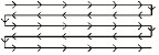
InstrumentsTo focus a lighting instrument assembly and beam on a particular area or object, a focus point needs to be defined.
The focus point can also be used to create Magic Sheets that show the instruments focused on a particular area (see Magic Sheets). In addition, the focus point can be used as one of the criteria for finding instruments with the Find and Modify command (see Find and Modify). It is also possible to select all lighting devices assigned to a particular focus point for quick editing (see Editing Lighting Instruments).
Focused instruments can automatically point towards their focus point in 2D views; see Spotlight Setup.
Tool |
Tool set |
|---|---|
Focus Point
|
Lighting |
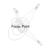
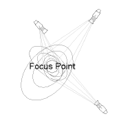
An object defined as a focus point specifies where instrument assemblies and light beams should be directed. If the focus point is moved, any instruments that are aimed at it update their focus position based on the focus point information.
Like hanging positions and instruments, focus points should be inserted on their own design layer, to facilitate selection, viewing, and printing. Alternatively, it is acceptable to insert the focus points on the same design layer as the scenic elements. Focus points can also be inserted into their own classes.
A 3D stage object can be used as a focus point for lighting instruments by naming it as the focus point in the instrument Object Info palette (see Lighting Device Properties).
To create a focus point object:
1 Click the tool, and then click Preferences to specify the default focus point settings. These settings can be changed later for existing focus points from the Object Info palette.
The Focus Point Properties dialog box opens.
► Clique para exibir/ocultar parâmetros.
2 Click the plot to insert the focus point object.
3 The Place Focus Point dialog box opens. Enter the name of the focus point, and the focus height above the stage floor. The focus point name is required later to specify the focus point for the lighting instruments.
The name of a focus point can be changed on the Data tab of the Object Info palette, and can be updated in the drawing file by selecting Reset on the Shape tab of the Object Info palette. Place focus points in their own class so they can be easily hidden for a 3D rendering. Alternatively, select Standard 2D or Locus Points Only for the Focus Point Shape.
~~~~~~~~~~~~~~~~~~~~~~~~~
 Assigning
a Focus Point to a Lighting Instrument
Assigning
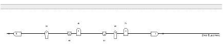
a Focus Point to a Lighting InstrumentOne or more instruments and/or multi-circuit instruments can be focused on a focus point. The focus point is used to draw light beam representations (see Drawing Light Beam Representations), calculate photometric values (see Obtaining Photometric Data), and for rendering gobo projections (see Gobo Projection Requirements). In 3D views, the instrument rotates to point automatically at the focus point.
Command |
Path |
|---|---|
Focus Instruments at Next Click |
Document context menu |
To focus the lighting instrument at the next click:
1 Select the instrument.
2 Select the command.
3 To create a new focus point for the instrument, click in the drawing. The current focus point properties are used, and a unique name is automatically assigned to the new focus point; see Creating a Focus Point Object. Alternatively, click an existing focus point or locus.
The instrument to assigned to the new or existing focus point.
If you place a new focus point on an existing 3D object while in a 3D view, the focus point automatically adopts the Z value of the click.
Command |
Path |
|---|---|
Focus Instruments |
• Spotlight • Context menu |
To focus the lighting instrument with the menu command:
1 Select the instrument.
2 Select the command.
The Focus Instruments dialog box opens. Select an existing focus point, or select Next Click to create a new focus point with the next mouse click.
If Next Click is selected, the New Focus Point dialog box opens. Specify the name and height of the focus point.
To change the focus point of a single instrument, enter the name of the new focus point in the Focus field of the Object Info palette (see Lighting Device Properties).
~~~~~~~~~~~~~~~~~~~~~~~~~
 Drawing
Light Beam Representations
Drawing
Light Beam RepresentationsOnce the focus point for instruments has been specified, light beam representations can be drawn. Wireframe light beam representations can be controlled by class; see Lighting Device Setup.
To turn on the light beam for one or more instruments:
1 Select the instruments.
Use the Select Focused Lighting Devices context menu to quickly select all lighting devices assigned to a focus point (see Changing Device Properties).
An instrument must have a focus point in order to draw a light beam representation (see Assigning a Focus Point to a Lighting Instrument). Elliptical light sources require secondary beam and field angles. The Focus Instruments command inserts a default falloff distance for elliptical light sources.
2 Select Draw Beam from the instrument Object Info palette (see Lighting Device Properties).

An accurate wireframe representation of the light beam’s spread and location on the stage is drawn, oriented to the focus point. The light beam of instruments used for general wash lighting can also be drawn; however, a focus point is still required in order to draw the light beam representation.
3 Select Draw Beam as 3D Solid from the instrument Object Info palette to see the light beam as a solid cone of light. The Color specified in the Object Info palette or Lighting Device dialog box determines the solid color (see Lighting Instrument Color). The class of the light beam can also determine its appearance and optionally, texture.
~~~~~~~~~~~~~~~~~~~~~~~~~
 Obtaining
Photometric Data
Obtaining
Photometric DataVectorworks can determine and display the approximate amount of light at a point on the stage at a specific elevation (Photometer object) or along a grid (Photometric Grid object). The pen color of each indicator provides a visual cue of the light intensity according to defined ranges.
The photometric tools use the Candlepower parameter in the Light Info record to determine the lighting intensity.
For photometric values to be measured, the lighting instruments must have a designated focus point.
~~~~~~~~~~~~~~~~~~~~~~~~~
 Inserting
a Photometric Grid
Inserting
a Photometric Grid Tool |
Tool set |
|---|---|
Photometric Grid
|
Lighting |
The photometric grid is a is a three-click rectangular object, and can be inserted in Center-line Placement mode or Edge Placement mode. The grid can be tilted, accounting for sloped or raked stages.

Mode |
Description |
|---|---|
Center-line Placement |
Click once, and then again, to define the length through the center of the grid. Click again to specify the grid width. |
Edge Placement |
Click once, and then again, to define the length along the edge of the grid. Click again to specify the grid width. |
Preferences |
Sets the default preferences for the photometric grid |
To insert a photometric grid:
1 Ensure that each lighting instrument contributing to the illumination is focused.
The light beams do not have to be drawn for calculations to be made.
2 Click the tool and a placement mode.
3 Click in the drawing area to insert the photometric grid.
The first time you use the tool in a file, a properties dialog box opens. Set the default properties. The properties can be edited from the Object Info palette.
► Clique para exibir/ocultar parâmetros.
After placing the photometric grid, set the grid’s Z value from the Object Info palette; illumination values vary depending on the grid’s elevation.
~~~~~~~~~~~~~~~~~~~~~~~~~
 Inserting
a Photometer
Inserting
a Photometer Mode |
Tool |
Tool set |
|---|---|---|
Modes for The Symbol Insertion Tool |
Photometer
|
Lighting |
To insert a photometer:
1 Ensure that each lighting instrument contributing to the illumination is focused.
The light beams do not have to be drawn for calculations to be made.
2 Click the tool and modes.
3 Click to place the object in the drawing, and click again to set the rotation.
The first time you use the tool in a file, a properties dialog box opens. Set the default properties. The properties can be edited from the Object Info palette.
► Clique para exibir/ocultar parâmetros.
After placing the photometer, set its Z value from the Object Info palette; illumination values vary depending on the photometer’s elevation.
~~~~~~~~~~~~~~~~~~~~~~~~~
 Using Photometric Threshold Settings
Vectorworks’ photometric grid and photometer calculate and display the illumination values at the elevation point. The values are displayed in either foot candles (Imperial) or lux (Metric), depending on the units selected in File > Document Settings > Units. The pen color of each indicator provides a visual cue of the light intensity according to defined ranges, which are specified here.
To specify threshold settings:
1 From the Object Info palette of either a photometric grid or photometer, click Threshold Settings.
The Threshold Settings dialog box opens.
► Clique para exibir/ocultar parâmetros.
2 To evaluate the illumination values at different heights, change the elevation of the photometric object in the Object Info palette.


~~~~~~~~~~~~~~~~~~~~~~~~~
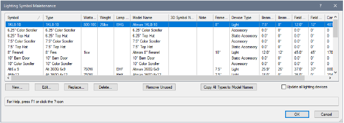
 Lighting Symbol Maintenance
 Command |
Path |
|---|---|
Lighting Symbol Maintenance |
Spotlight > Reports |
Manage, edit, and update the symbols and data for all the lighting symbols in the file from a single location. Easily spot inconsistencies and missing data, and fix the issues for all existing symbols or just for future symbol placement.
To maintain the data and symbols for all the lighting symbols in the file:
1 Select the command.
The Lighting Symbol Maintenance dialog box opens.
► Clique para exibir/ocultar parâmetros.
2 If any lighting instrument data has changed, but Update all lighting devices is not selected, an alert message displays when you click OK.
Click Yes to update all existing and future symbol instances in the file. Select No to update only future symbol instances.
 Lighting Inventory Setup
Command |
Path |
|---|---|
Lighting Inventory Setup |
Spotlight > Reports |
The current status of available lighting device inventory is specified with the Lighting Inventory Setup command. The number of available devices can be included in instrument summaries.
To establish and maintain inventory counts:
1 Select the command.
The Lighting Inventory Setup dialog box opens.
2 Select each device type row, and enter the number of available instruments in the Quantity.
The devices can be sorted by clicking in the Type column header.
3 Unused lighting devices can be removed from the inventory. Select the device to remove, and click Remove; the Light Info (or Light Info M) record is removed from the symbol selected in the list, and the device is removed from the inventory list. The symbol is not removed from the file, but the symbol no longer appears in reports about the lighting device.
Lighting device symbols that are deleted from the drawing are automatically removed from the inventory.
The inventory report can be included as a report when generating paperwork.
~~~~~~~~~~~~~~~~~~~~~~~~~
 Creating
Instrument Summaries
Creating
Instrument SummariesStatistics on the instruments and accessories used in the light plot help with event organization. Instrument summaries can be created for the all instruments (see Creating an Instrument Summary), and/or for specific hanging positions (see Creating an Instrument Summary for a Hanging Position). The summary, which can be custom formatted, can show the symbol thumbnail and name, the number of each kind of instrument and accessory in use, display total counts, and add special elements like notes, column breaks, circuit summaries, typical label legend layout, and other items. Counting can be subtotaled to count instrument bodies and lenses. Symbols which have the same instrument type are counted together, allowing for alternate versions of a single type. The summary can compare its information to the current inventory so that the designer can determine how many instruments remain in the inventory, or whether more instruments have been specified than are currently present in the inventory.
~~~~~~~~~~~~~~~~~~~~~~~~~
 Creating
an Instrument Summary
Creating
an Instrument SummaryMode |
Tool |
Tool set |
|---|---|---|
Tools for The Symbol Insertion Tool |
Instrument Summary
|
Lighting |
Multi-circuit lighting instruments must be set up in a specific way to function correctly in the instrument summary. Use a single master symbol that contains all the component parts nested within the main symbol. Add the master symbol to the Lighting Symbol Maintenance list. For multi-circuit instruments to be counted properly in the instrument summary, the data such as instrument types and wattages associated with the nested symbols must match the components of the multi-circuit instrument.
Alternatively, you can create a dedicated symbol for use only in the summary if, for instance, the symbol used in the file is too long to fit neatly within the summary. This dedicated symbol must also be added to the Lighting Symbol Maintenance list and its data must match the components used in the instrument for correct reporting. This symbol can be accessed in the Unused Instrument Symbols selection of the Build Summary list described in this section.

To create an instrument summary:
1 Click the tool and mode, and then click Preferences.
The Instrument Summary Settings dialog box opens. Default parameter settings made here, both for global instrument summaries and hanging position summaries, apply to instrument summaries placed later in the file. These default sets are saved separately and are in effect depending on how the summary is inserted. Taking the time to establish the defaults makes it much easier to insert summaries for hanging positions or for the entire drawing with the desired defaults already specified.
► Clique para exibir/ocultar parâmetros.
2 Click Build List to select the elements to be included in the summary.
The Build Summary List dialog box opens, to specify what is listed in the summary. You can add instrument symbols in use, instrument symbols present in the file (but not currently in the drawing), and formatting elements such as column headers, notes, and circuit summaries.
Click each type of component and move the desired elements to the Component List. To change the order, click in the first column and drag the item to the desired position in the list, or click Sort Symbols to sort them alphabetically.
► Clique para exibir/ocultar parâmetros.
3 If you have included other elements that require formatting, select each one from the Component List and click Options.
• For headers, position height headers, or notes, enter the header or note text.
• For typical symbol, select the symbol to indicate labels (usually a label legend symbol, located within the Label Legend symbol folder)
• For circuit summaries, the Circuit Summary Options dialog box opens to specify the circuit information to include in a hanging position summary. Specify the types of devices to count and how to count them, and enter the device amperage rating/voltage to obtain a report indicating the circuit type you will need for those devices.
► Clique para exibir/ocultar parâmetros.
4 Click OK to return to the Build Summary List; continue specifying summary list options.
5 Click OK to close the Build Summary List dialog box and return to the Instrument Summary Settings dialog box.
6 Click OK.
7 Click in the drawing to place the instrument summary. Click again to set the rotation.
The instrument summary parameters can be edited from the Object Info palette. However, the Summary Defaults for option is not available since the summary already exists for instruments or hanging positions.
Filtering and refreshing are options that are available from the Object Info palette after an instrument summary has been added to the drawing.
► Clique para exibir/ocultar parâmetros.
~~~~~~~~~~~~~~~~~~~~~~~~~
 Creating
an Instrument Summary for a Hanging Position
Creating
an Instrument Summary for a Hanging PositionAn instrument summary can be created for a hanging position rather than for the entire drawing.
To create an instrument summary for a selected hanging position:
1 Select the hanging position.
2 From the Object Info palette, click Insert Position Summary.
3 A position summary is added next to the hanging position.
If a summary build list has never been specified in the file, a placeholder labeled Build List is placed instead, indicating that a build list has not yet been specified in the file and needs to be set.
The position summary uses the Summary Defaults for parameters for a position, as set up in the instrument summary settings, and the summary is filtered for the current hanging position. As instruments are added to the position, click Insert Position Summary to add the instruments to the end of the summary. To change specific instrument summary parameters, select the instrument summary and edit the parameters in the Object Info palette as described in Creating an Instrument Summary.
If you delete a hanging position, the associated instrument summary is also deleted.
~~~~~~~~~~~~~~~~~~~~~~~~~
 Filtering Instrument Summary Contents
Instrument summaries can be filtered to limit the contents by hanging position, layer, class, or specified criteria.
To filter the instrument summary contents:
1 Select an instrument summary.
2 From the Object Info palette, click Filters.
The Summary Filters dialog box opens. Each tab includes filtering options to limit the summary contents according to specified criteria. The selections made on each tab are additive.
► Clique para exibir/ocultar parâmetros.
The Active Filters in the Object Info palette displays the current filters and/or criteria string.
~~~~~~~~~~~~~~~~~~~~~~~~~
 Numbering Light
Plot Objects
Numbering Light
Plot ObjectsCommand |
Path |
|---|---|
Spotlight Numbering |
Spotlight |
The Spotlight Numbering command provides a method of numbering instruments or other light plot objects such as focus points, hoists, cable runs, or any drawing object with an attached record, by unit number or other parameters that automatically increment. Either specify the numbering parameters and type of object to number, and then number the objects, or select the objects and number them either automatically or manually.
If preselecting a set of objects, use the Find and Modify command to select instruments or hanging positions; use the Select Hoist command to select hoists, or use the Select Cables command to select cables. The Custom Selection command or Select Similar tool also can be used.
You can also choose a different workflow by Numbering Instruments by Hanging Position.
To number light plot objects:
1 Do one of the following:
• Select the objects to be numbered. This allows the objects to be either automatically or manually numbered.
• If manually numbering objects, they do not need to be selected first.
2 Select the command.
The Spotlight Numbering dialog box opens.
► Clique para exibir/ocultar parâmetros.
3 Specify the kind of object to be numbered, the record field(s) to be numbered, and the numbering parameters.
The Numbering Direction parameters are only available to preselected objects; manual numbering by clicking is required when the objects have not been preselected.
4 Click OK.
5 Do one of the following:
• If numbering objects manually, click on the objects one by one. The data bar displays the information to be assigned to the next clicked object; by Usando a Barra de Dados, the information to be next applied displays and can be changed. To stop numbering instruments, click the green check mark in the Tool bar, press Enter, or double-click in an empty area of the drawing.
Shift-click to number an object exactly the same way the previous object was numbered.
• If objects were preselected, and a Manual Numbering Direction was not chosen, they are automatically numbered.
Only the specified object type is numbered. If a limit has been set, the Spotlight Numbering dialog box reopens automatically when the limit is reached; modify the needed values and continue numbering.
After the numbering operation, the numbered objects are selected, to help you identify which items have been numbered. The Object Info palette updates to reflect the new numbering of each object.
~~~~~~~~~~~~~~~~~~~~~~~~~
 Generating Paperwork
 Command |
Path |
|---|---|
Generate Paperwork |
Spotlight > Reports |
Specify the information to be included in the various schedules and reports, as well as the format of the reports, in the Generate Paperwork dialog box.
The Create Report command automatically creates certain reports as preformatted worksheets; see Using Preformatted Reports.
To set up the schedule and report information:
1 Select the command.
The Generate Paperwork dialog box opens.
► Clique para exibir/ocultar parâmetros.
2 If Magic Sheets were generated, a new design layer is added to the file. Depending on the type of magic sheet generated, the new design layer is called Magic Sheet-Area or Magic Sheet-Color. The magic sheets are placed on this design layer, and formatted to the specified page size (select View > Zoom > Fit to Objects if the magic sheet items cannot be seen). If the light plot parameters are changed, regenerate the magic sheets to reflect the updates.
3 All other generated schedules and reports display as worksheet resources in the Resource Manager. To add schedules and reports to the light plot for printing, see Placing a Worksheet on the Drawing.
Remember the following points when working with generated paperwork:
• Edits to these worksheets do not update the light plot parameters.
• If the light plot parameters are edited, regenerate the report or schedule to reflect the updates.
Specify the information to be included in the various schedules, as well as the format of the schedules, from the Schedule Formatting dialog box.
To set up the schedule contents and formatting:
1 From the Schedule Formatting dialog box, select each desired schedule from the Schedule list and set up the formatting as needed.
When selecting Available fields and Column Order, press and hold the Shift key to select multiple, contiguous items or press and hold the Ctrl key (Windows) or Command key (Mac) to select non-contiguous items.
► Clique para exibir/ocultar parâmetros.
2 After specifying the column information, order, and width, as well as the page formatting for each type of schedule to be generated, click OK to return to the Generate Paperwork dialog box.
3 From the Generate Paperwork dialog box, select each schedule you want to include in the file. When you click OK, the selected schedules are added to the file as worksheet resources. Additionally, the schedule formatting settings are saved in the Schedule Formats worksheet. The worksheets can be imported into another file through the Resource Manager.
Magic sheets are graphical representations of instruments on the plot used for cueing a show. They can be broken down either by focus point or color.
To set up a magic sheet:
1 From the Magic Sheet Setup dialog box, specify the desired setup parameters.
Action |
Description |
|---|---|
Generates the magic sheets with lighting summarized by color |
Click Color; each instrument of a particular color is shown in one view. The general Theatre Style needs to be selected from the list to be used as a reference for the color summaries. |
Generates the magic sheets with lighting summarized by focus area |
Click Area. All instrumentation that has a specified focus point will be included in the report. If desired, the magic sheet color number value can be displayed in an approximation of its gel color. Select Show Color Name in color. |
The Theatre Styles are editable symbols. Custom styles can be added into the file’s Theater Types folder using the Resource Manager.
2 Click OK to return to the Generate Paperwork dialog box. Select the Magic Sheets report option, and click OK again to place the magic sheet object in the drawing.
~~~~~~~~~~~~~~~~~~~~~~~~~
 Creating
Hanging Cards
Creating
Hanging CardsTo create hanging cards:
1 Set the design layer visibility by clicking the Design Layers tab from the Navigation palette. Set only the design layers with the desired hanging positions and instruments to visible.
2 Similarly, set class visibility by clicking the Classes tab and setting only the desired classes to visible.
3 Select View > Create Viewport.
The Create Viewport dialog box opens. For more information on viewports, see Creating Sheet Layer Viewports.
4 From the Create on Layer field, select the sheet layer for the viewport (or create a new sheet layer).
5 Select Display Planar Objects and Project Screen Objects, with Top/Plan view and Wireframe rendering.
6 The viewport is created and the sheet layer displays.
7 Select Modify > Edit Viewport.
The Edit Viewport dialog box opens. Select Crop.
Alternatively, right-click the viewport and select Edit Crop from the context menu to crop the viewport.
8 In crop viewport mode, draw a 2D shape to crop the desired hanging position.
To hide the cropping shape, set its line thickness to zero in the Attributes palette. Click Exit Viewport Crop at the top right of the drawing window to crop the viewport.
9 The cropped viewport displays on the sheet layer.
10 Several viewports can be created on the same sheet layer to display all the desired hanging cards. Changes to the design layer(s) are automatically reflected in the viewport.
11 Add hanging position summaries to the sheet layer as described in Creating an Instrument Summary for a Hanging Position; adjust the Scale of the displayed symbols so that they do not display at a 1:1 scale, but are sized appropriately for the sheet layer.
 Inserting Gobo Projections
A pattern, texture, or color can be placed on a lighting instrument and projected onto the stage. This special light source and instrument combination is a gobo projection.
Lighting instruments with gobo projections cast a light beam that can be rendered. You can then preview the effect of the gobo projection textures on the stage. For more information on rendering, see Rendering the Drawing.
~~~~~~~~~~~~~~~~~~~~~~~~~
 Gobo
Texture Libraries
Gobo
Texture LibrariesThe Vectorworks Spotlight product includes thousands of commercial gobo textures from Apollo, Lee, GAM, GOBOLAND, High End Systems, and Rosco. To import a texture into the current file, select Vectorworks Libraries from the file browser pane in the Resource Manager, and open a library file from the gobo textures folder (see Resource Manager). To use the texture in a gobo projection, specify its name in the Object Info palette (see Creating Gobo Textures).
A selected gobo texture is automatically imported into the current file and displays as a render texture in the Resource Manager.
 Inserting a Gobo Projector
A gobo projector is a lighting instrument with a light source and gobo texture specified.
1 Insert a lighting instrument as described in Inserting Instruments.
2 From the Object Info palette of the selected instrument, click Edit.
The Lighting Device dialog box opens; see Changing Device Properties. Alternatively, the parameters can be entered directly in the Object Info palette.
3 On the Instrument Properties tab, specify a focus point for the instrument.
4 On the Light Information tab, for Gobo 1, enter the name of the gobo projection texture (if it has been imported into the file as a resource), or click Get Resource to select a gobo texture from a library. Specify the Gobo 1 Rotation angle, if any.
5 If there is a second gobo texture, specify its parameters in Gobo 2.
6 Click OK.
7 Turn on the embedded light source for the lighting instrument.
Either right-click the light, and select Edit Light from the context menu to open the Properties dialog box (and click On), or turn on the light from the Visualization palette.
To preview the effect of a color projection on the stage, indicate the Color name in the Object Info palette of a selected instrument, without specifying a gobo texture. Render the gobo projection to project the light on the focus point with the specified color. The colors can be selected from the color libraries installed with the Vectorworks Spotlight product. The color code must be entered in a “Manufacturer color value” format (for example, R101). If the color value cannot be found, the color defaults to white.
~~~~~~~~~~~~~~~~~~~~~~~~~
 Creating Gobo
Textures
Creating Gobo
Textures Command |
Path |
|---|---|
Create Gobo Texture |
Spotlight > Visualization |
In addition to the gobo images available in the pre-defined commercial gobo projection libraries, any square image can be converted into a gobo projection texture.
Most image-based textures are automatically compressed when imported into a Vectorworks file. Imported JPEG files retain the original JPEG data; all other image files are compressed using lossless PNG format.
To create a gobo texture:
1 Select the command.
The Create Gobo Texture dialog box opens.
► Clique para exibir/ocultar parâmetros.
For more information on editing textures, see Editing Textures and Shaders.
2 Click OK.
If a resource with an image is already present in the file, the Choose Image dialog box opens.
► Clique para exibir/ocultar parâmetros.
3 Select the desired image file and click Open.
4 If Edit Texture is selected in Step 1, the Edit Texture dialog box opens. Select the desired options and click OK. Click OK again to close the Create Gobo Texture dialog box.
The texture resource is created and displays in the Resource Manager.
5 Associate a defined texture with an instrument by entering the texture name in the Gobo 1 or Gobo 2 field of a selected instrument’s Object Info palette, and specify the Gobo Rotation, if any.
To save the gobo texture for later use, save it to a file in your user or workgroup folder; see Creating Custom Resource Libraries.
~~~~~~~~~~~~~~~~~~~~~~~~~
 Editing
Gobo Texture Transparency Settings
Editing
Gobo Texture Transparency SettingsA gobo texture is a transparent image resource that displays in the Resource Manager. The transparency settings can be edited after the gobo image has been specified, or at creation.
To edit a created gobo texture’s transparency:
1 From the Resource Manager, right-click on the resource, and select Edit from the context menu to open the Edit Texture dialog box.
2 Edit the Image Transparency settings as described in Editing Textures and Shaders.
The texture Size must be 2 inches.

~~~~~~~~~~~~~~~~~~~~~~~~~
 Showing
Gobo Projections
Showing
Gobo ProjectionsThe gobo textures and color of a selected light instrument can be projected in a rendered simulation. This rendered image allows you to preview the effect of the gobo texture.
To be able to project a gobo texture, the lighting instrument must:
• Have one or two gobo textures specified.
• Be aimed at an existing focus area specified in the Focus field of the Object Info palette.
• Have its associated light source turned on (either right-click the light, and select Turn On from the context menu, or turn on the light from the Visualization palette).
• Have Draw Beam deselected in the Object Info palette.
The following requirements must be met:
• The design layer containing the instrument with the gobo texture must contain 3D geometry upon which to project the texture, and the 3D object must not have a perfectly black fill (which absorbs all light).
• Use either Fast Renderworks or Custom Renderworks.
For Custom Renderworks, at a minimum, select Shadows and Textures in the custom Renderworks settings.
To select the custom settings, select View > Rendering > Custom Renderworks Options. For more information on Custom Renderworks settings, see Custom Renderworks Options.
To project a gobo texture:
1 Make all the settings and meet all the requirements described in Inserting a Gobo Projector, and Gobo Projection Requirements.
2 Select View > Rendering > Custom Renderworks.
~~~~~~~~~~~~~~~~~~~~~~~~~
 Managing Scenes
 The levels, colors, positions, and focusing of all the instrument objects can be saved as a lighting scene. The scenes can then be used to create movies of the scene transitions.
~~~~~~~~~~~~~~~~~~~~~~~~~
 Saving Scenes
 Command |
Path |
|---|---|
Manage Scenes |
Spotlight > Visualization |
To save a scene:
1 After the lighting properties for all the instruments have been set correctly, select the command. The Manage Scenes dialog box opens.
2 In the Scenes list, the list of saved scenes is displayed. The scenes are sorted by the order in which they are entered. To save the current settings as a scene, click Save. The Save dialog box opens.
► Clique para exibir/ocultar parâmetros.
3 Click Done to save the scene. It is added to the Scenes list.
To edit a scene:
1 Select the scene from the list in the Manage Scenes dialog box and click Edit.
2 Make the desired change to the Scene Name or Number, or the Up/Down Time, then click Done to save the change. Confirm the changes.
To remove a scene:
1 Select the scene from the list in the Manage Scenes dialog box and click Remove.
2 Confirm that you wish to remove the scene, then click Yes. The scene is removed from the Scenes list.
To restore lighting parameters from a scene:
1 Select the scene from the list in the Manage Scenes dialog box and click Go!.
2 Confirm that the parameters are to be restored. The current light parameters are replaced by those from the scene.
All current levels, colors, positions, and focus points for all the instruments will be replaced. Any information that has not been saved will be lost.
 Animating Scenes
 Command |
Path |
|---|---|
Animate Scenes |
Spotlight > Visualization |
Create a movie of scene settings to preview the cue transition between the scenes. The contents of the active window, exactly as they display, are used to create the movie. Therefore, the images must be rendered before animating the scenes to accurately preview the lighting effect. These features cannot be used to accurately render all the lighting instruments on the stage for every scene.
To animate the scenes:
1 Set the rendering option parameters described in Gobo Projection Requirements.
2 Save the scenes as described in Managing Scenes.
3 Select the command.
4 In the Choose Path dialog box, select a location and file name for the movie. Click Save to open the Animate Scenes dialog box.
5 Enter the parameters for the Start and End Scenes. Select the scene name from the list; its parameters display underneath.
6 If desired, the scene can be edited by clicking the Edit Scene button. Change the Scene Name, Scene Number, Up Time and Down Time. The Up Time and Down Time used to animate the scenes is taken from the End Scene.
7 To create the animation, enter the scene Hold for time in seconds for both the starting and ending scenes.
8 Edit the movie settings by clicking the Video Settings button. The Video Settings dialog box opens.
► Clique para exibir/ocultar parâmetros.
9 Click OK to return to the Animate Scenes dialog box.
10 When the scene animation settings are complete, click OK. The progress is displayed on the screen as the movie is created in the specified location, based on the settings that were entered.
11 To see the movie, locate the movie file and double-click to play it.
~~~~~~~~~~~~~~~~~~~~~~~~~
 Creating
Plot and Model Views
Creating
Plot and Model ViewsThe Create Plot and Model View command automatically creates one or more design layer viewports of geometry to be viewed and rotated in a model layer. This allows users to create both a 2D lighting plan and model views with unique rotation angles, from the same geometry (hanging positions, trusses, lighting instruments, and associated geometry). This command represents a lighting design with non-horizontal hanging positions in Top/Plan view and a properly represented model in the model layer.
Model views can be created in two ways. If the command is run when no objects are selected, special “definition layers” are created for each instance of a hanging position, as well as the remaining non-architectural geometry, which is placed in another definition layer. The associated design layer viewports on the model layer can be rotated individually for that geometry, with great flexibility, or automatically set to a vertical orientation. Alternatively, run the command with one or more Vectorworks Spotlight objects selected; a single design layer viewport is created on the model layer, and its rotation can be automatically set to vertical if desired. This is useful, for example, when selected trusses need to be viewed in the model with the same vertical orientation.
Architectural geometry, such as floors and walls, cannot be rotated in the model layer.
~~~~~~~~~~~~~~~~~~~~~~~~~
 Creating
Model Views of the Entire Plot
Creating
Model Views of the Entire PlotCommand |
Path |
|---|---|
Create Plot and Model View |
Spotlight > Visualization |
To create model views from all valid geometry in the plot layer:
1 From a plot layer that contains valid Vectorworks Spotlight objects (hanging positions, trusses, lighting instruments, and non-architectural 2D or 3D geometry or hybrid symbols), ensure that no items are selected.
2 Select the command.
The Create Plot and Model View dialog box opens.
► Clique para exibir/ocultar parâmetros.
A design layer viewport is created for each hanging position instance and non-architectural geometry, replacing the original objects on the plot layer.
• If Separate is deselected, a single definition layer contains all Vectorworks Spotlight geometry.
• If Separate is selected, a definition layer exists for each instance of the Vectorworks Spotlight geometry.
Finally, a model layer contains design layer viewports for rotation and proper positioning.
3 In the model layer, use the Rotate tool to orient the design layer viewports. See Rotate Tool.
~~~~~~~~~~~~~~~~~~~~~~~~~
 Creating
Model Views of Selected Geometry
Creating
Model Views of Selected GeometryCommand |
Path |
|---|---|
Create Plot and Model View |
Spotlight > Visualization |
To create model views from selected valid geometry in the plot layer:
1 From a plot layer that contains valid Vectorworks Spotlight objects (hanging positions, trusses, lighting instruments, and non-architectural 2D or 3D geometry or hybrid symbols), select the items to be rotated in a model view.
2 Select the command.
The Create Plot and Model View dialog box opens.
► Clique para exibir/ocultar parâmetros.
A design layer viewport is created for the selected Vectorworks Spotlight geometry, replacing those objects on the plot layer; if Vertical is selected, the model view displays the design layer viewport in a vertical orientation. A single definition layer contains the original selected Vectorworks Spotlight geometry.
3 If Vertical is not selected, use the Rotate tool in the model layer to orient the design layer viewport. See Rotate Tool.
~~~~~~~~~~~~~~~~~~~~~~~~~