IrrigaçãoIrrigação
The irrigation tools and commands in the Vectorworks Landmark product allow landscaping professionals to design and analyze irrigation systems, as well as prepare accurate as-built drawings. With various possible workflows, the irrigation suite is useful for irrigation professionals, designers, and consultants, as well as for landscape architects or other designers. System analysis considers and calculates parameters like water pressure, flow rate, and velocity through the system components, while considering how the components interact as part of the entire system. The irrigation system can be sent to the surface of a site model, conforming the elevation of the irrigation network to the terrain.
Because the parameters of the irrigation objects are based on actual manufacturer’s data, irrigation components calculate and report real-world parameter values. However, you are not limited to using manufacturer’s catalogs. The flexibility to create custom irrigation components, as well as specify tolerances for variation or customize manufacturer’s data, means that you can configure the irrigation system as needed.
To assist with the crucial aspect of obtaining the correct size of irrigation pipes and valves, pipes can be automatically sized at placement, and the size of pipes, valves, and system components can be fine-tuned as a whole, ensuring that the optimal irrigation components for the system are included in the design. Warning messages help identify irrigation components that are not achieving required product specifications or are disconnected from the network.
As a starting point for irrigation design, or for generalized irrigation planning, the Hydrozone tool draws a general planting area associated with a specified water requirement and an irrigation method, without requiring the detailed components of an irrigation system. The hydrozone enables designers to evaluate whether the planting design results in efficient use of water, and in some districts, helps ensure that the design complies with water use regulations.
In conjunction with the Vectorworks Landmark’s site model (terrain) suite of tools and commands and other features, irrigation professionals can use the Irrigation tool set and commands to create, analyze, report, and document complete irrigation designs.
• Collaborate with a site design professional colleague and import Site Model Source Data, or use your own site data for Creating the Site Model.
• Analyze the size, shape, climate, soil type and condition, primary usage, water supply and budget, and any special considerations for the site.
• Determine the types of plant material to add to the site and the water requirements. Use the Hydrozone tool to establish general water use requirements.
• Determine the source of the water for the site, its static pressure and flow rate, and its capacity to handle the site needs.
• Select the manufacturer and series for the irrigation components. Use the design information of the components to set them as desired as they are placed in the drawing.
• If drip irrigation is to be used on the site, determine whether drip areas will be created (Drip Outlet tool) or if individual drip tubing (Drip Tubing mode of the Pipe tool) will be needed for those areas.
• Use the Point of Connection tool to place one or more water source objects on the drawing.
• Use the Design Zone tool to estimate adequate coverage, and to group irrigation into control zones and balance the system capacity.
• Place lateral lines with the Pipe tool, valves with the Valve tool, and then the main line with the Pipe tool.
• The Point of Connection (POC) is always present on the main line.
• Valves connect the lateral lines to the main line.
• Outlets are always placed on lateral lines.
• The available water source flow rate and pressure determine the zone assignment.
• Place other system components such as weather stations, drain valves, air relief valves, hose connections, and so on.
• If the irrigation network is created over a site model, select the entire network, and then select the Send to Surface command to adjust the elevation of the irrigation components according to the terrain (see Sending Objects to the Site Model Surface). If no site model exists, enter elevation differences for networked components manually.
• Check the calculated information of the irrigation components for warnings or problems.
• The Size Pipes command optimizes the pipe diameter and valve size for the entire system, meeting set requirements and helping to ensure that the network will perform as expected.
• Add the system drawing details, creating viewports and section viewports if needed.
• Complete the design with system documentation, by adding notes, legends, labels, schedules, title block borders, and creating costing worksheets. Schedules of various irrigation elements, including pipes, outlets, fittings, hydrozone area, and more, can be automatically created by Using Preformatted Reports.
The Vectorworks program provides two sets of information for most irrigation objects: design information and calculated information. Design information tells you which values are required for the system to function as designed, while calculated information estimates what values can be expected based on the system's real-world point of connection (POC) water source. Design information can be thought of as what is needed, while calculated information can be thought of as what will be provided.
Design information tells you what the ideal pressure, flow rate, and other values are for a component. The calculations start with the system's outlets and the values that are necessary for them to operate as designed. Moving upstream, values are calculated for each component, ending with the point of connection.
The following example shows a simplified irrigation system and demonstrates how the pressure is determined for design information. The first known value is the outlet's input pressure. For the outlet to operate with the designed radius and arc, the input pressure must be 30 psi, based on the performance data associated with the selected outlet. The outlet is fed by the pipe, so the pipe must therefore have an output pressure of 30 psi. Since the pipe has a pressure loss value of 3 psi, its input pressure must be 33 psi. Lastly, the point of connection feeds the pipe, so it has a required pressure of 33 psi.

Calculated information estimates what the pressure, flow, and other values will be in the real world, with the system's given point of connection. It starts with the point of connection and the values it is expected to provide. Moving downstream, values are calculated for each component, ending with the outlets.
The following example now shows the same simplified irrigation system and demonstrates how pressure is determined for calculated information. The first known value is the point of connection's output pressure. It has been determined that the point of connection for this project will provide 40 psi. The point of connection feeds the pipe, so the input pressure for the pipe will also be 40 psi. The water is expected to lose 3 psi of pressure in the pipe, so the pipe's output pressure is 37 psi. Lastly, the pipe feeds the outlet, so the outlet's input pressure is also 37 psi. The coverage radius drawn for the outlet approximates the calculated pressure, which may be different from the design pressure radius.

Comparing the two examples, you can see that the outlet would ideally receive 30 psi of pressure, but is expected to receive 37 psi of pressure, changing the coverage radius. Similarly, the point of connection would ideally provide 33 psi of pressure, but is expected to provide 40 psi. The designer could either decide that the discrepancies between the design information and calculated information are acceptable, or could redesign the system to bring them more closely in line with each other.
When there is a problem with a component that does not achieve the required product specification conditions, or a component that is not connected to the network, a warning is generated, regardless of whether you are displaying design information or calculated information. Irrigation objects need to be connected to a network to display relevant calculated information.
As the components of the irrigation system are placed, you may need to frequently toggle between the design and calculated information methods with the Landmark > Irrigation > Toggle Design/Calculated Display command. Alternatively, the Object Info palette for every irrigation object has a Display in Drawing parameter that switches between Design Information and Calculated Information. This parameter affects the display for the entire drawing, not just for the selected object.
At any time, the irrigation parameter values of the entire drawing can be refreshed by selecting Landmark > Irrigation > Recalculate.
~~~~~~~~~~~~~~~~~~~~~~~~~
 Irrigation Settings
Command |
Path |
|---|---|
Irrigation Settings |
Landmark > Irrigation |
Prior to beginning an irrigation design, set up the default irrigation settings. The irrigation settings apply to the current file.
Click Reset to return all irrigation settings to their default values.
To specify the irrigation settings:
1 Select the command
The Irrigation Settings dialog box opens.
2 Click the Units tab.
The unit and precision settings here override the Unidades specified in the document settings, and apply only to the irrigation components of the drawing. Specify the unit and precision value for the size (small dimensions of components, such as pipe diameter), distance (measurements for larger items such as throw distance), angle, pressure, flow rate, and velocity measurements. For any of the units of measurement except the angle, a custom unit can be specified; see Criando um Sistema de Unidades Personalizado.
3 Click the Pipes/Tubing tab.
► Click to show/hide the parameters.
4 Click the Zoning tab.
The settings on this tab apply to design zones (see Creating Design Zones). Select the zone numbering method, and then choose the classes for identifying overlapping coverage or areas without any coverage.
► Click to show/hide the parameters.
5 Click the Classing tab.
The settings on this tab control whether the various irrigation objects, and in some cases, sub-objects, are automatically assigned to classes, and assign the class names to the objects. The assigned classes are created in the file as the objects are added.
► Click to show/hide the parameters.
~~~~~~~~~~~~~~~~~~~~~~~~~
 Creating a
Hydrozone
Creating a
HydrozoneMode |
Tool |
Tool set |
|---|---|---|
Modes for the Ferramenta Polilinha |
Hydrozone
|
Irrigation |
A hydrozone defines an area of grouped plants with similar water needs. A hydrozone is assigned a water-usage level and a general irrigation type. This is useful for landscape architects who want to add a generalized irrigation element to a planting plan, for designers creating a water-efficient planting plan that conforms to regulations, or for irrigation professionals who are in the early stages of a design. By defining the water needs of a landscape design, you can estimate the total water usage of a site. This can be useful for regulation and certification purposes. Predefined worksheets can report hydrozone area, water use, and plants categorized by water needs.
Place the hydrozone in a drawing with a site model, landscape area, or property line, and the calculations consider the Top/Plan site model area, property area, or landscape area, and determine the percentage of site area devoted to the hydrozone and its water usage requirements.
The following modes are available.

Mode |
Description |
|---|---|
Water Use |
Specifies the water needs for the hydrozone area; select one of the predefined levels with a suggested value, or select Custom |
Water Use Value |
Displays the standard water use value (normally, a value between 0 and 1); a different value can be specified for any of the use levels. If this value is changed, the change affects future hydrozones, but not existing ones; the value is saved in the user folder. |
Polyline creation options |
Selects the method for drawing the polyline upon which the object is based; see Criando Polilinhas |
Preferences |
Sets the default preferences for the hydrozone object |
To create a hydrozone:
1 Click the tool and the appropriate mode to specify the creation method of the hydrozone.
Alternatively, create a polyline and then select the Create Objects from Shapes command (see Creating Objects from Shapes).
2 Click once to set the hydrozone location, and then draw the hydrozone polyline, clicking at each vertex. Click at the start point, or double-click, to finish drawing the hydrozone.

The hydrozone properties can be edited from the Object Info palette.
► Click to show/hide the parameters.
~~~~~~~~~~~~~~~~~~~~~~~~~
 Editing the Hydrozone Method List
The hydrozone’s Method list contains default options for selection; this list can be customized. Customized lists are saved in the user folder.
The Method can be selected for display in the tag/label object.
To customize the hydrozone method list:
1 From the Method list in the Object Info palette of a selected hydrozone, select Edit Method List.
The Edit Irrigation Method List dialog box opens.
► Click to show/hide the parameters.
2 Customize the list by adding, renaming, or deleting items. Additional possible hydrozone methods include micro-sprays, root watering systems, soaker hoses, sub-surface drip systems, and so on.
~~~~~~~~~~~~~~~~~~~~~~~~~
 Concept:
Using the Irrigation Catalog
Concept:
Using the Irrigation CatalogProduct information about irrigation objects from manufacturers, including outlets, drip outlets, valves, controllers, and system components, is stored in the irrigation catalog. Pipe materials and sizes are also stored in the catalog. The catalog in the Vectorworks Landmark software is pre-loaded with data from the equipment manufacturers, organized by product series; custom data can also be added to the catalog. By using real-world product data, the performance of the irrigation components can be evaluated as they are connected to the irrigation system, and the system can also be evaluated as a whole. Using catalog data ensures more consistent calculations.
The first time the catalog is accessed for a particular object, it may require a short amount of time to load.
When placing an irrigation object from a manufacturer’s product series into the drawing, the manufacturer’s parameter values display in the Object Info palette. The data cannot be edited directly, because the calculations assume the usage of the manufacturer’s products and specifications.
In some cases, the manufacturer’s data may need to be modified. To edit the data, click Modify Catalog Data from the Object Info palette of a selected object. To save the modified data for re-use as a custom catalog entry, click Save In Catalog.
When you modify the catalog data, the performance data is removed. To avoid this, access the catalog and duplicate a catalog entry, and then modify the data for the duplicate. See Managing the Irrigation Catalog.
The data of a selected object can be modified without affecting the catalog data, and the object can be saved with its modified data (including other Object Info palette settings like the Name and Graphics settings). Click Save [object name] from the Object Info palette and enter a name to create a red symbol definition, which can be accessed from both the Resource Manager and Resource Selector.
If placing a custom irrigation object, rather than a manufacturer’s object, into the drawing, you can either specify your own data, or click Get From Catalog from the Object Info palette of the selected object to fill in performance data from the catalog.

~~~~~~~~~~~~~~~~~~~~~~~~~
 Managing
the Irrigation Catalog
Managing
the Irrigation CatalogThe irrigation catalog is organized by manufacturer and product series. The displayed parameters depend on the selected product type.
To manage the irrigation catalog:
1 From the Object Info palette of a selected irrigation object, click Get From Catalog.
The catalog applicable to the selected object opens. For example, if a valve is selected, the Catalog: Valves dialog box opens.
► Click to show/hide the parameters.
2 Edit the catalog as described in Editing the Irrigation Catalog.
Custom entries are saved in the user folder.
~~~~~~~~~~~~~~~~~~~~~~~~~
 Editing the
Irrigation Catalog
Editing the
Irrigation CatalogWhile default manufacturer product information cannot be directly edited, custom products can be added to the catalog and edited. Data modified from the Object Info palette can be added as a modified version of the default data.
Custom catalog data allows data to be specified generically without indicating a manufacturer, which is important for certain types of public projects.
1 If performance data has been edited in the Object Info palette, click Save In Catalog. Alternatively, while in the irrigation catalog, click Add, or select a current row and click Edit or Duplicate (default manufacturer’s data can be duplicated; you cannot modify it by clicking Edit from the irrigation catalog).
The Catalog Item Edit dialog box opens.
• If the dialog box was accessed by clicking Add from the catalog, the parameters are blank.
• If the dialog box was accessed from the Object Info palette or by editing or duplicating an existing row from the catalog, the selected object’s data is displayed, with “(modified)” appended to the Manufacturer, Series, and Model. This indicates that default catalog data from the manufacturer has been edited.
2 On the Data tab of the Catalog Item Edit dialog box, enter the product parameters. For some catalogs such as spray and rotor outlets, information is divided into manufacturer data and performance data. The performance data indicate how the product performs in various conditions. Click Add to create a row of performance data and then fill in the parameters below the table. Click Delete to remove the currently selected row of performance values.
3 Click OK to return to the catalog.
If required parameter values are missing from the new or edited product, an alert opens, describing the missing data, and the Catalog Item Edit dialog box reopens so that the required values can be added.
~~~~~~~~~~~~~~~~~~~~~~~~~
 Concept:
Creating Connected Irrigation Networks
Concept:
Creating Connected Irrigation NetworksAs irrigation components are placed on the drawing, they can connect to other components, forming an irrigation network. Outlets, drip outlets, valves, point of connection objects, and pipes can form a network. Once connected, moving one of the objects also moves and/or resizes connected neighboring objects, preserving the connection. Changing the elevation of a component also changes the elevation of the object connected to it; for pipes, the elevation at the connecting end of the pipe changes. These changes also affect the calculation of values throughout the system, which take into consideration elevation changes or the resizing of pipes.
When adding irrigation components to an existing network, the component to connect to is highlighted, indicating that if placed there, the new component will connect to the network. Components placed on pipes split the existing pipe into two pipes, as they would in the real world. Controllers cannot be connected to a network.

Selecting a valid irrigation component displays a drop-down context menu. Pipes have a drop-down context menu at each end. Select the drop-down context menu to access the Detach From Pipe Network command. When a component is detached from the network, it can be moved without affecting other networked objects. A warning in the Object Info palette indicates that the object is not connected to a network; to reconnect it, drag it over its connecting pipe and drop it when the pipe is highlighted.
For actions that affect the entire network, such as sending the network to the surface of a site model, select the Landmark > Irrigation > Select Connected Components command, and then click on the network’s point of connection object.
~~~~~~~~~~~~~~~~~~~~~~~~~
 Placing Outlets
Tool |
Tool set |
|---|---|
Outlet
|
Irrigation |
The Outlet tool places an irrigation outlet with parameters from a selected manufacturer, or as a custom outlet with parameters that can be specified after placement.
There are several outlet types available for placement.
• Rotors are large outlets which throw water over long distances as a single stream that rotates around the outlet.
• Spray outlets spray water continuously over the set coverage area. They consist of two components: the body and the nozzle, in various configurations.
• Emitters (drip nozzles) are inserted into drip tubing, and slowly leak water into the soil.
Because emitters do not have a throw radius, when placing them in any multiple-placement mode, the radius parameter and the radius preview indicate the spacing between emitters.
An outlet added to a pipe splits the existing pipe in two.
The following modes are available:

Mode |
Description |
|---|---|
Insert |
Inserts an outlet according to the selected placement mode |
Pickup |
Sets the default outlet settings to match those of a selected existing outlet; see Transferring Outlet Attributes |
Mass Creation |
Places outlets on or within a valid object (pipe or polyline); see Transferring Outlet Attributes |
Outlet |
Opens the Resource Selector to select an outlet resource for placement; double-click a resource to activate it. Select from one of the manufacturer libraries, or select an outlet closest to the type you need from Custom.vwx and set its properties after placement. |
Single Outlet Placement |
Places a single outlet as configured
|
Poly-Vertex Placement |
Places a configured outlet at each clicked polyline vertex
|
Poly-Edge Placement |
Places outlets along the drawn polyline with the Tool Linear/Array Settings specified in the tool preferences
|
Rectangular Array |
Fills the drawn polyline with outlets in a rectangular array with the Tool Linear/Array Settings specified in the tool preferences
|
Triangular Array |
Fills the drawn polyline with outlets in a triangular array with the Tool Linear/Array Settings specified in the tool preferences
|
R (radius) |
Defines the default throw radius of the spray for rotors and spray outlets, or the spacing between emitters. If the outlet came from a manufacturer’s catalog, select one of the available throw Radius values, or select Manual or Manual Arc to specify the radius at placement. For certain outlets, select Manual Strip to place a strip outlet. For outlets only, browse through the radius values in the Tool bar list by pressing the P shortcut key, and browse backwards through the list by pressing Shift +P. For a custom outlet, the throw radius is determined at placement; select Manual Arc to place a circular outlet with the arc manually specified, or Manual Strip to place a strip outlet. |
Arc |
Defines the spray pattern coverage in radial degrees; does not apply to emitters. If the outlet came from a manufacturer’s catalog, select one of the available Arc spray pattern values, or select Manual to specify the spray pattern arc at placement. For a custom outlet, the spray pattern arc is determined at placement; if Manual Arc was selected for the Radius, Manual is preselected here and no other selection is necessary. For Manual Strip outlets, select the location of the outlet along the strip. |
Preferences |
Sets the default preferences for the outlet placement and appearance |
To place outlets on the drawing:
1 Click the tool and then click Insert mode from the Tool bar. Click Outlet on the Tool bar. From the Resource Selector, double-click a resource to activate it. Select from one of the manufacturer libraries, or select an outlet closest to the type you need from Custom.vwx and set its properties after placement.
Alternatively, create a polyline and then select the Create Objects from Shapes command to create a drip outlet (see Creating Objects from Shapes).
2 Click the outlet placement mode from the Tool bar.
3 Click Preferences.
The Object Properties dialog box opens. Select the outlet preferences for placement and the default appearance settings. The Outlet tool uses these preferences until they are changed again, or until Pickup mode is selected, which changes the settings to those of a selected existing outlet.
► Click to show/hide the parameters.
4 Click once to set the outlet location. If placing the outlet over an existing pipe, drip tubing, or irrigation pipe network, the connecting pipe is highlighted and the outlet is automatically connected to the network.
• For arc outlets, move the cursor and click to set the throw radius. If the outlet was selected from a catalog, the cursor snaps automatically to the predefined radius values specified by the catalog; refer to the Data bar for the radius values. If a custom outlet is being placed or a custom radius defined, move the cursor to specify the radius at placement and click. For emitters, the drawn radius indicates the emitter spacing.
• For strip outlets, click to set the start of the strip, and then move the cursor to set the width and height of the rectangular strip.
5 Click again to set the outlet spray pattern arc (if not set by the catalog value) and orientation, or for strip outlets, to finish drawing the strip.
A single outlet has been placed and oriented.

6 For multiple outlet placement, continue by drawing a line or a polyline, depending on the placement method selected. A dynamic preview of the outlets displays to help with placement. Double-click to place the outlets.
Adjust the position of any pressure and flow labels by dragging the control point. Adjust the radius, arc, and rotation of spray outlets with the coverage control points, when the spray coverage is visible. Catalog data requirements may constrain the allowable adjustments.

The outlet properties can be edited from the Object Info palette.
► Click to show/hide the parameters.
~~~~~~~~~~~~~~~~~~~~~~~~~
 Transferring Outlet Attributes
Mode |
Tool |
Tool set |
|---|---|---|
Pickup |
• Outlet
• Drip Outlet
|
Irrigation |
The parameters from an existing outlet or drip outlet can be copied and transferred to new outlets, and outlets or drip outlets can be created on an existing pipe or along an existing shape defined by a polyline. This is a convenient way to quickly place outlets or drip outlets in the drawing.
To transfer outlet or drip outlet attributes:
1 Click the tool and mode.
2 Click on an existing source outlet or drip outlet with the eyedropper cursor to obtain its attributes; valid outlet objects are highlighted as the cursor hovers over them. In the Tool bar, the Outlet option displays Select Outlet. The mode automatically switches to the previously used mode—either Insert or Mass Creation.
• If inserting outlets (Insert mode), they will use the properties from the source outlet.
• In Mass Creation mode, click on a valid object to receive outlets, such as a pipe, a line, a curved polyline, or a polyline that defines a shape. Valid objects are highlighted as the cursor hovers over them. Choosing a line or polyline distributes outlets or drip outlets along the line, while choosing a closed shape creates a rectangular or triangular array of outlets within the shape. The Tool Linear/Array Settings specified in the tool Preferences affect how the outlets are placed.
3 For an outlet, click to define the outlet’s radius, and then the spray pattern arc and orientation; for a drip outlet in Insert mode, click to draw the drip outlet polyline.
The outlets have all the attributes of the source outlet, and they are automatically connected to any existing pipes.

~~~~~~~~~~~~~~~~~~~~~~~~~
 Placing
Drip Outlets
Placing
Drip OutletsTool |
Tool set |
|---|---|
Drip Outlet
|
Irrigation |
The Drip Outlet tool places an irrigation drip outlet—linear drip lines, or rows of drip lines within a defined area, which allow water to seep out. (This is different from the drip tubing type of the pipe object, which does not leak water; it transfers the water to drip emitters along its length.) The parameters for the drip outlet come from a selected manufacturer or can be placed as a custom drip outlet with parameters that can be specified after placement.
A drip outlet added to a pipe splits the existing pipe in two.
The following modes are available:

Mode |
Description |
|---|---|
Insert |
Inserts a drip outlet according to the selected placement mode |
Pickup |
Sets the default drip outlet settings to match those of a selected existing drip outlet; see Transferring Outlet Attributes |
Mass Creation |
Places drip outlets over a valid irrigation object (pipe or polyline) by clicking on it; see Transferring Outlet Attributes |
Outlet |
Opens the Resource Selector to select a drip outlet resource for placement; double-click a resource to select it. Select from one of the manufacturer libraries, or select the custom drip outlet from Custom.vwx and set its properties after placement. |
Drip Line |
Creates a drip line along the drawn polyline |
Drip Area |
Creates an area with rows of drip lines |
Polyline creation options |
Selects the method for drawing the polyline upon which the object is based; see Criando Polilinhas |
Preferences |
Sets the default preferences for the drip outlet object |
To place drip outlets on the drawing:
1 Click the tool, and then click Insert mode from the Tool bar. Click Outlet on the Tool bar. From the Resource Selector, double-click a resource to activate it. Select from one of the manufacturer libraries, or select the custom outlet from Custom.vwx and set its properties after placement.
2 Click the appropriate mode from the Tool bar to specify the creation method of the drip outlet object.
3 Click Preferences.
The Object Properties dialog box opens. Select the default drip outlet settings. The Drip Outlet tool uses these preferences until they are changed again, or until Pickup mode is selected, which changes the settings to those of a selected existing drip outlet.
► Click to show/hide the parameters.
4 Click once to set the drip outlet location. If placing the drip outlet over an existing pipe or irrigation pipe network, the connecting pipe is highlighted and the drip outlet is automatically connected to the network.
• For drip outlets placed in Drip Line mode, draw the drip line polyline, clicking at each vertex. Double-click to finish drawing the drip line. Only the start end of a drip line can be connected to an existing pipe.
• For drip outlets placed in Drip Area mode, draw the outline of the drip line area, clicking at each vertex. Double-click to finish drawing the drip line area.

Adjust the position of any pressure and flow labels by dragging the label control point.

Adjust the orientation of the drip line rows in a drip area by dragging its control point. The connection point also has a control point; when the drip line area is not connected to a network, the connection point is indicated by a chain link image.

For a different style of drip area display, deselect the Show Drip Lines parameter and use a fill (such as a hatch) selected from the Attributes palette.
The drip outlet properties can be edited from the Object Info palette.
► Click to show/hide the parameters.
~~~~~~~~~~~~~~~~~~~~~~~~~
 Creating
Design Zones
Creating
Design ZonesMode |
Tool |
Tool set |
|---|---|---|
Modes for the Ferramenta Polilinha |
Design Zone
|
Irrigation |
Once outlets (and drip outlets) have been placed on the drawing, it can be useful to balance the required water usage of the outlets by placing them into design zones, before adding the pipes and valves to the outlets. Design zones help you know how to group outlets into zones so that the requirements of the zones can be met by the water pressure and flow available from a Point of Connection (POC) water source.
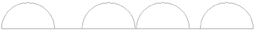
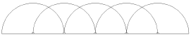
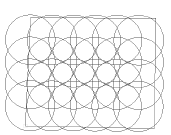
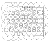
Design zones also analyze the spray/arc patterns and can help you estimate the coverage overlap of outlets, as well as determine whether some areas do not have sufficient coverage.
The following modes are available.

Mode |
Parameter |
|---|---|
Outlet Type list |
Select the type of outlet to be considered for the design zone; if there are multiple types, choose Select Multiple |
Polyline Creation Options |
Selects the method for drawing the polyline upon which the object is based; see Criando Polilinhas |
Preferences |
Sets the default preferences for the design zone object |
To create a design zone:
1 Before creating the design zone, place outlets and, optionally, a POC on the drawing, in the expected configuration.
2 Click the tool and select the Outlet Type from the Tool bar.
Choose Select Multiple if the design zone should consider various types of outlets. The Select Outlet Types dialog box opens; place a check mark in the Include column for outlets to be considered by the design zone. When the zone will contain multiple outlet types, <Multiple Selection> displays in the Outlet Type list.
3 Click the appropriate mode from the Tool bar to specify the creation method of the design zone polyline.
Alternatively, create a polyline and then select the Create Objects from Shapes command (see Creating Objects from Shapes).
4 Click to start drawing the design zone. As you draw the design zone polyline, outlets to be included in the design zone are highlighted. Draw the design zone polyline, clicking at each vertex. Click at the start point, or double-click, to finish drawing the design zone.

The Design Information section, available from the Object Info palette, provides analysis data to help determine whether the outlets in the design zone are efficiently using the water supplied by the POC. Change the outlet types considered by the design zone calculations by clicking Reassign Outlets.
After creation, the design zone shape can be edited with the Reshape tool. The design zone properties can be edited from the Object Info palette.
► Click to show/hide the parameters.
~~~~~~~~~~~~~~~~~~~~~~~~~
 Placing Pipes
Mode |
Tool |
Tool set |
|---|---|---|
Modes for the Ferramenta Polilinha |
Pipe
|
Irrigation |
The Pipe tool places main line, lateral line, and drip tubing irrigation pipes on the drawing. (The drip tubing transfers the water to drip emitters along its length; this is different from drip outlet tubing, which allows water to leak out.) The parameters for the irrigation pipes are based on standard pipe materials and diameter values from the catalog.
In Autoconnect mode, a pipe connects to existing outlets or other irrigation components as the pipe crosses over them while it is drawn. When Autoconnect mode is disabled, the end of the pipe needs to meet the other component to be connected. A pipe connected to another pipe splits the existing pipe in two. A pipe that is drawn over, but is not connected to, another pipe, displays with a “jump” arc to show that they do not intersect.
For a given flow rate, a smaller pipe results in a higher velocity. When pipes are placed with the Min Diameter Not Exceeding Velocity Limit option selected, the pipe’s size is adjusted automatically as needed to ensure a safe water velocity. The pipe size is set to the smallest pipe size (available from the Sizing List in the irrigation settings) that does not result in a velocity above the Maximum Velocity value from the irrigation settings. Both of these settings can be set independently for main lines and lateral pipes. After the pipe is placed, if any changes are made to the system that affect the calculated flow rate through the pipe, the pipe size adjusts to accommodate the flow.
The default pipe material specified in the irrigation settings is used for all the pipes unless a different material is selected with the Pipe option on the Tool bar.
The following modes are available:

Mode |
Description |
|---|---|
Main |
Creates a main line pipe |
Lateral |
Creates a lateral line pipe |
Drip Tubing |
Creates drip tubing |
Pipe |
Opens the Resource Selector to select a pipe resource for placement; double-click a resource to select it. Select from one of the pipe libraries, or select the drip default material or main default material for the pipe and set its properties after placement. |
Autoconnect |
With this mode enabled, when the pipe is drawn over existing, valid irrigation objects such as valves, outlets, and POCs, they are automatically connected to the pipe. Connecting the drawn pipe to an existing pipe splits the existing pipe. When this mode is disabled, the drawn pipe is not connected to objects unless the pipe’s endpoint touches the objects. |
Polyline Creation Options |
Selects the method for drawing the polyline upon which the object is based; see Criando Polilinhas |
Preferences |
Sets the default preferences for the pipe object |
To place a pipe on the drawing:
1 Click the Pipe tool and mode. Click Pipe from the Tool bar. From the Resource Selector, double-click a resource to activate it. Select from one of the pipe libraries, or select the drip default material or main default material and set its properties after placement.
Alternatively, create a polyline and then select the Create Objects from Shapes command (see Creating Objects from Shapes).
2 Click Preferences.
The Object Properties dialog box opens. Select the default pipe settings. The Pipe tool uses these preferences until they are changed again.
► Click to show/hide the parameters.
3 Click to place the start of the pipe, and draw the pipe polyline, clicking at each vertex. Double-click to finish drawing the pipe.

If Autoconnect mode is on, the pipe connects any valid irrigation objects that it crosses. When one end of the pipe is placed on another pipe, they are connected, and the existing pipe is split into two pipes.
Deleting the pipe later does not automatically reconnect the existing pipes.
A pipe drawn over another pipe displays with a jump at the intersection of the two pipes. Adjust the jump radius with the control point; hide or show the jump with the Hide Jump or Show Jump drop-down context menu command.

The pipe properties can be edited from the Object Info palette.
► Click to show/hide the parameters.
~~~~~~~~~~~~~~~~~~~~~~~~~
 Placing Valves
Tool |
Tool set |
|---|---|
Valve
|
Irrigation |
The Valve tool places an irrigation valve with parameters from a selected manufacturer or a custom valve with parameters that can be specified after placement. Various valves provide a wide array of functions in an irrigation system. Depending on the type of valve, different parameters are available.
• Control or zone valves connect the system’s main line to the associated lateral lines and downstream outlets.
• Master valves connect the entire irrigation system to the water source near the point of connection.
• Zone kit valves consist of valve, filter, and regulator in preassembled kits.
A valve added to a pipe splits the existing pipe in two.
To place valves on the drawing:
1 Click the tool and then click Valve from the Tool bar. From the Resource Selector, double-click a resource to activate it. Select from one of the manufacturer libraries, or select the custom valve from Custom.vwx and set its properties after placement.
2 Click once to place the valve. If placing the valve over an existing pipe or irrigation pipe network, the connecting pipe is highlighted and the valve is automatically connected to the network.
Adjust the location of the valve labels by dragging the label control point.

The valve properties can be edited from the Object Info palette. Available parameters depend on the valve type.
► Click to show/hide the parameters.
~~~~~~~~~~~~~~~~~~~~~~~~~
 Placing Point
of Connection (POC) Objects
Placing Point
of Connection (POC) ObjectsTool |
Tool set |
|---|---|
Point of Connection
|
Irrigation |
The Point of Connection tool places a POC object, which represents the source of water for the irrigation system. Normally, there is only one POC for the system. There are two types of POC: service line and custom. A service line has a known and predictable static pressure value. Custom types of POC include pumps and cisterns or other types of water sources.
To place a POC on the drawing:
1 Click the tool, and then click Point of Connection on the Tool bar. From the Resource Selector, double-click a resource to activate it. Select from one of the point of connection libraries, or select a custom resource from Custom POCs.vwx and set its properties after placement.
2 Click Preferences.
The Object Properties dialog box opens. Select the default POC settings. The Point of Connection tool uses these preferences until they are changed again.
► Click to show/hide the parameters.
3 Click once to place the POC. If placing the POC over an existing pipe or irrigation pipe network, the connecting pipe is highlighted and the POC is automatically connected to the network.
Adjust the location of the POC labels by dragging the label control point.

The POC properties can be edited from the Object Info palette. Available parameters depend on the POC type.
► Click to show/hide the parameters.
~~~~~~~~~~~~~~~~~~~~~~~~~
 Placing
Irrigation Controllers
Placing
Irrigation ControllersTool |
Tool set |
|---|---|
Controller
|
Irrigation |
The Controller tool places an irrigation controller object, representing the electronic devices that are programmed to control valves. Controllers with parameters from a selected manufacturer are available, or a controller can be placed as a custom controller with parameters that can be specified after placement. Controllers do not connect to irrigation networks.
To place a controller on the drawing:
1 Click the tool, and then click Controller from the Tool bar. From the Resource Selector, double-click a resource to activate it. Select from one of the manufacturer libraries, or select the custom resource from Custom.vwx and set its properties after placement.
2 Click once to place the controller.

The controller properties can be edited from the Object Info palette.
► Click to show/hide the parameters.
~~~~~~~~~~~~~~~~~~~~~~~~~
 Placing
Irrigation System Components
Placing
Irrigation System ComponentsTool |
Tool set |
|---|---|
System Component
|
Irrigation |
A variety of additional objects may be needed to make the irrigation design complete. These electrical and mechanical devices can be added to the drawing with the System Component tool.
The predefined objects that can be placed include: auto-fill device, backflow preventer, blow out connection, environmental sensor/station, filter, flow sensor, hose bib/faucet, pressure regulator, quick coupler, valve box/enclosure, water meter, and other. You can also place a generic system component with parameters that can be specified after placement.
A system component added to a pipe splits the existing pipe in two.
To place a system component on the drawing:
1 Click the tool, and then click System Component from the Tool bar. From the Resource Selector, double-click a resource to activate it. Select from one of the manufacturer libraries, or select a custom resource from Generic.vwx and set its properties after placement.
2 Click Preferences.
The Object Properties dialog box opens. Select the default system component settings; in particular, specify the component type and symbol to use. The System Component tool uses these preferences until they are changed again.
► Click to show/hide the parameters.
3 Click once to place the system component. If placing the component over an existing pipe or irrigation pipe network, the connecting pipe is highlighted and the component is automatically connected to the network.
Adjust the location of the component labels by dragging the label control point.

The system component properties can be edited from the Object Info palette. Available parameters depend on the system component type.
► Click to show/hide the parameters.
~~~~~~~~~~~~~~~~~~~~~~~~~
 Sizing Pipes
Command |
Path |
|---|---|
Size Pipes |
Landmark > Irrigation |
The diameter of the pipes in the irrigation design, along with the size of the valves and system components, has a direct effect on the pressure and velocity of the water moving through the system, which, in turn, affects the performance of the outlets and the longevity of the pipes and other components. As pipes are placed in the design, they are automatically sized based on velocity, if the Min Diameter Not Exceeding Velocity Limit option is selected.
As a final fine-tuning operation that should take place once the system has been designed, the Size Pipes command calculates the optimal pipe diameter and, optionally, valve and system component size, for each section of pipe based on the pipes in the Sizing List in irrigation settings. The optimally-sized pipes, valves, and system components are determined for a sub-section of the network or for the entire network, depending on the current drawing selection and the options chosen in the Size Pipes dialog box.
The pipes are sized so that each does not exceed its velocity limit (Maximum Velocity, specified in the irrigation settings), each outlet receives sufficient pressure to meet its designed input pressure requirement, and the pressure difference between the first and last outlet in a lateral line is within the Max Outlet Pressure Variation from the irrigation settings. The valve sizes, if valves are selected for sizing, are adjusted to be the most appropriate for the system’s flow rate, based on availability within the catalog for the selected manufacturer and series. When selected for sizing, system components are sized to a version that is closest to the pipe size, if available.
When all pipes are selected for sizing, this command will likely change any previously set pipe diameters and, if selected, valve and system component sizes.
To size pipes, and optionally, valves and system components:
1 Determine the extent of the sizing and select the appropriate object.
• To size lateral pipes in a valve’s zone, select the valve, which must be connected to at least one outlet by lateral pipes.
• To size all the pipes in a system, select the POC.
• To size all the pipes in the drawing, do not select any objects.
2 Select the command.
The Size Pipes dialog box opens.
3 Specify whether the sizing should affect only pipes that have already been sized by the command, or all pipes. A pipe is considered unsized when the Min Diameter Not Exceeding Velocity Limit option in the Object Info palette is selected.
4 Select whether the valves and system components that are connected to the system should also be changed if needed.
5 If needed, click Settings to open the irrigation settings dialog box. View or modify the Pipe Sizing parameters on the Pipes/Tubing tab. Click OK to return to the Size Pipes dialog box.
6 Click OK to size the designated pipes, valves, and system components.
If there are no suitable pipes or valves that meet the requirements, an alert opens.
After the command has been executed, the Object Info parameter Min Diameter Not Exceeding Velocity Limit is automatically deselected for all sized pipes, because the pipes were already sized to the best Nominal Diameter value, within the velocity limits specified in the irrigation settings. There should be no warnings for problem parameters within the network.
~~~~~~~~~~~~~~~~~~~~~~~~~
 Adding Labels to Irrigation Objects
Tool |
Tool set |
|---|---|
Tag/Label
|
Irrigation |
The Tag/Label tool attaches standardized labels to any of the objects in the drawing. The labels can display any of the associated object parameters that you need to show, such as names, notes, values, text, and so on. Records attached to objects in the drawing, including custom records with specific parametric data, can be displayed within the tag/label. In addition, a record can be attached to the label itself, and its fields can be reported.
Label configurations (number of fields displayed, appearance, and the parameters displayed) are saved as part of the label symbol and are associated with the object type. This allows the same label symbol to be used for different irrigation objects. Any symbol can be used as a label symbol; see Editing Tag/Label Symbol Definitions
To label an object in the drawing:
1 Click the tool.
2 Do one of the following:
• To use an existing object from the resource libraries, click Tag/Label on the Tool bar. From the Resource Selector, double-click a resource to activate it. Select from one of the tag/label libraries, or select a custom resource from Generic.vwx and set its properties after placement. The default label symbols are categorized by irrigation object type, and should work well for displaying the parameters of those objects; all of the labels can be customized.
• To create a custom object, click Preferences. From the Object Properties dialog box, set the default properties. The properties can be edited from the Object Info palette.
3 As you move the cursor over a valid object, such as an irrigation object, the object is highlighted; click on the object to be labeled.
4 Move the cursor to define the leader line length, and click to place the shoulder point and the label.

Align and distribute the leader lines for improved readability with the Align/Distribute Leader Lines command (see Alinhando e Distribuindo Linhas de Indicação).
The label association point indicates which object is labeled; move the control point to associate the label with a different object. The label information updates automatically.
The label properties can be edited from the Object Info palette.
► Click to show/hide parameters.
~~~~~~~~~~~~~~~~~~~~~~~~~
 Configuring and Saving Tag/Labels
The default labels are associated with parameters that might typically be displayed for the various drawing objects. However, each label can be individually configured to display custom information. The custom label parameter configuration can then be saved in the drawing in the symbol definition; one symbol can be used to label different objects. The symbol definition can be edited to add labels, change the position of the labels, size of the text, and appearance, position, and size of the label design elements.
To configure and save a tag/label:
1 Select the tag/label object.
2 From the Object Info palette, click Edit Tag/Label.
The Tag/Label Edit dialog box opens.
► Click to show/hide the parameters.
3 Once you have set up the display for the selected tag/label symbol, click Save As Default to be able to reuse the symbol data assignment for other drawing objects. The tag/label is saved as a symbol definition and displays in the Resource Manager, where its layout can be edited if necessary, and it can be shared with other files.
The label information updates automatically.
~~~~~~~~~~~~~~~~~~~~~~~~~
 Editing Tag/Label Symbol Definitions
The tag/label objects selected for use in the drawing become 2D symbol definitions, available from the Tag/Label Symbols folder in the Resource Manager. Edit the 2D component of the symbol definition as described in Editando Definições de Símbolo. The symbol insertion point is also the shoulder point of the tag/label.

Possible edits:
• Use the Attributes palette to change the geometry or text color.
• Change the size of the text and/or the text box.
• Apply a text style to the labels.
• Remove or reposition the text or geometry.
• Add geometry or text fields to the label. New fields must consist of the field number with a # on either side. After the symbol definition has been edited, the new field will require a value type assignment in the Tag/Label Edit dialog box; save the assignment in the symbol definition by clicking Save as Default.
~~~~~~~~~~~~~~~~~~~~~~~~~
 Irrigation System Warnings
As irrigation components are added to the design, the Vectorworks Landmark software verifies their connection to the irrigation network, and checks the stated catalog requirements to see if the product specifications are being met. If not, an error is generated. A warning icon appears in the drawing for the selected components with an issue, and in the Object Info palette, red text indicates the nature of the problem.

To see warning icons for more than one selected object at a time, the Unrestricted Interactive Scaling mode of the Selection tool must be enabled.
The following warnings can be generated:
Warning |
Description |
|---|---|
Exceeds Max Catalog Flow |
The object’s flow rate, either from design or calculated information, exceeds the specified maximum flow rate |
Exceeds Max Catalog Pressure |
The object’s pressure, either from design or calculated information, exceeds the specified maximum pressure |
Exceeds Max Line Length at Pressure |
The drip line is too long for the supplied pressure |
Excessive Velocity |
The pipe’s velocity, either from design or calculated information, exceeds the maximum velocity specified in the irrigation settings |
Object Not Connected to Network |
The irrigation object needs to be connected to the network |
Object Not Expected on Lateral Line |
An inappropriate object, such as a valve, is present on the lateral line (excludes connecting valves) |
Object Not Expected on Main Line |
An inappropriate object, such as an outlet, is present on the main line |
Under Min Catalog Flow |
The object’s flow rate, either from design or calculated information, is below the specified minimum flow rate |
Under Min Catalog Pressure |
The object’s pressure, either from design or calculated information, is below the specified minimum pressure |
A system under development may have several warnings; if the warning icons become distracting, select Landmark > Irrigation > Hide Warning Icons. To display the icons again, select Landmark > Irrigation > Show Warning Icons.
To easily identify which irrigation system components have a warning, select Landmark > Irrigation > Select Components with Warnings.
~~~~~~~~~~~~~~~~~~~~~~~~~