Creating Plant
DefinitionsCreating Plant
Definitions
Creating Plant
DefinitionsCreating Plant
DefinitionsThe Plant tool both defines and places plant objects. The plant database maintains an extensive set of plant data that can be used in plant definitions.
Placing plants is extremely flexible. Place plants pre-defined with species information and appearance settings, or add generic plants to the drawing and re-assign them to a specific plant species later in the design process. A selected plant can be placed individually or in multiples. Once placed, a plant group can be changed into individual plants, or individual plants can be grouped. In addition, defined and undefined plant masses can be created according to several methods.
A plant definition includes the specific 2D and 3D plant appearance, parameters, and botanical data. Plants are defined by editing a current definition or by creating a duplicate of a current definition. The plant definition is specified by entering parameters or by loading (and editing) botanical data from the plant database.
When the Vectorworks Landmark product is installed, a generic plant objects library is included. In addition, 2D and 3D plant symbols are provided as default content (default content is automatically imported into the current file at the point of use and displays in the Resource Browser; see “Resource Libraries” on page 215). The resources in the Plant Defaults.vwx file are available in the Plant Settings dialog box.
When plants are defined, the definition parameters apply by default; individual plant settings can be changed before the plant is inserted on the drawing, in the Plant Settings dialog box, or after placement, in the Object Info palette.
Click here for a video tip about this topic (Internet access required).

To create a plant definition:
1. Click the Plant tool from the Site Planning tool set.
2. The Plant Settings dialog box opens automatically if plants have not yet been placed in the drawing. Otherwise, click Preferences from the Tool bar.
The Plant Settings dialog box opens.
3. On the Definition pane, select a plant symbol that is close in appearance to the new plant.
Plants can be placed with just this basic information; see “Adding Plants to the Design” on page 793. The plant definition can be edited later if desired.
4. Click Edit Definition from any pane in the Plant Settings dialog box to edit the current definition, or click Duplicate from the Definition pane to create a new plant definition based on the selected plant. Alternatively, to edit a plant definition, select a plant from the drawing, select Edit from the Resources menu or the plant context menu, and select Definition.
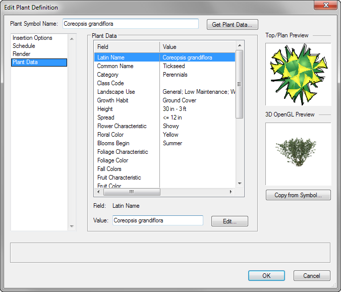
Whether creating a new plant from a duplicate, or editing a current plant definition, the Edit Plant Definition dialog box opens, displaying the selected plant symbol. Provide a name for the plant symbol, and then specify the plant parameters on each tab to define the plant. As the parameters are defined, the preview dynamically displays the plant appearance.
Although the Edit Plant Definition dialog box and the Plant Settings dialog box appear similar, keep in mind that the plant definition parameters define the default plant settings. The default plant settings can be changed at placement, allowing for variations of the same plant definition.
To automatically add plant information from the plant database, click Get Plant Data (see “Using Plant List Data in Vectorworks Landmark” on page 814).
The plant definition’s geometry can be based on a symbol present in the file or from default plant content, from drawing objects in the file, or from another plant; see “Creating Plant Geometry” on page 791.
5. When the default plant parameters have been defined, click OK to return to the Plant Settings dialog box. From there, additional plants can be defined, and a plant can be selected for placement.
When using workgroup referencing, the plant definitions must exist in the same file as the site model they reference, so that their Z values can be set to the site model surface.
Plant resources can be exported from the Resource Browser or by selecting Export Plant from the plant context menu; see “Exporting Custom Resources” on page 229.
Each pane of the plant definition dialog box is described in the following sections.
Every pane of the plant definition displays the Plant Symbol Name and previews, allows botanical data to be obtained from the plant database, and provides the option to obtain the 2D and 3D plant geometry from a symbol. The previews update as the plant definition changes.
Click to show/hide the parameters.
Specify the default insertion options for the plant definition on the Insertion Options pane.
If plant data were obtained from the plant database, the plant database values are displayed. Values and settings entered on this tab become the default for the plant definition. These default values can be changed for individual plants.
Click to show/hide the parameters.
Click the Schedule pane to specify default plant values for display and reporting.
If plant data were obtained from the plant database, the plant database values are displayed. Values and settings entered on this tab become the default for the plant definition. These default values can be changed for individual plants.
Click to show/hide the parameters.
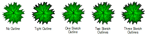
Click the Render pane to specify the 2D plant styles. These effects display in Top/Plan view only; plant shadows do not display in worksheet images. A document preference makes it easy to give plans a uniform appearance by applying a document-wide shadow style to all plants and massing models in a drawing (see “Preferências das Sombras do Plano” on page 60). Even when a document preference is set, plant definitions can be edited on the Render pane to customize the drawing’s appearance. The outline, massing, and shadow parameters can be toggled for all plants in a document by selecting View > Show > Show or Hide Plant Styles.
Values and settings entered on this tab become the default for the plant definition. These default values can be changed for individual plants.
Click to show/hide the parameters.
Click the Plant Data pane to view the plant database information for the plant.
To add botanical data from a plant list to the plant definition, click Get Plant Data and select a plant (see “Using Plant List Data in Vectorworks Landmark” on page 814).
To change the plant data for the current plant definition only (without changing the plant list data), click on the parameter and click Edit. Enter the new value in the Edit Field dialog box and click OK.
~~~~~~~~~~~~~~~~~~~~~~~~~
 Creating
Plant Geometry
Creating
Plant GeometryThe plant geometry in a plant definition can easily be created from another symbol, from drawing objects, or from another plant.
To create plant geometry from another symbol:
1. Begin to create a plant definition as described in “Creating Plant Definitions” on page 787.
2. From the Edit Plant Definition dialog box, click Copy from Symbol.
The Copy From Symbol dialog box opens. From the symbol list, select the symbol that has the geometry to copy and choose whether to copy the 2D, 3D, or both components of the symbol geometry.
Click to show/hide the parameters.
3. Click OK to copy the selected geometry from the symbol to the current plant definition.
To create plant geometry from drawing objects:
1. Select the 2D, and optionally, 3D drawing objects to use in a new plant definition.
A plant symbol can be created from another symbol. The xFrog plant images can be used as a basis for the 2D geometry.
2. Select the Create New Plant command from the appropriate menu:
• Designer: AEC > Plants > Create New Plant
• Landmark: Landmark > Create New Plant
Alternatively, right-click (Windows) or Ctrl-click (Mac) in the drawing, with the geometry or plant symbol selected, and select Create New Plant from the document context menu.
The Edit Plant Definition dialog box opens, with the plant symbol name as “Untitled Plant.”
3. Specify the plant definition parameters, similar to creating a new definition (see “Creating Plant Definitions” on page 787).
4. Click OK to create the new plant.
If no 3D geometry was originally included, the plant symbol contains a 3D locus by default. Once the plant has been created, edit the 3D component of the plant symbol to add the 3D geometry. See “Editing Symbol Definitions” on page 243 for information on editing symbol components. Image props, such as those provided by xFrog, can be used as 3D plant geometry.
To create plant geometry from an existing plant:
1. Select the existing plant with geometry to convert to a new plant symbol.
2. Select the Create New Plant command from the appropriate menu:
• Designer: AEC > Plants > Create New Plant
• Landmark: Landmark > Create New Plant
Alternatively, select Create Plant from Object from the plant context menu, or select the plant to duplicate from the Resource Browser, and select Resources > Duplicate, and then Resources > Edit.
The Edit Plant Definition dialog box opens, with the plant name symbol as “Untitled Plant.”
3. The plant graphics and parameters are based on the original plant. Specify new plant definition parameters, similar to creating a new definition (see “Creating Plant Definitions” on page 787).
4. Click OK to create the new plant.
 Adding
Plants to the Design
Adding
Plants to the DesignPlant placement in the Vectorworks Landmark program is very flexible. Generally, plants are defined first, and then placed; plant parameters are set by the definition, but if necessary, certain parameters can be changed in the Plant Settings dialog box before placement, or in the Object Info palette after placement. This allows variations of the same plant definition, which is an essential part of a landscape designer’s workflow. Another way of placing plants is to place “generic” plants from the default content, and create plant definitions for them later.
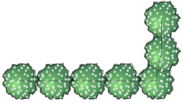
In addition to the appearance and parameters defined for plants, the Plant tool can place plants in several configurations, from single plants to arrays of plants. When setting parameters after placement, an array of plants is considered to be a single “plant” in the Object Info palette. Plants can also created by drawing a polyline and then selecting the Create Objects from Shapes command (see “Creating Objects from Shapes” on page 273).
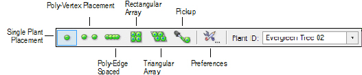
Mode |
Description |
|---|---|
Single Plant Placement |
Places a single specified plant at each mouse click
|
Poly-Vertex Placement |
Places plants at each clicked polygon vertex
|
Poly-Edge Spaced |
Places plants along the drawn polygon at the Spacing distance specified in the definition or settings
|
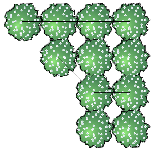
Rectangular Array |
Fills the drawn polygon with plants in a rectangular array at the Spacing distance specified in the definition or settings
|
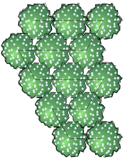
Triangular Array |
Fills the drawn polygon with plants in a triangular array at the Spacing distance specified in the definition or settings
|
Pickup |
Sets the default plant settings to match those of a selected existing plant |
Preferences |
Opens the Plant Settings dialog box, for specifying the plant to place, its placement options, and its definition |
Plant ID |
Selects a plant for placement by its ID (Plant Symbol Name) |

To place plants on the drawing:
1. Click the Plant tool from the Site Planning tool set and select the plant to place.
The Plant Settings dialog box opens automatically if there are no plants in the Resource Browser. Otherwise, click Preferences from the Tool bar to select the plant to place, and specify the plant settings if they are different from the definition. The plant settings are described in the following sections.
The plant to place can also be selected by its plant symbol name from the Plant ID list on the Tool bar. The plant resources in the active drawing display alphabetically at the top of the list; the remaining plants are from the default content resources.
Double-click a plant from the Resource Browser to activate the Plant tool and place the selected plant.
The Plant tool uses these settings until they are changed again by selecting a different plant ID from the Tool bar, clicking Preferences from the Tool bar, or until Pickup mode is selected, which changes the default settings to those of a selected existing plant.
2. Select the plant placement mode from the Tool bar.
3. Depending on the placement method selected, either click in the drawing to place a single plant, or draw a polygon. As the Plant tool is clicked in the drawing, a preview of the plant spread is displayed to help with plant placement.
The Plant tool parameters are retained so that the successive placement of plants is easily accomplished.
Each pane of the plant settings is described in the following sections. As the parameters are defined, the preview dynamically displays the plant appearance.
Do not be confused by the similar appearance of the Plant Settings dialog box and the Edit Plant Definition dialog box; keep in mind that the plant definition parameters define the default plant settings. The default plant settings can be changed at placement if needed, allowing for variations of the same plant definition. Default plant settings that do not require editing can be left as defined by the plant definition.
The Definition pane can be used to select the plant definition for placement by the Plant tool. From any pane, you can also edit the plant definition parameters or create a duplicate of the plant definition, as described in “Creating Plant Definitions” on page 787.
Click to show/hide the parameters.
The Insertion Options pane displays the default plant insertion settings from the plant definition. To override the plant definition parameters, select the parameter check box and enter the custom value. In addition, if the plant should be included in plant report worksheets, select On Plant List.
Click to show/hide the parameters.
Select plant display parameters on the Annotation pane.
Click to show/hide the parameters.
The Render pane displays the default render settings from the plant definition. The Use Plant Definition settings indicate that the plant definition render settings apply; see “Plant Definition: Render Pane” on page 789. To override the plant definition parameters, select the Custom outline and massing option, and/or select the No Shadow, Use Document Preference Settings, or Custom shadow setting.
Set the display of the plant ID tags on the Tag pane. To create a custom plant tag, see “Creating a Custom Plant Tag” on page 798. After creation, the plant tag’s appearance can be modified via the Plant Settings Tag pane, Object Info palette, tag class settings, and the control point locations on the drawing (see “Plant Tag Appearance” on page 800).
Click to show/hide the parameters.
The Schedule pane displays the default schedule settings from the plant definition; see “Plant Definition: Schedule Pane” on page 789. To override the plant definition parameters, select the parameter check box and enter the custom value.
~~~~~~~~~~~~~~~~~~~~~~~~~
 Creating
a Custom Plant Tag
Creating
a Custom Plant TagIn addition to providing several predefined plant tags, Vectorworks Landmark allows designers to create custom plant tags.
1. From the Tag pane of the Plant Settings dialog box, select Set Custom Tag from one of the Top / Center / Bottom fields. Settings for the plant tag currently displaying in this field are displayed in the Set Custom Tag dialog box.
The Set Custom Tag dialog box opens.
If editing an existing tag through the Object Info palette, the selected tag’s data displays.
2. Select values from predefined plant record fields in the order they should be listed, and type the delimiter text to place between the fields. Select <New Line> to start the next tag item on a new line. Up to six different combinations of fields, delimiters, and new line separators can be used. Entering a custom tag in the Top field of the Plant Settings dialog box will insert the custom tag above the reference line, a custom tag in the Center field will replace the reference line, entering a custom tag in the Bottom field will appear below the reference line.
The Tag Appearance field displays a static text preview of the custom tag. To preview a tag in its entirety, click-drag the bottom right corner of the dialog box to resize it.
3. Click OK.
4. Repeat steps 1 through 3 for the other Top / Center / Bottom fields on the Plant Settings dialog box, as appropriate, to complete creation of the custom tag.
~~~~~~~~~~~~~~~~~~~~~~~~~
 Plant
ID Codes
Plant
ID CodesThe meaning of commonly-used plant ID code categories is provided.
Plant ID Code |
Meaning |
|---|---|
A-# |
Annual # |
CTD |
Conifer Tree Display |
CTG |
Conifer Tree Generic |
ETD |
Evergreen Tree Display |
ETG |
Evergreen Tree Generic |
G-# |
Grasses # |
OT-M |
Ornamental Tree Massed |
OTD |
Ornamental Tree Display |
OTF |
Ornamental Tree Flowering |
OTG |
Ornamental Tree Generic |
OTM |
Ornamental Tree Multi-Stem |
OTP |
Ornamental Tree Patio |
P-1 — P-9 |
Perennials |
P1 — P4 |
Palms |
SD-# |
Shrub Display # |
SD# |
Shrub Deciduous # |
SDM |
Shrub Display Massed |
SG# |
Shrub Evergreen # |
SG |
Shrub Generic |
SN# |
Shrub Needle # |
STG |
Shade Tree Generic |
STL |
Shade Tree Large |
STM |
Shade Tree Massed |
STP |
Shade Tree Patio |
STS |
Shade Tree Street |
 Editing Plants
The plant properties are displayed, and can be edited, in the Object Info palette. As plants are placed, they take on the properties of the associated plant definition and/or the properties in the Plant Settings dialog box. Changes made in the Object Info palette for the selected plants apply to those individual plants only; changes are not reflected in the plant definition.
For multi-plant placement options, edit the polygon defining the plant with the Reshape tool if necessary; the plant placement automatically adjusts to fit the new shape.
Click to show/hide the parameters.
~~~~~~~~~~~~~~~~~~~~~~~~~
 Plant
Tag Appearance
Plant
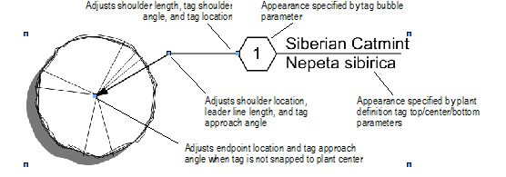
Tag AppearancePlant tag appearance and placement is flexible, and can be adjusted in several ways, including through the plant settings, Object Info palette, tag class settings, and the control point locations on the drawing.
• Individual plant tags can then be changed for selected plants by adjusting the plant tag parameters in the Object Info palette. For example, selected plants in one area of a planting plan look more uniform when they all use the same tag approach and tag shoulder angle.
• The plant tag class controls the appearance of the leader/shoulder lines, as well as the marker style.
• To move the plant tags of several selected plants at once, click the Unrestricted Interactive Scaling mode of the Selection tool.
• To align plant tags for improved readability, use the Align/Distribute Leader Lines command (see “Aligning and Distributing Leader Lines” on page 1033).
• If an individual tag needs to be repositioned, plant tags also have several control points for adjusting the tag text and leader line and shoulder position and angle.
~~~~~~~~~~~~~~~~~~~~~~~~~
 Editing Plant
Attributes
Editing Plant
AttributesPlants are hybrid symbols, containing a 2D symbol, and optionally, a 3D symbol. As plant definitions are created, the plant symbol is automatically imported into the current file and appears in the Resource Browser. Plants are “red” plug-in object symbols (see “Symbol Types” on page 233 for information on symbol types). The 2D and 3D plant graphics are scaled by the plant definition height and spread parameters.
Because plants are red symbols, plant attributes cannot be directly set or modified from the Attributes palette. Instead, edit the plant symbol components.
To edit plant symbol attributes:
1. Select the plant symbol in the Resource Browser. Select Resources > Edit, or select Edit from the Resource Browser context menu.
Alternatively, select a plant in the drawing window, and double-click or select Edit from the context menu.
The Edit Plant dialog box opens.
Click to show/hide the parameters.
2. Edits to the 2D or 3D components immediately affect all instances of the symbol. Changes to the plant definition affect all future instances of the plant.
 Replacing
Plants
Replacing
PlantsWhen replacing plants, select whether to replace the current plant only, or all instances of the selected plant.
To replace plants:
1. Select the plant(s) to replace, or select a plant that is a representative of the plant instances to replace.
2. From the Object Info palette, click Replace Plant.
Alternatively, Right-click (Windows) or Ctrl-click (Mac) on the plant and select Replace Plant from the context menu.
The Replace Plant dialog box opens.
Click to show/hide the parameters.
3. Click OK to replace the plant(s) or all the plant instances with the new plant.
~~~~~~~~~~~~~~~~~~~~~~~~~
 Modifying
Plant Clusters
Modifying
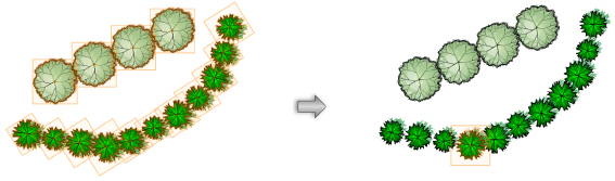
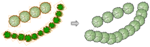
Plant ClustersPlants placed in a multiple placement mode of the Plant tool are associated as a cluster. The cluster moves together, and parameter changes affect all plants in the cluster. However, it is possible to dissociate the cluster to make individual plant changes. In addition, new clusters can be created with different combinations of plants. Clustering identical plants which are in close proximity can be desirable for labeling and identification purposes.
One or more plant clusters can be disassociated to change individual plant parameters or location.
To convert a plant cluster to individual plants:
1. Select the plant cluster or clusters to convert.
2. Select the Change Plant Grouping command from the appropriate menu:
• Designer: AEC > Plants > Change Plant Grouping
• Landmark: Landmark > Change Plant Grouping
Alternatively, right-click (Windows) or Ctrl-click (Mac) on the plant cluster and select Change Plant Grouping from the context menu.
3. If one plant cluster is selected, the plants in the cluster are automatically converted to individual plants.
4. If more than one plant cluster is selected, the Choose Mode dialog box opens.
5. Select Convert Selection into Individual Plants.
6. Click OK. The plants are converted, retaining their original plant type; they can be moved and changed individually.
Individual plants and plant clusters can be combined into a single plant cluster. The converted cluster will be a multi-plant placement at polygon corners.
To convert plants to a plant cluster:
1. Select the individual plants, plant clusters, or combination of individual plants and clusters to convert.
2. Select the Change Plant Grouping command from the appropriate menu:
• Designer: AEC > Plants > Change Plant Grouping
• Landmark: Landmark > Change Plant Grouping
Alternatively, right-click (Windows) or Ctrl-click (Mac) on the plant and select Change Plant Grouping from the context menu.
3. If the selection consists of individual plants of the same type, they are automatically converted to a single plant cluster.
4. If individual and clustered plants are selected, the Choose Mode dialog box opens.
5. Select Combine Plants into One Single Plant.
6. Individual and clustered plants of the same type are automatically converted to a single plant cluster.
If the selection consists of more than one plant type, the Please Choose Plant dialog box opens.
7. All the plants in the selection will be converted to one of the plant types. Select the plant type from the list and its Plant Spread value is displayed. Click OK.
8. The selected plants are converted to a single cluster of identical plant types.
Plants are clustered based on their drawing order. If the joining polygon of the resulting plant is not as expected, change the drawing order of the plants prior to joining them.
~~~~~~~~~~~~~~~~~~~~~~~~~
 The
Plant Database
The
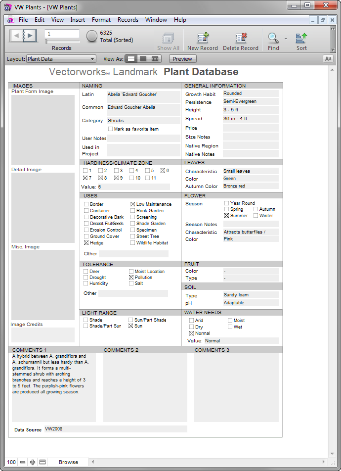
Plant DatabaseThe plant database provided with the Vectorworks Landmark product manages an extensive list of plant names and botanical information which can be used to associate specific plant data with plant definitions.
The plant database is a stand-alone FileMaker® application that opens in a separate window. The benefits of using the FileMaker database for plant data management include improved navigation, editing, searching, and filtering, as well as the ability to import data from industry-standard sources. At installation, a large set of plant records is provided.
FileMaker is a comprehensive data-management program. The details of every menu command and option are beyond the scope of this manual. However, all relevant information for using FileMaker in conjunction with the Vectorworks Landmark product is presented. Familiarity with FileMaker is not required to use the database or to manage botanical data, and to use that data in the Vectorworks program. The full version of FileMaker can also be used when working with the plant database. For in-depth information about FileMaker, including product documentation, visit www.filemaker.com and navigate to the Support area. (The plant database may not contain all the functionality documented for the full version of FileMaker.)
The general workflow consists of managing the botanical information in the plant database application, and from there, creating the plant lists to be used in the Vectorworks Landmark product.
~~~~~~~~~~~~~~~~~~~~~~~~~
 Accessing
the Plant Database
Accessing
the Plant DatabaseAccessing the plant database for the first time requires initial setup.
To access the plant database for the first time:
1. Select the VW Plants Database command from the appropriate menu:
• Designer: AEC > Plants > VW Plants Database
• Landmark: Landmark > VW Plants Database
Alternatively, right-click (Windows) or Ctrl-click (Mac) in the drawing and select VW Plants Database from the context menu.
The Choose Plant Database Location dialog box opens.
2. Indicate where the plant database information is to be located. By default, the plant database is stored locally, in the user folder of the computer where the Vectorworks software is installed. Larger offices that wish to share the plant database among several computers can store and access the plant database from a workgroup folder located on a central computer or server. Alternatively, select Browse for database folder and then click Browse to specify the desired location.
If this is the first time the plant database is being accessed and it does not yet exist in the specified location, the database is automatically created in that location. Whenever the plant database is opened in the future, it will use the data from that location. The location can be changed at any point by selecting the Choose VW Plants command from the appropriate menu:
• Designer: AEC > Plants > Choose VW Plants
• Landmark: Landmark > Choose VW Plants
It is possible to maintain several plant databases and switch among them with this command.
3. Click OK. The creation of a new plant database location may take a few moments.
The VW Plants dialog box may open. Specify a user name for the FileMaker application.
4. Click OK.
The Vectorworks Landmark plant database opens, in a separate window.
Once the plant database has been set up, it is accessed immediately when selecting Landmark > VW Plants Database. The plant database can also be accessed when creating a plant definition, by clicking Open VW Plants from the Get Plant Data dialog box.
~~~~~~~~~~~~~~~~~~~~~~~~~
 Importing
Plant Database Information
Importing
Plant Database InformationA default set of plant database records is provided at installation. The plant database supports several data formats for import, including tab-delimited files, Excel® spreadsheets, .xml files, and many others. The import folder feature allows movies and images to be imported. In addition, plant lists from previous versions of the Vectorworks program can be imported.
To import plant database information:
1. Open the plant database as described in “Accessing the Plant Database” on page 804.
2. Select the File > Import Records database command. Files, folders, or .xml files can be imported. Select this command to import plant lists from Vectorworks program versions prior to 12.
To import plant data from Vectorworks versions 2008 through 2012, first select the File > Convert VW Plants database command to convert the plant data to the most recent FileMaker format. Then, import the data with Import Records.
To import plant lists from Vectorworks 12.x, select the File > Import Vectorworks 12 Plant List database command.
3. After specifying the location of the file(s) to import, field mapping is required to import the data correctly into the current database. (For Vectorworks 12.x plant lists, field mapping is automatically performed.)
The important mapping fields for proper use in the Vectorworks Landmark product are described in “Plant Database Field Mapping” on page 816. If more information is required, consult the Support area of www.filemaker.com.
Click here for a video tip about this topic (Internet access required).
Additional plant datasets may be located in the Plant Database\VW Plants\Additional Datasets folder. These files typically contain regional plant sets provided by a distributor or other plant sets installed with the Vectorworks Landmark software. The field matching has already been performed for these data sets, and they are easy to add to the plant database.
To add plant data from the Additional Datasets folder:
1. Open the plant database as described in “Accessing the Plant Database” on page 804.
2. Select the File > Add Additional Plant Data database command.
Select the file to import. Field mapping is automatic, and the plant information is added to the plant database.
~~~~~~~~~~~~~~~~~~~~~~~~~
 Viewing
Plant Database Records
Viewing
Plant Database RecordsEach plant entry and its associated botanical information is considered a “record” in FileMaker. Several view modes display the records in ways designed to facilitate performing related tasks. When the plant database first opens, the records operate in Browse mode, with Forms displayed.
To familiarize yourself with the different display modes, and view the plant records in a variety of ways:
1. Open the plant database as described in “Accessing the Plant Database” on page 804.
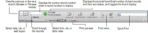
2. Select the View > Status Toolbar database command to enable viewing controls and status at the top of the record form. Many of these items can also be found on the View and Records menu.
3. From the Status toolbar and the View menu, select the view mode and layout options depending on the task to accomplish.
Mode or View Option |
Description |
|---|---|
View Mode |
|
Browse |
Displays plant record information and allows editing |
Find |
Displays a blank form for specifying search criteria |
Preview |
Displays plant record information as it will be printed |
View as Form |
Displays each record as an individual form or “page” |
View as List |
Displays records consecutively in a scrollable list |
View as Table |
Displays each record as an item in a table, for sorting and reordering |
Layout |
|
Data View |
Displays plant record information |
List View |
Displays limited plant data for each plant, for sorting and reordering |
Web View |
Displays a special browser (using the default system browser) for locating plant images and information |
Records Found toggle and status
|
After a search, the green toggle button displays an approximate pie chart and the number of records found; click the green pie chart button to toggle the display to records that are not in the found set. The sort status is also indicated. |
Show All |
Clears the results from a search, displaying all records |
New Record |
Adds a plant record to the database |
Delete Record |
Deletes the currently selected record from the database |
Find |
Switches to Find mode layout, for searching |
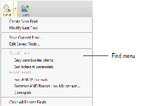
Find menu |
Allows searches to be saved, modified, recalled, and cleared |
Sort |
Opens the Sort Records dialog box, for determining the sort order for the plant records, or for unsorting the records |
Quick Find |
Searches for the text entered or recent searches, without switching to Find mode |
Preview |
Displays the records in a Print Preview mode |
~~~~~~~~~~~~~~~~~~~~~~~~~
 Searching
for Plants
Searching
for PlantsThe plant database can be searched from Quick Find in the Status toolbar or by switching the view to Find mode. Quickly search by entering text or repeating a recent search, or conduct flexible, sophisticated searches by combining search criteria. Search criteria can be saved and managed, making it easy to re-create plant lists.
Quick find searches the plant records for text.
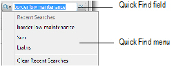
To perform a quick find search:
1. Type one or more search terms into the Quick Find field in the Status toolbar.
2. Press Enter.
3. The records that contain the search terms are displayed.
To quickly repeat a previous search, click on the Quick Find menu and select the search term used previously.
Find mode performs a more advanced search based on specific criteria. Searches can be saved and managed.
To search for plants in Find mode and manage found sets:
1. Open the plant database as described in “Accessing the Plant Database” on page 804.
2. Select the View > Find Mode database command or click Find from the Status toolbar. Alternatively, select Find > Create New Find.
A blank form opens and the display switches to Find mode. Find mode functions are available from the Status toolbar.
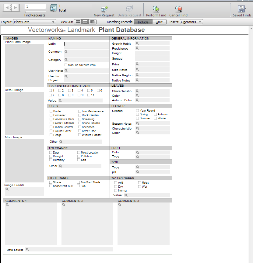
3. Enter the criteria for searching.
Examples include searching for the Latin name “Liatris,” Light Range “Sun,” with a Height > 3-5 ft.
Click the Omit button in the Status toolbar (or select the Omit options from the Records menu) to exclude, rather than search for, the criteria. Use the Operators list for even more specific searches.
4. Click Perform Find from the Status toolbar, or press Enter.
5. The view mode automatically switches to Browse, and the records that meet the search criteria are displayed.
6. To save the current set of search criteria, select Find > Save Current Find.
Other search criteria set maintenance can be performed from the Find menu, to modify, edit, clear, and select saved searches. A previously saved search is executed by selecting its name from the Find menu.
To return to viewing all the plant records, select the Records > Show All Records database command or click Show All from the Status toolbar.
~~~~~~~~~~~~~~~~~~~~~~~~~
 Managing
Plant Database Records
Managing
Plant Database RecordsPlant database records can be edited in Browse mode, whether in form, list, or table view (see “Viewing Plant Database Records” on page 806).
To edit plant records:
1. Open the plant database as described in “Accessing the Plant Database” on page 804.
2. Select the View > Browse Mode database command.
3. Select the plant record to edit by scrolling or searching.
4. Changes made to the fields and check boxes are automatically saved.
Useful edits include:
• Marking a plant as a Favorite (to search for favorite plants later)
• Indicating the Project Information (to track plants by project)
• Adding custom information to drop-down lists
• Placing an image, video, audio, pasted text, or link to an embedded object into one of three containers; right-click on an image container to access the options
• Adding image credits and data source information to avoid copyright issues
• Adding extra plant or project information that is useful in the Vectorworks program
Switch between metric and imperial units for the Height and Spread fields with the Edit > Options > Use Imperial Value Lists or Use Metric Value Lists database commands.
Project ID numbers and favorites can be easily be added to all plants found by a search, with the Records > Add Project ID and Records > Mark As Favorite database commands. These fields export to the Vectorworks program and are useful for tracking and finding plants. If the Project ID is no longer needed at the completion of a project, search for all plants with that ID and then select the Records > Delete Project ID database command to remove it.
To add a plant to the plant database list:
1. Open the plant database as described in “Accessing the Plant Database” on page 804.
2. Select the View > Browse Mode database command.
3. Select the Records > New Record database command or click New Record from the Status toolbar.
New records are appended to the end of the record set.
4. Enter the plant information. Information is saved automatically.
To remove a plant from the plant database list:
1. Open the plant database as described in “Accessing the Plant Database” on page 804.
2. Locate the record or records to delete, by searching or scrolling.
3. Select the Records > Delete Record database command or click Delete Record from the Status toolbar to delete an individual record, or Records > Delete Found Records to delete a found set of records.
Confirm the deletion; this action cannot be undone.
~~~~~~~~~~~~~~~~~~~~~~~~~
 Accessing
Plant Information from the Internet
Accessing
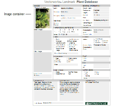
Plant Information from the InternetIf access to the Internet is available, plant images and information are easily obtained from within the plant database window. Images can be copied directly into the database (image credits can also be specified).
To access plant information from the Internet:
1. Open the plant database as described in “Accessing the Plant Database” on page 804.
2. Locate the plant record that requires images or information.
3. Select the View > Swap Data View/Web View database command to toggle to web view, or select the Web Data layout from the Status toolbar.
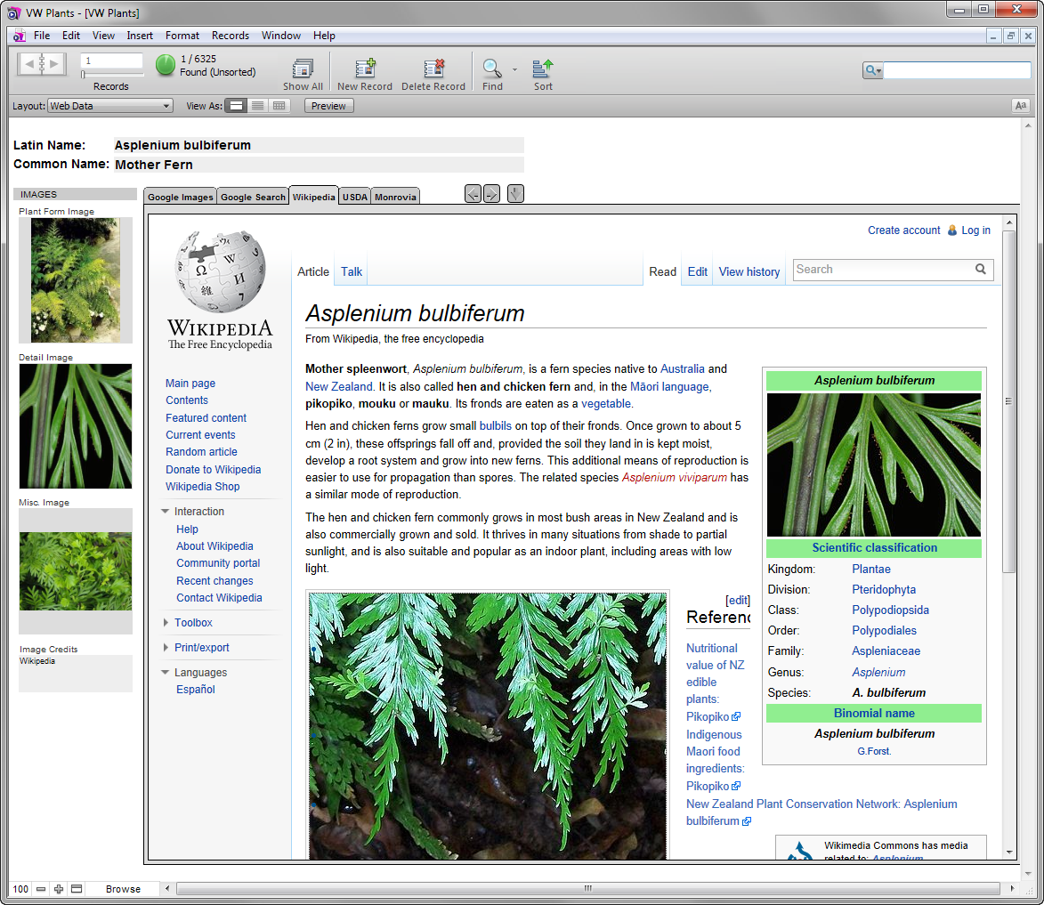
In web view, a search is automatically conducted for the current plant based on its Latin name, and information about it, as well as images, are displayed from different sources.
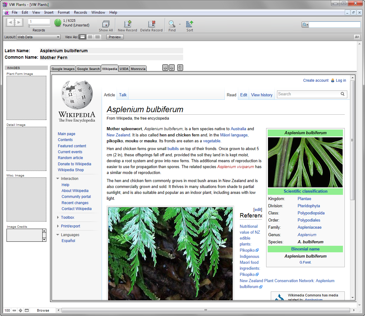
4. Click on the web view tabs to find plant information from the various sources. The available sources may depend on regional settings provided by a distributor.
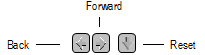
5. Click the buttons to navigate through the web pages of each tab or to reset the view to the initial search (based on the Latin name).
6. To easily copy an image from the Internet to the plant database, select Copy (Windows) or Copy Image (Mac) from the image context menu. Then select Paste from the image container context menu. Image credits can be added in the Image Credits area under the images, to avoid copyright issues.
Image files can also be saved and inserted into the database later, as described in “Editing Plant Records” on page 810.
7. Select the View > Swap Data View/Web View database command, or change the layout from the Status toolbar, to return to the database view.
~~~~~~~~~~~~~~~~~~~~~~~~~
 Creating
Plant Lists for Vectorworks Landmark
Creating
Plant Lists for Vectorworks LandmarkPlant lists are the connection between the FileMaker plant database and the Vectorworks Landmark product. Creating plant lists from the entire set, or from found sets, in the plant database allows that data to be attached to plants in the Vectorworks program. Create as many plant lists as necessary; the appropriate plant list is selected for the plant definition. The data attached to a plant becomes part of the plant definition, and can be added to planting plans and displayed by plant ID tags.
Plant lists are created from the plant database; plant lists can also be created automatically based on plant category.
To create a plant list from the plant database:
1. Open the plant database as described in “Accessing the Plant Database” on page 804.
2. Search for the plants to include in the plant list (see “Searching for Plants” on page 807). The plant list is created from a found set of records, or from all the plant records. Larger plant lists take longer to load into the Vectorworks program.
3. Select the File > Create Vectorworks Plant List database command.
The Create Plant List dialog box opens. Provide a name for the plant list.
4. Click OK.
The plant list file is a tab-delimited file saved in the location of the plant database.
Click here for a video tip about this topic (Internet access required).
To create plant lists based on plant category:
1. Open the plant database as described in “Accessing the Plant Database” on page 804.
2. Select the File > Create Category Plant Lists database command.
A plant list is created for each category. If there are no plants found for a category, no list is created for that category. Plants without a category assigned, or with a custom category, are not included. In addition, an “All” plant list contains all plants regardless of category.
3. The plant lists are tab-delimited files saved in the location of the plant database.
By default, all plants in the tree Category of the database are included in the Species Data dialog box for access by the Existing Tree tool. If desired, search the plant database for the trees you require, and then add only these trees to the existing tree species list.
To create a custom existing tree species list:
1. Open the plant database as described in “Accessing the Plant Database” on page 804.
2. Search for the trees to include in the existing tree species list (see “Searching for Plants” on page 807).
3. Select the File > Create ‘Existing Tree’ List database command. This customizes the existing tree list to use only the plants found in the database search.
~~~~~~~~~~~~~~~~~~~~~~~~~
 Using
Plant List Data in Vectorworks Landmark
Using
Plant List Data in Vectorworks LandmarkPlant list information is available to plant definitions from the Plant Data tab.
To use plant list data in a plant definition:
1. Create the plant definition as described in “Creating Plant Definitions” on page 787.
2. In the Edit Plant Definition dialog box, click Get Plant Data.
The Get Plant Data dialog box opens.
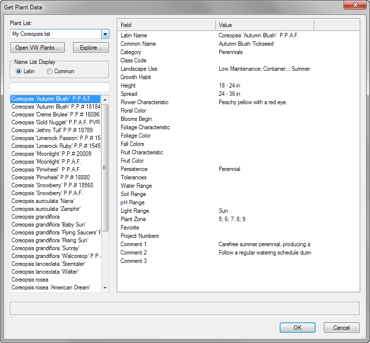
Click to show/hide the parameters.
3. Select the plant name and data to include in the plant definition, and click OK.
4. The Plant Data tab displays the data from the plant database.
~~~~~~~~~~~~~~~~~~~~~~~~~
 Plant
Database Field Mapping
Plant
Database Field MappingWhen plant data is imported into the Plant Database with the File > Import Records > File database command, field mapping is required (see “Importing Plant Database Information” on page 805). Certain fields must be used during mapping for the plant list to function properly when exported for use with the Vectorworks Landmark product. All significant Vectorworks fields have a VW prefix.
Target Field Name |
Notes or Example Values |
Target Field Name |
Notes or Example Values |
|---|---|---|---|
VW Autumn Color |
|
VW Height |
|
VW Bloom Time |
Also referred to as Season |
VW Landscape Use |
Border, Hedge, Shade Tree... |
VW Category |
Shrubs, Herbs, Trees... |
VW Latin Name |
Also known as the plant botanical name |
VW Climate Zone |
Arid, Semi Arid, Dry... |
VW Light Range |
Deep Shade, Shade, Sun, Full Sun |
VW Code |
|
VW Other Tolerance |
|
VW Comments 1 |
|
VW Other Use |
|
VW Comments 2 |
|
VW Persistence |
Deciduous, Semi-Evergreen, Evergreen... |
VW Comments 3 |
|
VW pH Range |
Acidic, Adaptable |
VW Common Name |
|
VW Price |
|
VW Favorites |
|
VW Region |
|
VW Flower Characteristics |
Double, Erect, Fragrant, Horizontal... |
VW Region Notes |
|
VW Flower Color |
|
VW Season Notes |
|
VW Foliage Characteristics |
Aromatic, Broad-leaf, Evergreen, Fronds, Small leaves... |
VW Size Notes |
|
VW Foliage Color |
|
VW Soil Range |
Bark, Sand, Sandy loam, Potting soil... |
VW Fruit Characteristics |
Acorns, Berry, Catkins, Cones |
VW Spread |
|
VW Fruit Color |
|
VW Tolerances |
Cold Frost, Drought, Heat... |
VW Growth Habit |
Arching, Broad-domed, Columnar, Climber... |
VW Used in Project |
|
VW Hardy Zone |
1 – 11 (from USDA zone mapping) |
VW User notes |
|
 Documenting
Existing Trees
Documenting
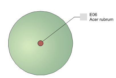
Existing TreesThe Vectorworks Landmark product includes the Existing Tree tool, for documenting the existing trees on a site. Details about each tree can be provided, including information such as species, condition, life expectancy, significance, and action to be taken. The 2D and 3D appearance of the trees can be specified, indicating the root and tree protection zones, with detailed plant ID tags and graphics for retained and removed trees, and the ability to select a 3D trunk and canopy shape. A report including the relevant information can be automatically created.
Click here for a video tip about this topic (Internet access required).
~~~~~~~~~~~~~~~~~~~~~~~~~
 Existing
Tree Workflow
Existing
Tree WorkflowWhen placing existing trees into the drawing, the following workflow is recommended:
• Initialize the plant database if it has not yet been opened, by selecting Landmark > Choose VW Plants. See “Specifying Existing Tree Species Information” on page 823 and “The Plant Database” on page 803. This action populates the list of existing trees so that species information can be selected.
• Click the Existing Tree tool from the Site Planning tool set, and then select Preferences from the Tool bar to open the Object Properties dialog box for the existing tree. Set the defaults for the placement of existing trees, including automatic numbering, ID tag, 2D and 3D appearance (including the selection of 2D component symbols), and species information.
• While setting the default properties for the Existing Tree tool, specify classing wherever possible to be able to control the visibility of classed elements (easily accomplished from the Navigation palette) as well as specify appearance by class for many of the elements.
• Select Tools > Organization to open the Organization dialog box. On the Classes tab, navigate to the classes related to the existing tree, and specify their appearance. Classes should be set to Use at Creation. For canopy and trunk classes, set the texture (Renderworks required) or color to display in 3D views. Set the marker and line style of the tag class if a marker is to be displayed.
• When placing existing trees, keep in mind that the selected 2D component symbols will not display until an Action has been specified. This helps you determine at a glance which trees still require an action to be set.
• The parameters of groups of selected trees, or trees on a specific layer, or all trees can be set in a single operation by using the Apply Properties in the various existing tree dialog boxes.
• Indicate the location of important and less important areas of the site by specifying the significance of each tree or group of trees.
~~~~~~~~~~~~~~~~~~~~~~~~~
 Placing
Existing Trees
Placing
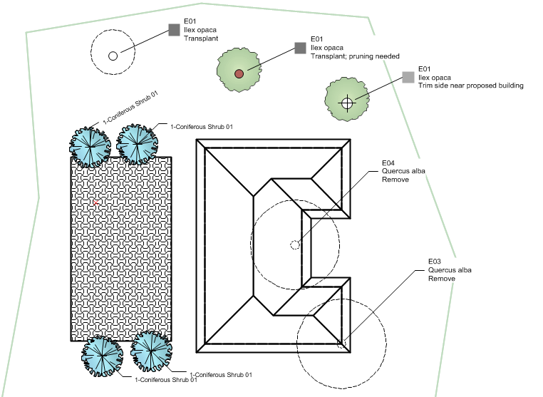
Existing Trees
To place an existing tree:
1. Click the Existing Tree tool from the Site Planning tool set.
If this is the first time the object has been placed in this session, the Object Properties dialog box opens. Set the default existing tree properties before placing trees, or place the tree and then edit its parameters in the Object Info palette.
2. Click in the drawing to place the existing tree. Click again to set the rotation.
The appearance of the existing tree may not match its 2D settings until certain parameters have been specified in the Object Info palette. For example, until the Action is specified, the tree does not display with the symbol set for Retain or Remove; the significance must be set for the significance color to display.
The existing tree properties can be edited from the Object Info palette.
Click to show/hide the parameters.
~~~~~~~~~~~~~~~~~~~~~~~~~
 Specifying Existing
Tree Species Information
Specifying Existing
Tree Species InformationThe species information for existing trees is obtained from the Vectorworks plant database; see “The Plant Database” on page 803. If the plant database has not yet been opened, its default location needs to be set.
To specify botanical data from the Vectorworks plant database:
1. If it has not yet been opened, initialize the plant database by selecting the Choose VW Plants command from the appropriate menu:
• Designer: AEC > Plants > Choose VW Plants
• Landmark: Landmark > Choose VW Plants.
The Choose Plant Database Location dialog box opens. Select the plant database location as described in “Accessing the Plant Database” on page 804.
By default, all plants in the tree Category of the database are included in the Species Data dialog box for access by the Existing Tree tool. If desired, search the plant database for the trees you require, and then select the File > Create ‘Existing Tree’ List database command. This customizes the existing tree list to use only the plants found in the database search.
2. From the Object Info palette of a selected existing tree, click Get Species Data.
The Species Data dialog box opens, listing tree species information. Species can be easily added to the list.
If the list is blank, the plant database location was not initialized.
Click to show/hide the parameters.
3. Select the species from the list, and click OK.
The Object Info palette displays the species information.
~~~~~~~~~~~~~~~~~~~~~~~~~
 Setting
2D Existing Tree Appearance
Setting
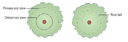
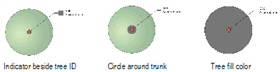
2D Existing Tree AppearanceThe 2D appearance controls the symbol for the tree and trunk, and also sets the attributes of the significance status, primary and critical root zones, and tree protection zones. The settings apply to the selected tree or a variety of other selection options, and can be set as the default 2D attributes for the drawing. This is a powerful way to control the 2D appearance of all existing trees in the layer or drawing in one operation.
Using classes for the significance colors, root zone, and tree protection zone is recommended. The visibility of these elements is easy to control with classes. See “Classes” on page 172.
Existing tree symbols are provided as default content (default content is automatically imported into the current file at the point of use and displays in the Resource Browser; see “Resource Libraries” on page 215). The resources in the ET Symbols.vwx file are available in the 2D Properties dialog box.
To set the existing tree 2D appearance:
1. From the Object Info palette of a selected existing tree, select 2D Properties. Alternatively, double-click on an existing tree.
The 2D Properties dialog box opens.
Click to show/hide the parameters.
2. Click OK.
Certain 2D properties depend on selections made in the Object Info palette for each existing tree, and are not applied immediately. For example, the symbol specified in Tree Remove does not display unless Remove is selected as the Action for the tree.
The symbols for retained and removed trees are scaled by the canopy height and diameter specified in the Object Info palette. The original and proposed symbols for a transplanted tree are scaled by the DBH parameter.
~~~~~~~~~~~~~~~~~~~~~~~~~
 Specifying
the Tree Protection Zone
Specifying
the Tree Protection ZoneThe tree protection zone is the area around the tree that should be fenced off, or preserved, to protect the tree. The tree protection zone moves with the tree trunk location. The zone can be irregular or circular; irregular zones can be reshaped. The TPZ Area displays the calculated area for the entire tree protection zone.
To specify the tree protection zone:
From the Object Info palette of a selected existing tree, select the type of tree protection zone.
Click to show/hide the parameters.
An irregular tree protection zone may need to extend beyond the initial boundary shape. To reshape the tree protection zone:
1. Select Edit Irregular Zone from the Tree Protection parameter.
The tree protection zone displays with editing handles.
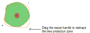
2. Drag the handles to reshape the zone. Adjust the radius at the corners of the zone with the TPZ Cnr Radius value, which only displays during zone editing.
3. When reshaping is finished, select Display Irregular Zone from the Tree Protection parameter.
~~~~~~~~~~~~~~~~~~~~~~~~~
 Specifying
an Irregular Canopy
Specifying
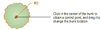
an Irregular CanopySince trees are not always perfectly symmetrical, the Existing Tree tool allows an irregular canopy shape to be defined by setting the measurements, in four different directions, from the center of the trunk to the edge of the canopy.
If the trunk had previously been repositioned by moving its control point, it is reset to the default position when an irregular canopy is selected. The trunk cannot be offset for irregular canopy shapes.
To specify an irregular canopy shape:
1. From the Object Info palette of a selected existing tree, select Irregular Canopy.
The Irregular Canopy Size dialog box opens. Specify the canopy size in four directions.
Click to show/hide the parameters.
2. Click OK. The 2D and 3D appearance of the tree displays with an irregular canopy shape, roughly based on the selected symbol definition.
The irregular shape can be oriented differently by entering a North Angle offset in the Object Info palette.
~~~~~~~~~~~~~~~~~~~~~~~~~
 Setting 3D
Existing Tree Appearance
Setting 3D
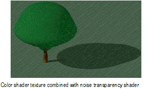
Existing Tree AppearanceThe 3D appearance controls the symbol for the tree and trunk in 3D views. The settings apply to the selected tree or a variety of other selection options, and can be set as the default 3D attributes for the drawing. This is a powerful way to control the 3D appearance of all existing trees in the layer or drawing in one operation. Showing trees in a 3D view is also useful for creating shadow diagrams (Renderworks required).
Using classes for the tree canopy shape and trunk is recommended. The attributes (color or texture) of these elements are easy to control with classes (Renderworks is required to use textures). The class color or texture must be set to Use at Creation. See “Classes” on page 172.
Existing tree symbols are provided as default content (default content is automatically imported into the current file at the point of use and displays in the Resource Browser; see “Resource Libraries” on page 215). The resources in the ET Symbols.vwx file are available in the 3D Properties dialog box.
Image props, such as those provided by xFrog, can be used as 3D tree geometry. However, canopy height and canopy diameter changes in the Object Info palette do not affect the geometry of image props.
To set the existing tree 3D appearance:
1. From the Object Info palette of a selected existing tree, select 3D Properties.
The 3D Properties dialog box opens.
Click to show/hide the parameters.
2. Click OK.
The 3D canopy shape is affected by changes in the Object Info palette for height, diameter, irregular canopy shape, First Branch Hgt, and DBH values.
~~~~~~~~~~~~~~~~~~~~~~~~~
 Existing
Tree Autonumbering and ID Tags
Existing
Tree Autonumbering and ID TagsExisting tree tags can contain an automatic numbering ID as well as tree information. Set up the new tree autonumbering properties first, to automatically number the trees according to the settings as they are placed on the drawing. Autonumbering can also be changed after placement on a tree-by-tree basis.
To set autonumbering and ID tag information for existing trees:
1. From the Object Info palette of a selected existing tree, select Tag and Number Options.
The Tag and Number Options dialog box opens.
Click to show/hide the parameters.
2. Click OK.
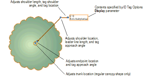
Existing tree tag appearance and placement is flexible, and can be adjusted in several ways, including through the Object Info palette, tag class settings, and the control point locations on the drawing.
• When existing tree tags are required, define their appearance in the Tag and Number Options dialog box. Apply the ID tag options to all existing trees and to the document defaults.
• Individual tags can then be changed for selected existing trees by clicking Tag and Number Options from the Object Info palette. For example, selected trees in one area of a planting plan look more uniform when they all use the same tag approach and tag shoulder angle. Set the Shoulder Angle and then select Also apply position of ID tag.
• The existing tree tag class controls the appearance of the leader/shoulder lines, as well as the marker style.
• To move the plant tags of several selected plants at once, click the Unrestricted Interactive Scaling mode of the Selection tool.
• If an individual tag needs to be repositioned, plant tags also have several control points for adjusting the tag text and leader line and shoulder position and angle.
• Align and distribute the leader lines for improved readability with the Align/Distribute Leader Lines command (see “Aligning and Distributing Leader Lines” on page 1033)
~~~~~~~~~~~~~~~~~~~~~~~~~
 Customizing
Existing Trees
Customizing
Existing TreesExisting trees are hybrid symbols, containing a 2D symbol component, and optionally, a 3D symbol component. The default existing tree symbols are located in the default content included with the Vectorworks Landmark product in Vectorworks\Libraries (see “Resource Libraries” on page 215). As 2D and 3D settings are made, the associated tree symbols are automatically imported into the current file and appear in the Resource Browser.
As with any resource, the symbols can be edited through the Resource Browser, and these edits apply to the current file. Alternatively, custom existing tree symbols can be added to the default ET Symbols.vwx file, either directly or by exporting edited tree symbols to the file (duplicate and rename the symbols from the Resource Browser first, so that the original symbols are not overwritten). For more information on symbol operations in the Resource Browser, see “Trabalhando com Recursos” on page 221. See “Exporting Custom Resources” on page 229 for information on exporting resources.
These naming conventions ensure that any custom symbols are available for selection in the 2D and 3D Properties dialog boxes:
• Symbol names for retained trees, or the new location of transplanted trees, must begin with 1. (the number 1, followed by a period)
• Symbol names for removed trees, or the original location of transplanted trees, must begin with 2.
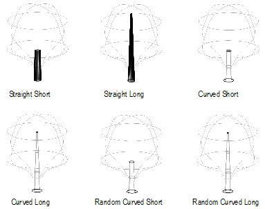
• Symbol names for the 2D tree trunk must begin with 3.
• Symbol names for the 3D canopy must begin with 4.
~~~~~~~~~~~~~~~~~~~~~~~~~
 Plant Graphics
In addition to plant placement with the Plant tool, there are additional ways of representing plant masses on a planting plan. Large, defined planting areas containing specific plants can be created with the Landscape Area tool. Undefined plant masses and groups can be added with the Plant Line and Vegetation Line commands. To further change the appearance of the planting plan, all plant styles can be displayed or hidden.
~~~~~~~~~~~~~~~~~~~~~~~~~
 Creating
Landscape Areas
Creating
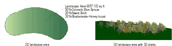
Landscape AreasLandscape areas consist of large, defined regions of plant combinations, useful for conceptual planning and specifying large planting or reforestation areas, when individual plant symbols do not need to be drawn. Plant information from a landscape area is based on plant symbol data, and is included in plant list worksheets. If a site model is present, the landscape area is calculated based on the site model and displays in the Landscape Area Settings dialog box.
A landscape area can also be created without plant information specified, for use as a general ground cover or mulch area with a label showing the total area required.
Landscape area objects can also be created by drawing a polyline and then selecting the Create Objects from Shapes command (see “Creating Objects from Shapes” on page 273).

To create a landscape area:
1. Click the Landscape Area tool from the Site Planning tool set.
2. Click Preferences from the Tool bar to specify or change the default landscape area parameters.
The Landscape Area Settings dialog box opens.
Click to show/hide the parameters.
3. Specify the plants included in the landscape area, as well as their frequency. Click Add to specify or Edit to change an included plant and its distribution rate or percentage value. The total percentage of all plants in the landscape area should be 100 when finished.
The Edit Landscape Area Information dialog box opens.
Click to show/hide the parameters.
4. Click OK, and then click OK again to close the Landscape Area Preferences dialog box.
5. Click on the appropriate mode in the Tool bar to select the boundary creation method of the landscape area.
For more information on the Polyline tool modes, see “Creating Polylines” on page 294.
6. Click to set the landscape area’s start point.
7. Click to set the end of the segment and the beginning of the next. Continue drawing segments in this manner until the landscape area object is complete.
The appearance of the landscape area is controlled by several methods.
• Change the landscape area parameters from the Object Info palette, including specifying a general unit price (for indicating the price per square unit in worksheets), price code (such as a SKU number) and vertex parameters; click Landscape Area Settings from the Object Info palette to change landscape area information and other preference parameters
• Change the landscape area 2D attributes from the Attributes palette
• Change the landscape area tag appearance by editing its parameters in the Object Info palette, editing the tag class properties, and/or moving tag control points (similar to a plant tag; see “Plant Tag Appearance” on page 800)
• To align landscape area tags for improved readability, use the Align/Distribute Leader Lines command (see “Aligning and Distributing Leader Lines” on page 1033).
• Reshape the landscape area by double-clicking on it. The Reshape tool is automatically activated, to reshape the object directly in the drawing.
• Right-click (Windows) or Ctrl-click (Mac) on the landscape area object and select Edit from the context menu. The Edit Landscape Area dialog box opens. Either edit the settings of the selected landscape area, or edit the shape of the object path with the Reshape tool.
Click here for a video tip about this topic (Internet access required).
~~~~~~~~~~~~~~~~~~~~~~~~~
 Creating
a Custom Landscape Area Tag
Creating
a Custom Landscape Area TagIn addition to providing several predefined landscape area tags, Vectorworks Landmark allows designers to create custom landscape area tags.
1. From the Tag Information pane of the Landscape Area Settings dialog box, select Set Custom Tag from either the Tag Header or Tag Body fields. Settings for the landscape area tag currently displaying in this field are displayed in the Set Custom Tag dialog box.
The Set Custom Tag dialog box opens.
If editing an existing tag through the Object Info palette, the selected tag’s data displays.
2. Select values from the predefined plant record fields (including an empty string to skip the field value) in the order they should be listed, and type the delimiter text that will appear between values. A combination of up to six landscape area values and plant record fields can be specified for the Tag Header and Tag Body fields.
The Tag Appearance field displays a static text preview of the custom tag. To preview a long tag in its entirety, Click-drag the bottom right corner of the dialog box to resize it.
3. Click OK.
~~~~~~~~~~~~~~~~~~~~~~~~~
 Creating
a Plant Line
Creating
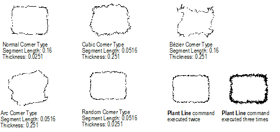
a Plant LineThe Plant Line command creates a freehand plant line along a line, polyline, or polygon. It can be used to represent a single undefined plant, line of plants, or general plant mass. No specific plant symbol information is included in a plant line; use the Landscape Area tool if defined plant areas are necessary (see “Creating Landscape Areas” on page 833).
To create a plant line:
1. Select the object (line, polyline, or polygon) with the Selection tool.
2. Select the Plant Line command from the appropriate menu:
• Designer: AEC > Plants > Plant Line
• Landmark: Landmark > Plant Line
The Plant Line dialog box opens. Suggested values are based on the selection’s perimeter.
Click to show/hide the parameters.
3. Select the desired plant line parameters and click OK. The plant line is created. If desired, apply colors, textures, and other attributes to the plant line with the Attributes palette.
~~~~~~~~~~~~~~~~~~~~~~~~~
 Creating
a Vegetation Line
Creating
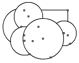
a Vegetation LineThe Vegetation Line command creates a vegetation line around a selection of closed objects or symbols. It can be used to represent a massed collection of undefined vegetation.
To create a vegetation line:
1. Select the closed objects or symbols that will form the basis of the vegetation line. The items should overlap.
2. Select the Vegetation Line command from the appropriate menu:
• Designer: AEC > Plants > Vegetation Line
• Landmark: Landmark > Vegetation Line
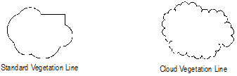
The Vegetation Line dialog box opens. Select the type of vegetation line to create, and whether the original objects should be deleted or retained.
Click to show/hide the parameters.
3. Click OK to create the vegetation line. If desired, apply colors, textures, images, hatches, gradients and other attributes to the vegetation line with the Attributes palette. See “The Attributes Palette” on page 1091 for more information on applying attributes.
The vegetation line can be assigned to a class (with the desired attributes). The original plant symbols can remain hidden by a vegetation line with a solid fill; however, the underlying vegetation can be revealed by hiding the vegetation line class.
 Show/Hide
Plant Styles
Show/Hide
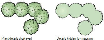
Plant StylesThe Show or Hide Plant Styles command controls the visibility of the outline, massing, and shadow parameters set on the Render pane of a plant definition (see “Plant Definition: Render Pane” on page 789), on the Render pane of the plant settings (see “Plant Settings: Render Pane” on page 797), as well as on the Object Info palette.
These effects display in Top/Plan view only. In a complex drawing with many plants, these settings can take a significant amount of time to display and edit, and it is useful to toggle the effects on and off.
To show or hide the plant styles:
1. Select View > Show > Show or Hide Plant Styles.
2. If the plant styles are currently hidden, this command displays the outline, massing, and shadows of all plant objects with those parameters set.
If the plant styles are currently visible, this command hides the effects. The Outline selection is saved for the plants, even when hidden.