 Creating Slabs
The Floor command can be used to create not only floors, but also decks, patios, stages, platforms, and lofts. The command converts any 2D drawing object into a hybrid (2D/3D) object of any shape and thickness. The source object must be flat and must also be parallel to the active layer plane.
To create a floor:
1. Select the 2D object to turn into a floor.
2. Select the Floor command from the appropriate menu:
• Fundamentals: Model > AEC > Floor
• Architect: AEC > Floor
• Landmark: Landmark > Architectural > Floor
• Spotlight: Spotlight > Architectural > Floor
The Create Floor dialog box opens.
Click to show/hide the parameters.
3. Click OK.
~~~~~~~~~~~~~~~~~~~~~~~~~
Creating SlabsThe Slab tool, available in the Vectorworks Architect product, creates architectural floor slabs. Slabs can be drawn manually or they can be based on, and associated with, an existing set of walls. The method of associating slab components with wall components can be specified, to create accurate and detailed cross-section views.
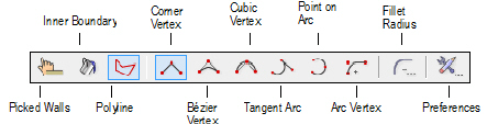
To draw a free-standing slab manually with the Slab tool, select the Polyline mode. If the walls are already drawn, select the Picked Walls mode or Inner Boundary mode to create a slab bounded by visible walls.
Mode |
Description |
|---|---|
Picked Walls |
Defines the perimeter of a slab based on a closed set of selected walls |
Inner Boundary |
Creates a slab object in a clicked area that is bounded by visible walls |
Polyline |
Draws a polyline slab object; as with a polyline, select one of six types of control points for the vertices from the Tool bar |
Corner Vertex |
For Polyline mode, creates the slab using polyline segments with straight lines and angled vertices at the control points |
Bézier Vertex |
For Polyline mode, creates the slab using polyline segments with curves pulled toward, but not touching the control points |
Cubic Vertex |
For Polyline mode, creates the slab using polyline segments with curves that pass through the control points |
Tangent Arc |
For Polyline mode, creates the slab using polyline segments that are tangent to the previous segment |
Point on Arc |
For Polyline mode, creates the slab using polyline segments that are drawn by clicking three points: the start point, a point the arc passes through, and the end point |
Arc Vertex |
For Polyline mode, creates the slab using polyline segments with curves that look like a fillet placed at the control points |
Fillet Radius |
For Polyline mode, sets the fillet radius when the Arc Vertex mode is selected |
Preferences |
Sets the default parameters that are used for each slab object |
~~~~~~~~~~~~~~~~~~~~~~~~~
 Drawing
Slabs Manually
Drawing
Slabs Manually
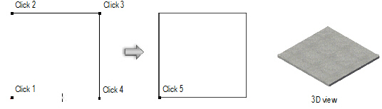
To draw a manual slab object that is not associated with any walls:
1. Click the Slab tool from the Building Shell tool set, and select Polyline mode from the Tool bar.
2. To draw an unstyled slab, select <Unstyled> from the Slab Style list on the Tool bar. To create a styled slab, select it from the Tool bar Slab Styles list, which displays the slab style resources in this file as well as default slab styles. Create a new slab style by clicking Preferences from the Tool bar; see “Creating Slab Styles” on page 482.
3. Select a polyline drawing mode. See “Polyline Tool” on page 294.
A slab can also be created by drawing a polyline and then selecting the Create Objects from Shapes command (see “Creating Objects from Shapes” on page 273).
4. Similarly to drawing a polygon, create a closed slab shape.
Double-click while drawing to close the slab automatically.
Every slab contains a component designated as the datum component. The top of this component is the Z-reference datum, and is fixed vertically (it does not change with any changes to the slab thickness or definition). The reference datum of the slab can be set to the active layer elevation value, or set to be bound by one of the story levels defined for the story or the story below it. By setting the slab datum to a level type, if the elevation of the associated story changes, the datum of the slab changes automatically to match.
~~~~~~~~~~~~~~~~~~~~~~~~~
 Creating
Automatically Bounded Slabs from Existing Walls
Creating
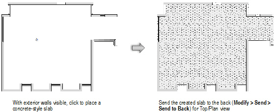
Automatically Bounded Slabs from Existing WallsSlabs can be automatically created by first selecting the enclosing walls or by clicking within the boundary of a closed set of visible walls. The slabs are automatically associated with their bounding walls.
Use classes to distinguish interior and exterior walls to easily place slabs associated with the correct wall set.
Every slab contains a component designated as the datum component. The top of this component is the Z-reference datum, and is fixed vertically (it does not change with any changes to the slab thickness or definition). The reference datum of the slab can be set to the active layer elevation value, or set to be bound by one of the story levels defined for the story or the story below it. By setting the slab datum to a level type, if the elevation of the associated story changes, the datum of the slab changes automatically to match.
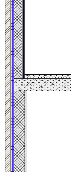
The slab edge path is defined by the outside or inside face of the walls, or by components within the wall, as defined by the slab component properties. If the walls are edited (whether moved, reshaped, or replaced, or due to a change in the wall style, the wall thickness, or the wall components), the slab edge path updates automatically. However, if the walls are edited so significantly that the slab cannot retain its association, you have the option to create a manual slab from the automatically bounded slab.
Because the walls and slab are associated, section views display accurately. When creating a section view, similar component fills can be merged to display as a single unit (see “Advanced Sheet Layer Viewport Properties” on page 1638).
Once an automatically bounded slab is created, it can be moved to another layer and still retain its association with the walls.

To create an automatically bounded slab within a selected set of visible walls:
1. Click the Slab tool from the Building Shell tool set, and select Picked Walls mode from the Tool bar.
2. To draw an unstyled slab, select <Unstyled> from the Slab Style list on the Tool bar. To create a styled slab, select it from the Tool bar Slab Styles list, which displays the slab style resources in this file as well as default slab styles. Create a new slab style by clicking Preferences from the Tool bar.
3. Click on each wall that forms the wall set and press Enter, or click the check mark button on the Tool bar.
4. The slab is created.
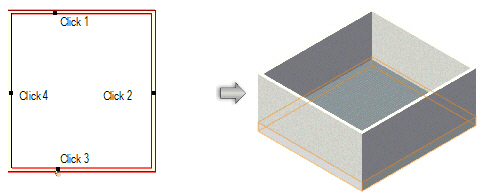

To create a slab within a closed set of visible walls:
1. Click the Slab tool from the Building Shell tool set, and select Inner Boundary mode from the Tool bar.
2. To draw an unstyled slab, select <Unstyled> from the Slab Style list on the Tool bar. To create a styled slab, select it from the Tool bar Slab Styles list, which displays the slab style resources in this file as well as default slab styles. Create a new slab style by clicking Preferences from the Tool bar.
3. Click in an open area of the drawing that is bounded by walls; the walls must be visible, joined together, and on layers that have the same layer scale as the slab layer.
4. The slab is created.
Click here for a video tip about this topic (Internet access required).
~~~~~~~~~~~~~~~~~~~~~~~~~
 Converting
Slab Boundary Associations
Converting
Slab Boundary AssociationsManually drawn slabs can be associated with a set of walls, converting them to automatically bounded mode. Similarly, an automatically bounded slab can be associated with a new set of walls by this method.
To convert manual slabs to automatically bounded slabs:
1. Select the manual slab. In the Object Info palette, the Bounding mode displays Manual.
2. Click Pick Boundary from the Bounding list.
The Slab tool is automatically activated, and Inner Boundary mode is selected (Picked Walls mode can also be selected).
3. For Inner Boundary mode, click in an open area of the drawing that is bounded by walls. For Picked Walls mode, click on each wall that forms the wall set and press Enter, or click the check mark button on the Tool bar.
4. The manual slab is associated with the wall set. Its location and size may change as it is bounded by the wall set.
Automatically bounded slabs can be converted to manual mode, releasing them from their association with walls.
To convert automatically bounded slabs to manual slabs:
1. Select the automatically bounded slab. In the Object Info palette, the Bounding mode displays Auto-Bounded.
2. Click Manual from the Bounding list.
3. The slab is disassociated from its wall set, though it remains in place.
~~~~~~~~~~~~~~~~~~~~~~~~~
 Using
Slab Styles
Using
Slab StylesUnstyled slabs can be created; in a new file, the default unstyled slab includes a single component. The attributes of an unstyled slab can be changed from the Attributes palette. The use of slab styles, however, facilitates drawing slabs by saving the slab preferences settings so that they can be easily applied to other slabs. Slab styles are resources that can be imported into other files and shared as office standards. Slab styles, textures, and hatches are provided as default content (default content is automatically imported into the current file at the point of use and displays in the Resource Browser). Setting and saving the dynamic height information of a slab in its slab style is a convenient way of automatically setting the defined height condition when using slabs with stories.
If a selected slab style’s parameters are edited, the slab style automatically changes to unstyled, indicating that the edited style must be saved as a new style to save changes (alternatively, the changes can be applied as an unstyled slab, and not get saved).
Unused slab styles can be purged; see “Purging Items from a File” on page 1009.
~~~~~~~~~~~~~~~~~~~~~~~~~
 Creating
Slab Styles
Creating
Slab Styles
To create a slab style:
1. Click the Slab tool from the Building Shell tool set, and click Preferences from the Tool bar.
The Slab Preferences dialog box opens.
Click to show/hide the parameters.
2. Click Edit Slab Attributes to define the slab attributes in Top/Plan view.
The Slab Attributes dialog box opens. The slab attributes of an unstyled slab are initially set to the parameters displayed in the Attributes palette. If they are changed here, the Attributes palette reflects the changed attributes of the selected slab (after exiting the Slab Preferences dialog box).
Fill, pen, and opacity can be set by class rather than by the attributes in the Slab Attributes dialog box. If the slab class is changed later, the slab changes to use the attributes of the new class. Slab attributes cannot be overridden on a per-instance basis; if a slab style uses class attributes, all slabs of that style must use class attributes. However, slabs of the same slab style can be placed in different classes.
Click to show/hide the parameters.
3. Click OK to return to the Slab Preferences dialog box.
4. Click the Insertion Options tab to set the slab insertion options.
Click to show/hide the parameters.
5. Click the Textures tab to select textures for the slab parts (Renderworks required).
Click to show/hide the parameters.
6. Click the Data tab to specify slab record information, which is IFC-compliant and can be included in a slab style schedule. These fields are optional; enter text only where desired.
7. Click Save Preferences as Slab Style.
The Assign Name dialog box opens.
8. Enter a unique name for the slab style and click OK.
If the slab style name already exists, you are prompted to cancel and select a different name, or replace existing slabs with the slab style applied with the edited slab style. If you are replacing slab styles, the Slab Replacement dialog box opens; specify the slab replacement properties.
9. The new slab style is saved with the file and is listed under Slab Styles in the Resource Browser as well as the Slab Style list in the Tool bar.
A new slab style can also be created by clicking Resources > New Resource > Slab Style in the Resource Browser. A slab style created in this way is not associated with the current slab preference setting, but can be applied later.
~~~~~~~~~~~~~~~~~~~~~~~~~
 Editing
Slab Styles
Editing
Slab StylesTo edit a slab style:
1. Select the slab style from the Resource Browser and click Resources > Edit.
The Edit Slab Style dialog box opens.
2. Edit the slab and component parameters.
If a new slab style Name is specified, it replaces the selected slab style name (similar to selecting Rename from the Resources menu).
3. Click OK.
4. If slabs with that style already exist in the drawing, the Slab Replacement dialog box opens.
The slab style to apply cannot be selected (the edited style is applied).
5. Click OK to edit the slab style.
Changes apply to any existing slabs in the drawing with the edited slab style, and will be used for any subsequent slabs created with that slab style.
~~~~~~~~~~~~~~~~~~~~~~~~~
 Applying
Slab Styles
Applying
Slab StylesBy a variety of methods, slab styles can be selected for a slab before drawing it, or applied to existing slabs. Once a slab style has been selected for a slab, the Attributes palette is no longer available for changing slab attributes; attributes are set as part of the style.
To apply a slab style prior to creating the slab:
1. Select the Slab tool from the Building Shell tool set.
2. Select the desired style from the Slab Style list on the Tool bar. The available slab styles are from either the default content or the current file’s content.
Alternatively, click Preferences from the Tool bar. In the Slab Preferences dialog box, select the Slab Style.
To apply a slab style from the Resource Browser prior to drawing the slab:
1. Ensure that no slabs are selected.
2. Select a slab style in the Resource Browser, and click Resources > Apply.
Alternatively, double-click on the slab style in the Resource Browser.
3. The Slab tool is automatically made active and the selected slab style is applied to the slab as it is drawn.
To apply a slab style to an existing slab from the Object Info palette:
1. Select one or more slabs.
2. From the Object Info palette, select the slab Style. To apply a different (default) style, select Replace.
To apply a slab style to an existing slab from the Resource Browser:
1. Select one or more slabs.
2. Select the slab style from the Resource Browser and click Resources > Apply. Alternatively, drag the selected slab style from the Resource browser to the slab and click on the slab selection.
The Slab Replacement dialog box opens. The slab style list is disabled (the style selected in the Resource Browser is applied).
3. Click OK.
A styled slab can be converted to an unstyled slab.
To remove a slab style:
1. Select one or more slabs to un-style.
2. From the Object Info palette, select Convert to Unstyled Slab.
The slab is released from its style; its attributes can be edited from the Attributes palette.
~~~~~~~~~~~~~~~~~~~~~~~~~
 Replacing
Slab Styles
Replacing
Slab StylesSlab styles applied to existing slabs can be replaced with a different slab style.
A slab replacement situation may also occur if pasting a styled slab from another file.
To replace a slab style:
1. Select one or more slabs.
2. From the Object Info palette, select Replace from the Style list.
The Slab Replacement dialog box opens. Specify the new slab style. The red line indicates the datum component of each slab style; replacement is aligned to the datum.
Click to show/hide the parameters.
If slabs with different slab styles were selected for replacement, the current slab preview is blank and components do not display.
3. Click OK to replace the slab style of the selected slab(s).
~~~~~~~~~~~~~~~~~~~~~~~~~
 Creating Slab Components
Slab components define the sections that make up a slab. For example, to indicate that a slab is made up of gypsum board ceiling, wood framing, and a plywood deck, define a component for each of these items to illustrate their location. Slab components can be offset from the edges of the walls (automatically bounded slabs) or the edge of the slab (manual slabs); their appearance can be specified for cross-section views, and they can be textured (Renderworks required), creating realistic section views and rendered views, as well as accurate slab material estimates. The area and volume of slab components (minus any holes cut) can be calculated in worksheets; see “Worksheet Functions” on page 1340).
The overall thickness of a slab is equal to the sum of its components. Component fill and pen style are only displayed in section viewports.

To define slab components prior to drawing the slab:
1. Click the Slab tool from the Building Shell tool set, and click Preferences from the Tool bar.
The Slab Preferences dialog box opens.
2. On the Definition tab, click New.
The Slab Component Settings dialog box opens. Specify the component name, thickness, edge offset, and appearance in section views and rendered views.
Click to show/hide the parameters.
3. Click OK to create the component and return to the Slab Preferences dialog box.
The slab’s Overall Thickness value changes to be determined by its components. As components are defined, they display in the preview. Click and drag a component in the # column to change its order.
4. To save the component settings with the slab settings as a slab style, click Save Preferences as Slab Style.
5. Click OK.
Once created, the components of a selected slab can be edited by clicking Components from the Object Info palette.
To define or edit slab components for an existing, unstyled slab:
1. Select the slab(s).
2. From the Object Info palette, click Components.
The Components dialog box opens.
Click to show/hide the parameters.
3. Click New or Edit, and define or edit the components as described in “Creating Slab Components” on page 487.
4. Click OK to return to the Components dialog box.
5. Click OK. The new component definition is applied to the selected slab(s).
~~~~~~~~~~~~~~~~~~~~~~~~~
 Editing
Slabs
Editing
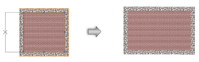
SlabsSlabs are path-based objects and can be reshaped, added to, and clipped. For example, a slab may need a hole clipped to accommodate a flight of stairs, or may need area added to represent a balcony.

To reshape a slab:
1. Click the Reshape tool from the Basic palette.
Alternatively, double-click on the slab to activate the Reshape tool.
2. Click one of the modes from the Tool bar.
See “Remodelando Objetos” on page 1041.
3. The datum component is selected for reshaping; any editing applies to the entire slab.
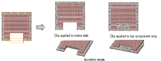
When clipping a slab, select whether the clip operation should affect the entire slab or only certain components.
To clip a slab:
1. Create a closed 2D object to represent the clipping object. The object must overlap the slab.
2. Select both the slab and the clipping object.
3. Select Modify > Clip Surface.
4. The Clip shape from slab dialog box opens. Select whether to clip the entire slab, or choose the components to be clipped by selecting them.
5. Click OK.
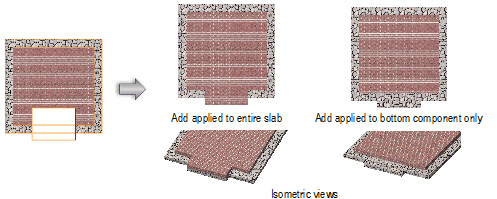
When adding to a slab, select whether the add operation should affect the entire slab or only certain components.
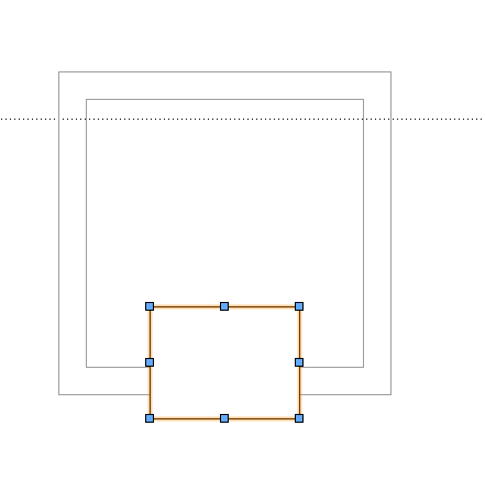
To add to a slab:
1. Create a closed 2D object to represent the add surface. The object must overlap the slab.
2. Select both the slab and the add surface object.
3. Select Modify > Add Surface.
4. The Add Shape to Slab dialog box opens. Select whether to add to the entire slab, or choose the components to be added to by selecting them.
5. Click OK.
The original editing object used to clip or add to the slab can be modified.
To modify the editing object:
1. Select the slab.
2. Select Modify > Edit Slab.
A colored border around the drawing window indicates that you are in an editing mode. The Exit Slab command becomes available from the Modify menu, and the Exit Slab button is visible in the top right corner of the drawing window. The editing object is selected.
3. Move, delete, or reshape the editing object (new editing objects cannot be added, however). The slab is locked and cannot be edited.
4. Click Exit Slab to return to the drawing.
~~~~~~~~~~~~~~~~~~~~~~~~~