 Equipamento
para Eventos e Análise EstruturalEquipamento
para Eventos e Análise Estrutural
Equipamento
para Eventos e Análise EstruturalEquipamento
para Eventos e Análise EstruturalThe design of rigging structures is an integral part of the event, entertainment, display, and exhibit industries. The Braceworks™ suite of commands and tools inserts and connects supporting structures (such as trusses and lighting pipes), adds hoists and other supports, and then adds loads to the structures.
With a Braceworks license, the system uses the Finite Element Analysis (FEA) to accurately calculate and analyze the structural forces of a hanging rigging system, to determine whether the structural system is viable. Structural reports and the ability to export in DSTV format allow the calculations to be shared and validated by structural engineering colleagues.
|
Clique aqui para uma dica em vídeo sobre este tópico (requer acesso à internet). |
 Braceworks-only
Functionality
Braceworks-only
FunctionalityVectorworks Spotlight incorporates many of the Braceworks features for drawing rigging structures and adding loads, allowing Spotlight users to take advantage of the rigging tools and run a system check (a Spotlight user may need to add the available commands to the workspace).
However, a Braceworks license is required to perform calculations and create reports.
The structural analysis calculations in Braceworks are done by an FEA core that performs calculations upon the rigging objects in the Vectorworks drawing (the truss, straight truss, curved truss, and lighting pipe). Each object is handled individually in the calculations; the FEA core considers all of the individual structural elements as beams. To determine the correct type of beam, each beam contains the cross section information required for proper calculations.
The following commands require a Braceworks license:
• Calculate All Objects |
• Create Calculation Report |
• Calculate Load Combinations |
• Braceworks Preferences |
• Calculate Visible |
• Calculation Overview |
• Calculate Selection |
• Cross Section Workload |
• Export DSTV |
• Scale Influence Lines |
In conjunction with Spotlight’s other tools and commands and features, lighting designers can use Braceworks tools as part of the design process, and rigging professionals can use the Braceworks tool set and commands to create, analyze, and report complete rigging designs. The suggested workflow will vary, depending upon the type of design, the venue, the event, and whether you have a Spotlight or Braceworks license.
Lighting designers planning to use Vision to previz the show can set up a file with Braceworks with little change to their current workflow. To reduce excess geometry, the use of the Straight Truss and Curved Truss tool as well as the Lighting Pipe tool is recommended. To keep lighting devices and other Spotlight design elements easier to work with, convert these items to hanging positions with the Convert to Hanging Position command.
• Collaborate with all departments involved with rigging elements.
• Specify the basics of the drawing, such as establishing the layer scale, creating layers, setting up Spotlight preferences, and so on. Create non-rigging elements for the drawing (stage objects, venue walls).
• Optional: Set up the truss inventory with the truss types and different truss lengths available, by selecting the Replace Truss command and clicking Truss Inventory.
• Braceworks required: Define the Braceworks Preferences.
• Create the rigging structure in the drawing space. Insert trusses with the Insert Truss tool. Auto Connect mode should be enabled so that the rigging elements create a system.
Alternatively, use the Straight Truss tool and/or the Curved Truss tool. Insert a lighting pipe with the Lighting Pipe tool. All of these elements are considered to be “beams” by Braceworks.
• If needed, add connections between structural elements. The Insert Connection tool creates hoists or truss cross connections between trusses.
• Convert geometry with the Convert to Hanging Position command. This allows the structural objects to also function as hanging positions for Spotlight lighting devices and other Spotlight objects.
• If needed due to inventory restrictions or other requirements, replace parts of the truss line with different lengths of truss with the Replace Truss command, or replace one truss type with another with the Replace Truss Type command.
• Add, or have the various departments add, the load objects such as lights, speakers, video screens and so on, or insert a point load or distributed load with the Insert Load tool. The auto-connect function snaps to the correct point. Loads are attached to hanging positions automatically, or can be added later. Any elements that are not needed for calculations (Braceworks required) should be kept on layers that are separate from the elements that will be calculated.
• Add support objects such as hoists or drops associated with a truss with the Insert Drop command.
• Use the Hoist tool to place hoists that support the system.
Number the hoists so that they have unique IDs in reports and calculations.
• Run the system check commands (first on selected, and then on all) to find any mistakes, such as unattached objects like loads or hoists, and misaligned or unsupported objects.
• Braceworks required: Correct any mistakes found. Braceworks provides color-coded annotations to assist with this, both in reports and within the drawing.
• Braceworks required: Hide the layers that do not participate in calculations, and then run the calculations first on a subset with the Calculate Selection command, and then on all visible items with the Calculate Visible command.
• Braceworks required: Make changes to the system as needed.
• Braceworks required: Run the calculations on all rigging items with the Calculate All Objects command to determine the viability of the system.
• Braceworks required: Make changes to the system as needed.
• Braceworks required: Create a report of the calculations.
• Braceworks required: Export reports if needed, sharing the data (PDF and/or DSTV file) with structural engineers, colleagues, or clients.
Braceworks calculations and, in some cases, functionality, depends upon creating connected rigging systems. As structural elements are placed in the drawing, they can automatically connect to other, similar elements with the same cross section, creating a system. Trusses, straight trusses, curved trusses, and lighting pipes can connect to form a system. Connected to those items, hoists and loads (including lighting devices, speakers, speaker arrays, video screens, soft goods, and generic point and distributed loads) are also considered to be part of the system, and they move or adjust with the system automatically.
It is important to use the method of Changing the Trim Height of a System to adjust the height of structural systems and all connected objects properly. All of the items in the system move together, and hoist chain lengths are automatically adjusted if needed.
When drawing with the Insert Truss tool, ensure that Auto Connect mode is enabled so that truss systems are automatically connected. Only compatible trusses can connect automatically. If the truss to connect does not cause an existing truss to highlight, it is because they are not compatible, or one of the structural elements does not have a valid Connectable to parameter.

In Auto Connect mode, trusses can only connect to compatible connectors:
• Spigot and connector plates can connect freely.
• Gable can only connect to a fork.
• Spigot male can only connect to spigot female.
At insertion, Auto Connect mode automatically flips gable, fork, spigot male/female trusses so that they connect properly. An alert opens only if a connection is not possible.
When adding other objects to the drawing, such as hoists and loads, valid connected structural elements are highlighted in red, indicating that if placed there, the new object will connect to the system. Copying and pasting trusses, rigging objects, and even entire systems also use auto connect functionality to connect to existing systems.
A completed rigging system consists of straight truss lines connected with corner elements to form a truss system, as shown in this simple illustration. Example naming of truss lines and the system is also shown; see Renaming Truss Systems for more information.

~~~~~~~~~~~~~~~~~~~~~~~~~
 Braceworks Preferences
Command |
Path |
|---|---|
Braceworks Preferences |
Braceworks |
Prior to beginning the rigging design, set up the default Braceworks preferences. The settings apply to the current file.
In addition to setting up the preferences, set up the Braceworks units on the Structural pane of the Units dialog box. If not specified, the document units are used.
To specify the Braceworks preferences:
1 Select the command.
The Braceworks Preferences dialog box opens.
2 Click the Calculation Settings tab.
► Clique para exibir/ocultar parâmetros.
3 Click the Classes tab to define the classes for various Braceworks elements for controlling appearance and visibility.
► Clique para exibir/ocultar parâmetros.
4 Click the Workload Display tab to specify color standards when generating a representative graphical workload gradient map after calculations are complete. This “heat map” display applies separately to hoists/bridles and trusses, and is visible in Top/Plan as well as 3D views.

► Clique para exibir/ocultar parâmetros.
~~~~~~~~~~~~~~~~~~~~~~~~~
 Creating the Rigging System
Tool |
Tool set |
|---|---|
Insert Truss
|
Rigging |
The Insert Truss tool places a section of truss on the drawing; depending on the resource selected, the truss may be straight, curved (or circular), or a corner element, and it may be horizontal or vertical. In Auto Connect mode, a truss connects to existing trusses, forming a truss system. When Auto Connect mode is disabled, the truss is not connected to an existing truss.
The following modes are available.

Mode |
Description |
|---|---|
Auto Connect |
When enabled, connects the inserted truss to the current truss system with geometrical precision; also generates a preview of connected trusses that are being moved |
Truss symbol |
Select the truss to insert |
Hanging Angle |
Specifies the hanging angle from the X axis |
Maintain class of symbol |
Uses the class specification from the symbol definition; disable the mode to insert the truss into the active class instead |
To insert a truss symbol:
1 Click the tool. Click Truss symbol on the Tool bar. From the Resource Selector, double-click a resource to activate it.
If a symbol is not selected, the Select Symbol dialog box opens automatically to select one.
Alternatively, from the Resource Manager, either double-click the truss symbol to insert or right-click on the truss symbol and select Make Active from the context menu. The Insert Truss tool is automatically selected.
If a truss symbol is accidentally inserted by the Symbol Insertion tool, the truss functionality will not be present. When correctly inserted, the Object Info palette displays “Truss” for the selected truss.
If the selected truss has insufficient information for proper calculations, the Truss Properties dialog box opens automatically, to enter required information; see Creating a Custom Truss Symbol.
Truss resources are organized by type, such as horizontal, vertical, curved, corner, etc. Select the desired type of truss element for insertion.
2 If this is the first truss placed, click to place the object in the drawing, and click again to set the orientation.
If connecting to an existing truss system, enable Auto Connect mode. When adding a truss to an existing system, a valid existing component to connect to is highlighted, indicating that if placed there, the new component will connect to the system. The Connectable with parameter determines whether structural elements can connect; trusses can only connect to compatible connectors, as described in Concept: Creating a Connected Rigging System. Move the mouse to hover over the connection; depending on the type of truss being attached and the view, various options are previewed for connecting the truss. For example, connecting a three way corner truss will have different insertion options available from connecting a four way truss, and Top/Plan view will provide different previews from 3D insertion. Auto Connect mode automatically flips gable, fork, spigot male/female trusses so that they connect properly.
When inserting vertical truss, switch to a 3D view, such as an isometric view. This allows truss sections to be added to either end, or to an existing corner element. If in Top/Plan view, truss sections can only be added to the top end. In Top/Plan or Top view, only the end of the truss is visible,
If no highlighting occurs with Auto Connect mode enabled, the trusses are not connectable.

When the desired location and orientation is highlighted, click to place the truss.
The truss properties can be edited from the Object Info palette.
► Clique para exibir/ocultar parâmetros.
~~~~~~~~~~~~~~~~~~~~~~~~~
 Creating
a Custom Truss Symbol
Creating
a Custom Truss SymbolCommand |
Path |
|---|---|
Convert to Truss |
Braceworks |
The Convert to Truss command is available for Vectorworks Spotlight software but is not present in the Spotlight workspace. It can be added to the Spotlight workspace (see Customizing Workspaces) and subsequently used to convert trusses.
Vectorworks Spotlight ships with a comprehensive set of truss symbols, but you can create a truss from your own symbol as well. Various parameters are required for truss symbols to be valid. Once the parameters have been set for the symbol, it is saved as a truss resource, so the parameters only need to be set one time.
If you are inserting a truss symbol that does not have all the required parameters for structural analysis, the Truss Properties dialog box opens automatically so that all necessary parameters can be set.
To convert a symbol to a valid truss:
1 Follow the steps in Criando Definições de Símbolos to create a hybrid symbol that serves as the basis of the truss.
2 Select an instance of the symbol.
3 Select the command.
The Truss Properties dialog box opens. Specify the parameters required for a valid straight, corner, or circular (curved) truss.
► Clique para exibir/ocultar parâmetros.
An alert opens; confirm whether to convert current instances of the symbol to trusses and create a truss resource by clicking Yes, or to only convert the currently selected instance and create a truss resource by clicking No.
A truss resource is created in the current file based on the original symbol and its specified data, and it can be selected from the Resource Manager or Resource Selector on the Tool bar for future placement in the drawing.
~~~~~~~~~~~~~~~~~~~~~~~~~
 Converting
a Truss into a Symbol
Converting
a Truss into a SymbolCommand |
Path |
|---|---|
Convert Truss to Symbol |
Braceworks |
The Convert Truss to Symbol command is available for Vectorworks Spotlight software but is not present in the Spotlight workspace. It can be added to the Spotlight workspace (see Customizing Workspaces).
If not performing Braceworks calculations, the use of many truss objects can be processor-intensive. For similar reasons as those explained in Vantagens dos Símbolos, you may wish to create a symbol out of a truss and use that in your drawing. However, trusses converted to symbols cannot participate in Braceworks calculations.
To convert a truss to a symbol:
1 Select the truss (or multiple truss objects) to convert.
2 Select the command.
An alert opens, informing you how many objects were converted.
Each type of truss is converted to a hybrid symbol. The symbol is named after the original truss name.
~~~~~~~~~~~~~~~~~~~~~~~~~
 Specifying Cross Section Data
All structural objects that participate in calculations, including truss, straight truss, curved truss, lighting pipes, and hoists, must have an associated file that contains cross section data.
Trusses with default manufacturer data include the cross section information, identified with a unique code from the manufacturer’s sets. If you are Creating a Custom Truss Symbol, either select a cross section by its code, or specify custom valid cross section information.
If not using a specific manufacturer cross section, a generic, rigid cross section can be selected. If not using a manufacturer or a generic cross section, specify custom cross section data.
A lighting pipe cross section is assumed to be a rigid cross section of the selected Construction Material chosen from the Object Info palette. A hanging position’s cross section data are based on the original object that was converted into a hanging position.
To select a cross section and/or specify cross section data:
1 Do one of the following:
• For a truss object, click Customize from the Object Info palette. From the appropriate tab of the Truss Properties dialog box, click Change Cross Section.
• From the Object Info palette of a straight truss or curved truss, click Truss Cross Section.
• From the Object Info palette of a hoist, click Chain Cross Section. The Chain Cross Section dialog box contains a subset of the parameters described here; see Placing Hoists.
The Cross Section dialog box opens.
► Clique para exibir/ocultar parâmetros.
2 For a truss object, click Apply Customization from the Object Info palette.
The cross section UID displays for the truss.
~~~~~~~~~~~~~~~~~~~~~~~~~
 Connecting Structural Elements
Tool |
Tool set |
|---|---|
Insert Connection
|
Rigging |
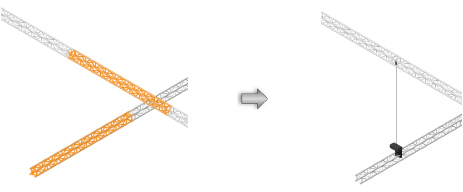
The Insert Connection tool either connects structural element sections with a drop (hoist) or stacks them with a truss cross connection. When stacking structural elements, you can choose to move the object to be stacked either up or down.
The following modes are available.

Mode |
Description |
|---|---|
Insert Drop |
Creates a connection between two structural elements by placing a hoist at the clicked point |
Places structure element on top |
Stacks a structural element above another one, moving a truss and all its associated supports and loads up to meet the reference truss. A truss cross is created at the connection point. |
Places structure element below |
Stacks a structural element above another one, moving a truss and all its associated supports and loads down to meet the reference truss. A truss cross is created at the connection point. |
To connect structural elements with one or more hoists:
1 Click the tool, and then click Insert Drop mode.
2 Click the structural element to connect.
3 Move the mouse to the structural element to be connected.
Valid connecting structures are highlighted, and a preview of the hoist location displays.
4 Click to place the hoist at that location and connect the structures.

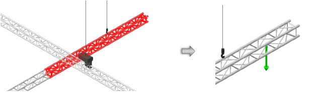
To connect structural elements to each other with a truss cross:
1 Click the tool, and then, depending on whether you want to move the structure up or down, click either Places structure element on top or Places structure element below mode.
2 Click on the reference structural element; this truss does not move.
3 Click on the structural element to move either up or down (stacking the moved truss under or over).
The truss is stacked with the reference truss, and any connected hoists, attached loads, and supports move with the truss. If hoists are connected between the trusses, they are removed; hoists connected to other truss sections may be lengthened or shortened.
A truss cross is automatically created at the connection point. A truss cross indicates how to calculate and model the connection between stacked trusses. Its appearance indicates the type of connection (whether it is connected, flexible, or rigid; can transmit all forces, or only tension or only compression forces, or no forces).

The truss cross properties can be edited from the Object Info palette.
► Clique para exibir/ocultar parâmetros.
~~~~~~~~~~~~~~~~~~~~~~~~~
 Inserting
Connections Automatically
Inserting
Connections AutomaticallyCommand |
Path |
|---|---|
Insert Drop |
Braceworks |
The Insert Drop command is available for Vectorworks Spotlight software but is not present in the Spotlight workspace. It can be added to the Spotlight workspace (see Customizing Workspaces).
Selected structural elements can be connected automatically with hoists at likely connection points with the Insert Drop command.
To connect structural elements automatically:
1 Select the two structural elements to be connected.
2 Select the command.
A hoist is inserted at possible connection points between the structural elements.
~~~~~~~~~~~~~~~~~~~~~~~~~
 Changing
the Trim Height of a System
Changing
the Trim Height of a SystemThe trim height of an entire system, or of portions of the system, can be easily adjusted. All associated loads, hoists, and connected objects also move with the adjusted trusses.

It is critical to change the trim height of systems with this method. Do not adjust the height by changing the Z value of a structural element from the Object Info palette.
To change the trim height:
1 Select a truss or hanging position.
2 From the Object Info palette, click Change trim height of system. The Change Trim Height dialog box opens.
► Clique para exibir/ocultar parâmetros.
Depending on the extent of the change selected in Change, the trim height of all, or a portion of, the hanging positions, trusses, and connected objects in the system changes. The length of some hoists may increase or decrease, depending on whether they are above or below and whether the truss or truss line was moved up or down.
~~~~~~~~~~~~~~~~~~~~~~~~~
 Replacing
Trusses
Replacing
TrussesInventory restrictions can sometimes cause the designer to either replace portions of a truss line with different sizes of the same truss line, or to replace an entire truss line with a different truss type. Keeping an inventory of the truss lengths and lines is crucial for designing and calculating a truss system that closely matches the reality of the venue, and allows some replacements to occur automatically when needed.
Only straight Truss objects (inserted with the Insert Truss tool) can be replaced by these methods. Corner, straight truss (from the Straight Truss tool), circular, or curved trusses must be manually replaced.
~~~~~~~~~~~~~~~~~~~~~~~~~
 Managing Truss
Inventory
Managing Truss
InventoryCommand |
Path |
|---|---|
Replace Truss |
Spotlight > Rigging |
The Truss Inventory dialog box allows you to manage and define the trusses and truss types for use by the automated truss and truss type replacement features. The default list of trusses includes the truss content located in the user and application libraries, and allows you to specify what is available for use, or “in” the inventory. The inventory can be exported for use in an inventory control system.
To manage the truss inventory:
1 Select the command.
The Replace Truss dialog box opens.
2 Click Truss Inventory.
The Truss Inventory dialog box opens.
► Clique para exibir/ocultar parâmetros.
3 Select a Truss Type on the left; the Truss Inventory lists the available content. Select an item and click Edit to specify quantities available in inventory.
The Update Inventory dialog box opens. Enter the quantity of that length of truss type available in the inventory, and click OK.
4 In the Truss Inventory dialog box, the Quantity value reflects the current available inventory. Click in the Use column to make the truss type and length available for use by the Auto-Calculate feature and for truss type replacement.
5 If desired, inventory changes can be made in an external inventory program or spreadsheet program. Click Export to create a .csv file, make the changes, and then click Import to import the edited .csv file back into Vectorworks.
When editing the spreadsheet, do not change the name of the symbol. The name must remain intact to re-import the data.
6 Click OK to return to the Replace Truss dialog box. The items available in the Inventory portion of the dialog box update.
~~~~~~~~~~~~~~~~~~~~~~~~~
 Replacing Truss Configurations
Command |
Path |
|---|---|
Replace Truss |
Spotlight > Rigging |
If a truss line was designed with truss lengths that are not currently available in the inventory, or the length of various truss sections needs to be exchanged for others from the same line for any reason, the truss line can be automatically or manually reconfigured to use lengths that are available.
The command replaces either stand-alone truss lines or those in a system; only straight trusses can be replaced by this method. Corner, circular, or curved trusses must be manually replaced.
To replace truss lengths:
1 Select the command.
The Replace Truss dialog box opens.
► Clique para exibir/ocultar parâmetros.
2 Select a Truss Type, and then select a truss line in the Proposed Configuration list; the drawing centers on the truss line, and the truss system is selected in the drawing.
More than one truss line can be selected at once.
3 Do one of the following:
• For automated replacement, first refresh the inventory by clicking Truss Inventory, and then click OK to close the Truss Inventory dialog box. Click Auto-Calculate. Vectorworks attempts to reconfigure the truss line for you based on the available inventory. If successful, the proposed configuration displays and the Inventory updates to reflect any changes. Proceed to step 7. If unsuccessful, you are notified; you may need to adjust inventory amounts or change the configuration manually.
• For manual replacement (not based on current inventory), click Replace Truss Configuration. Alternatively, double-click on the selected truss line or lines.
The Replace Truss Configuration dialog box opens.
► Clique para exibir/ocultar parâmetros.
4 Select a truss line. The Edit Quantity area displays the current quantity of each length used to make up the truss line. Select different quantities of truss lengths as needed to reconfigure the line, by entering the quantity of each length to use. Click <- and -> (or press Shift + Tab and Tab) to scroll through the available lengths.
5 The current and proposed truss configuration updates automatically in the Configuration list; red and green colors indicate at a glance whether the proposed truss configuration has a length Difference of 0 (zero), indicating successful truss line replacement. [Hopefully, current and proposed will be changed in two places in this dialog box. AD7/18]

While you can continue with the truss replacement even if the Difference is not 0 (zero), the result will be a shorter or longer truss line, which will likely cause problems with the truss system connections.
6 Click OK to return to the Replace Truss dialog box. The Proposed Configuration list updates with the new configuration, and the Used and Available quantities in the Inventory also updates to reflect the proposed configuration; if sufficient quantities are not available in the inventory, the Available quantities display with a negative value.
7 Click OK to perform the replacement of the truss line or lines. Replacing the truss configuration for several lines can take some time.
Truss lines that changed configuration are selected in the drawing.
~~~~~~~~~~~~~~~~~~~~~~~~~
 Renaming Truss
Systems
Renaming Truss
SystemsThroughout Braceworks functionality, truss systems and lines are identified with names. The names of truss systems and truss lines follow specific guidelines. Normally, a truss system is identified with an alphanumeric code with a predefined prefix. If the truss system is contained within a hanging position, the name of the hanging position is used to identify the truss system. Truss lines are always identified with numerals that are assigned automatically and cannot be changed.

To rename a truss system:
1 Select a truss in the truss system.
2 Click Rename Truss System from the Object Info palette.
Alternatively, when Replacing Truss Configurations, click Change Name of Truss System.
The Change Truss System Name dialog box opens.
3 Enter the new truss system name.
The Object Info palette reflects the new Truss System name.
~~~~~~~~~~~~~~~~~~~~~~~~~
 Replacing Truss Type
Command |
Path |
|---|---|
Replace Truss Type |
Spotlight > Rigging |
If a truss line or system was designed with a truss type that is not currently available in the inventory, the type can be replaced with a type that is available.
Since a truss system consists of truss lines all of the same type, all of the truss lines in the system (or all trusses in a truss line) are replaced by this command, even when just one truss is selected. Sufficient inventory is required to make a replacement, so ensure that the inventory is up to date by Managing Truss Inventory.
To replace the truss type:
1 Select a truss in a truss line or a truss system.
The type in all of the trusses within the line or system will be replaced.
2 Select the command.
The Replace Truss Type dialog box opens.
► Clique para exibir/ocultar parâmetros.
3 Select the replacement Truss Type from the list.
The Replace with mapping occurs automatically for straight truss sections when sufficient inventory exists.
If there are no replacements available in inventory for any given section, the truss type replacement cannot occur.
4 For circular or linear truss elements, automatic mapping cannot occur. Select each element and choose its replacement from the Select Corner/Circular Truss Resource Selector.
5 Select a Top or Bottom Alignment Option for the replacement, and specify an Offset if needed.
~~~~~~~~~~~~~~~~~~~~~~~~~
 Adding
Loads
Adding
Loads
The Insert Load tool is located in the Rigging tool set.
Many Spotlight objects are automatically considered to be either a point load (such as lighting instruments, projectors, and speaker arrays) or a distributed load (such as soft goods, video screens, and LED screens). A generic point load or distributed load can be added with the Insert Load tool.
After placement, the generic load symbol can be switched to use a realistic graphical symbol instead.
The following modes are available.

Mode |
Description |
|---|---|
Point Load |
Inserts a point load |
Distributed Load |
Inserts a distributed load |
Load Category |
Specifies the load category, which is important for calculations (Braceworks required) |
Weight |
Sets the weight of the load. For a point load, this value is the total weight. For a distributed load, this value represents either the weight or the distributed weight, depending on the selected weight mode. |
Non-Rotated Label (point load only) |
Does not rotate the label text |
Perpendicular Label (point load only) |
Angles the label text 90 degrees from the structural element |
Angled Label (point load only) |
Angles the label text 45 degrees from the structural element |
Distributed Weight Mode (distributed load only) |
For distributed loads, the specified Weight represents the weight |
Total Weight Mode (distributed load only) |
For distributed loads, the specified Weight represents the distributed weight |
Load Settings |
Opens the Load Settings dialog box, for creating and selecting saved load sets |
~~~~~~~~~~~~~~~~~~~~~~~~~
 Creating and Selecting Load Sets
Mode |
Tool |
Tool set |
|---|---|---|
• Point Load • Distributed Load |
Insert Load
|
Rigging |
You can create saved sets of load properties for easy selection when placing loads with the Insert Load tool.
The load data sets are saved in an .xml file located in the Plug-ins\VW_Spotlight\Data\Braceworks\PresetPointLoads folder in your user folder. This file can be shared with other users.
To create or select load sets:
1 Click the tool, and then click Point Load or Distributed Load mode, depending on whether the load set is for a point load or distributed load (each type of load contains separate data sets).
2 Click Load Settings on the Tool bar.
The Load Settings dialog box opens.
► Clique para exibir/ocultar parâmetros.
3 Either select a saved load set to use, or enter load properties to create a saved load set.
4 If selecting a saved load set, click OK to use those load properties. Otherwise, proceed to step 5.
5 If creating a load set, enter the properties of the load and click Save to create the saved load set.
~~~~~~~~~~~~~~~~~~~~~~~~~
 Inserting a Point Load
Mode |
Tool |
Tool set |
|---|---|---|
Point Load |
Insert Load
|
Rigging |
To insert a point load:
1 Click the tool and mode.
2 Do one of the following:
• To use a saved set of load properties, click Load Settings on the Tool bar and select the load set.
• If not using a saved load set, specify the Load Category, enter the point load’s total Weight, and select the orientation of the text label from the Tool bar.
3 Move the mouse to the structural element where the point load is to be hung, near the center line.
Valid connecting structures are highlighted.
4 Click to place the point load at that location. The point load is placed at the centerline of the structural element.
In Top/Plan view, the point load label displays at the orientation selected from the Tool bar at placement. It can be moved by clicking and dragging the label control point. The legend displays over the point load.

The point load properties can be edited from the Object Info palette.
► Clique para exibir/ocultar parâmetros.
Command |
Path |
|---|---|
Add Point Loads at Selection |
Braceworks |
The Add Point Loads at Selection command is available for Vectorworks Spotlight software but is not present in the Spotlight workspace. It can be added to the Spotlight workspace (see Customizing Workspaces).
If the exact placement of the point load is not critical, a point load can be added automatically to the structural elements in the drawing. In addition, the command can easily add a point load to any selected object or objects, including symbols. For example, you can select several symbols, and the command adds a load to the insertion point of each one.
To add a point load automatically:
1 Select the structural element (or other object or objects) where the point load will be placed. When more than one structure is selected, a point load is placed on each one.
Select the system to easily select more than one structural element, and automatically add the same load to each.
2 Select the command.
The Load Settings dialog box opens, for Creating and Selecting Load Sets. Select a load set, or enter load parameters and select the <Active Settings> set.
A point load is placed on each structural element or object, at its start point or insertion point.
~~~~~~~~~~~~~~~~~~~~~~~~~
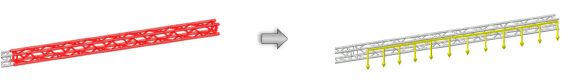
 Inserting a Distributed Load
Mode |
Tool |
Tool set |
|---|---|---|
Distributed Load |
Insert Load
|
Rigging |
To insert a distributed load:
1 Click the tool and mode.
2 Do one of the following:
• To use a saved set of load properties, click Load Settings on the Tool bar and select the load set.
• If not using a saved load set, specify the Load Category; select either Distributed Weight or Total Weight mode and enter the load’s Weight. If entering the distributed weight, enter values with a slash between the weight and the distance (500/10 indicates 500 pounds per 10 feet of length, for example).
3 Move the mouse to the structural element where the distributed load is to be hung.
Valid connecting structures are highlighted.
4 Click to set the load object’s start point.
5 Click to set the end of the segment and the beginning of the next. Continue drawing segments in this manner until the load object is complete. Double-click to finish creating the load object. The distributed load polyline cannot extend beyond the structural element.
The distributed load is placed at the centerline of the structural element.
In Top/Plan view, the distributed load label displays. It can be moved by clicking and dragging the label control point.

The distributed load properties can be edited from the Object Info palette.
► Clique para exibir/ocultar parâmetros.
Command |
Path |
|---|---|
Add Distributed Load at Selection |
Braceworks |
The Insert Distributed Load at Selection command is available for Vectorworks Spotlight software but is not present in the Spotlight workspace. It can be added to the Spotlight workspace (see Customizing Workspaces).
If the length of a distributed load is not critical, a distributed load can be added automatically to the structural elements in the drawing.
To add a distributed load automatically:
1 Select the structural element where the distributed load will be placed. When more than one structure is selected, a distributed load is placed on each one.
Select the system to easily select more than one structural element, and automatically add the same load to each.
2 Select the command.
The Load Settings dialog box opens, for Creating and Selecting Load Sets. Select a load set, or enter load parameters and select the <Active Settings> set.
A distributed load is placed along the length of each structural element.
~~~~~~~~~~~~~~~~~~~~~~~~~
 Resetting
Braceworks IDs
Resetting
Braceworks IDsCommand |
Path |
|---|---|
Reset Braceworks IDs |
Braceworks |
Braceworks requires unique IDs for its structural calculations. The Reset Braceworks IDs command ensures that the identifiers are unique, resetting them for all trusses, straight trusses, curved trusses, lighting pipe objects, and any objects with a weight or load (such as lighting devices, video screens, and so on). Any manually set IDs will be reset by this command.
To reset the ID of all Braceworks-related objects:
Select the command. The IDs are automatically reassigned.
 Checking Loads and Workloads
Command |
Path |
|---|---|
Load Overview |
Braceworks |
The Load Overview command is available for Vectorworks Spotlight software but is not present in the Spotlight workspace. It can be added to the Spotlight workspace (see Customizing Workspaces).
The load overview dialog box provides information about all the loads that participate in structural calculations. While Braceworks is required to perform the calculations, Spotlight users can also take advantage of the load information.
Selecting different loads with the filters on the summary tab adjusts the total load values that participate in calculations, to study the effects of various loads on the calculations.
To view the load information for the file:
1 Select the command.
The Load Overview dialog box opens. Three tabs provide information about the loads in the drawing.
2 Click the Load Summary tab to view summary data about the loads and load categories. The loads in the list participate in calculations (Braceworks required).
► Clique para exibir/ocultar parâmetros.
3 Click the Load Details tab to see detailed information about all of the loads in the drawing (each individual load that is summed by rows on the Load Summary tab). The filters on this tab only apply to the current tab.
Double-click on a row item to select and center the item in the drawing.
The last column indicates whether an error or problem occurred related to the item (for example, its weight is 0 (zero) or the load is not attached to the system). Rows with errors display in red.
► Clique para exibir/ocultar parâmetros.
4 Click the Load Combinations tab to create specific combinations of loads, which can then be used to filter the loads on the other two tabs. A multiplication factor can be applied to various load combinations. Managing Load Combinations describes how to create and set load combinations.
► Clique para exibir/ocultar parâmetros.
5 Apply load combinations to the Load Details or Load Summary tabs by selecting the combination name from the Calculation list. The combination can be used to filter by load and to apply multiplication factors to loads.
The loads listed on the Load Summary tab participate in Braceworks calculations.
~~~~~~~~~~~~~~~~~~~~~~~~~
 Managing Load
Combinations
Managing Load
CombinationsCommand |
Path |
|---|---|
Load Overview |
Braceworks |
The Load Overview command is available for Vectorworks Spotlight software but is not present in the Spotlight workspace. It can be added to the Spotlight workspace (see Customizing Workspaces).
Load combinations serve two purposes; they can be used as a filter in the Load Overview dialog box to display and select (or exclude) specific load types. A multiplication factor can be specified for the items in the combination, increasing their importance in calculations, for safety or other reasons. Load combinations are created based on either layer or class names.
To create and specify a load combination:
1 Select the command.
The Load Overview dialog box opens.
2 Click the Load Combinations tab.
3 Select whether the combination will be layer or class based, and then click Manage.
The Manage Load Combinations dialog box opens.
► Clique para exibir/ocultar parâmetros.
4 Click New.
The Load Combination Properties dialog box opens.
5 Enter the name of the load combination and, optionally, provide a description.
6 Click OK to return to the Manage Load Combinations dialog box.
7 Click OK to return to the Load Combinations tab.
8 The classes or layers display in the table on the right, along with columns showing the current multiplication factors for each load combination.
Click the Hierarchical Display Mode button to toggle the hierarchical display of classes.
9 To use the load combination for filtering purposes only, leave all multiplication factors at 1. To change a multiplication factor, double-click in one of the cells of the table. (Several cells can be selected at once for editing.)
The Load Combination dialog box opens. Specify the multiplication factor.
► Clique para exibir/ocultar parâmetros.
10 Click OK to return to the Load Combinations tab.
11 On the Load Summary and or Load Details tab, select the Load combination from the Calculation list.
Depending on the class or layer of the object, the weight of the object is multiplied by the specified factor for the class or layer and the selected load category.
~~~~~~~~~~~~~~~~~~~~~~~~~
 Performing Load Combination Calculations
Command |
Path |
|---|---|
Calculate Load Combinations |
Braceworks |
When load combinations have been defined by Managing Load Combinations, calculations can be performed just upon the load combinations.
To perform calculations on load combinations:
1 Define the load combinations.
2 Optionally, select the objects to be calculated, or set the visibility of object classes or layers so that only the objects of interest are visible.
3 Select the command.
The Settings dialog box opens.
4 Select the Load Combination from the list. The icon next to the combination indicates whether it is class- or layer-based.
5 Select whether the calculation should occur on all rigging objects in the drawing, or only on a subset of selected or visible objects.
6 Click OK to open the Calculation Overview dialog box.
If the calculation finds issues with the load combination objects, a descriptive label, categorized by color (information, warning, or danger) is inserted in the drawing for each problem object. The problem is listed in the Calculation Overview dialog box.
~~~~~~~~~~~~~~~~~~~~~~~~~
 Checking
the Cross Section Workload
Checking
the Cross Section WorkloadCommand |
Path |
|---|---|
Cross Section Workload |
Braceworks |
The Cross Section Workload command is available for Vectorworks Spotlight software but is not present in the Spotlight workspace. It can be added to the Spotlight workspace (see Customizing Workspaces).
The Cross Section Workload dialog box analyzes the workload and structural properties of the cross sections that participate in calculations. While Braceworks is required for the calculations, Spotlight users can use this command to check the properties of the cross sections in the drawing and check for potential problems.
To check the cross section workload:
1 Select the command.
The Cross Section Workload dialog box opens.
2 Select the Cross Section from the list to view its properties.
► Clique para exibir/ocultar parâmetros.
~~~~~~~~~~~~~~~~~~~~~~~~~
 Performing System Check Calculations
A system check tests the systems in the drawing for solvability and possible failures, but does not calculate forces and deformation. A system check lets you know whether the structures in the drawing may pass when conducting further calculations with the FEA core.
After a system check, information, warning, and danger labels are shown in the drawing, and hoist label fills are colored to reflect their status. Depending on the level of failure, the problems must be fixed to be able to proceed with calculations. Some notifications may refer to data which are failures, but which are deliberate or intentional failures permitted by the selections made in Braceworks preferences (Braceworks required).
Command |
Path |
|---|---|
System Check Selected |
Braceworks |
The System Check Selected command is available for Vectorworks Spotlight software but is not present in the Spotlight workspace. It can be added to the Spotlight workspace (see Customizing Workspaces).
To check selected objects:
1 Select the objects to check. Only the selected objects are considered when running the check.
2 Select the command.
The system check runs on the selected objects, and the Calculation Overview dialog box opens.
If the system check finds issues with the selected objects, a descriptive label, categorized by color (information, warning, or danger) is inserted in the drawing for each problem object. The problem is listed in the Calculation Overview dialog box.
3 Click OK. If no problems are found and the system is considered solvable, proceed to checking all objects.
Command |
Path |
|---|---|
System Check All Objects |
Braceworks |
The System Check All Objects command is available for Vectorworks Spotlight software but is not present in the Spotlight workspace. It can be added to the Spotlight workspace (see Customizing Workspaces).
To check all objects:
1 Select the command.
The system check runs on the Braceworks system objects, and the Calculation Overview dialog box opens. If the system check finds issues with the objects, a descriptive label, categorized by color (information, warning, or danger) is inserted in the drawing for each problem object. The problem is listed in the Calculation Overview dialog box.
2 Click OK. If no problems are found and the system is considered solvable, proceed to Performing Calculations (Braceworks required).
~~~~~~~~~~~~~~~~~~~~~~~~~
 Calculation
Overview
Calculation
OverviewCommand |
Path |
|---|---|
Calculation Overview |
Braceworks |
The Calculation Overview dialog box displays the results of the latest calculation or system check. It opens as the result of calculation and system check commands, but it can also be displayed at any time.
To view the calculation overview:
1 Select the command.
The Calculation Overview dialog box opens.
► Click to show/hide the parameters
~~~~~~~~~~~~~~~~~~~~~~~~~
 Displaying and Correcting Errors
When system check or calculation commands are executed, issues with the drawing are listed in the Calculation Overview dialog box, and labels identifying each issue are automatically placed in the drawing. Information, warning, and danger labels are shown in the drawing. Depending on the failure level, an error must be fixed to proceed with calculations. Some notifications only refer to data which are failures, but deliberate or intentional failures.

After a calculation, reaction forces are written to hoists, and hoist labels are colored according to the workload.

Errors may need to be resolved for the calculations to proceed or for them to be considered useful.
Error |
Description/Possible Resolution |
|---|---|
The static system is not supported |
A set of connected trusses must be supported by hoists or truss crosses. Trusses and connected trusses that make a straight line must have at least two supports, and if they include a corner or a curve, they must have three supports. |
Two trusses intersect in the same plane |
Two trusses cannot intersect and occupy the same space |
The loading point is not attached |
Attach the load to the system |
The load is not connected |
Attach the load to a structural element |
The load has no weight |
Assign a weight to the load |
The rope is slack |
The chain is under too much pressure; the rope or chain will not participate in calculations (in the Braceworks Preferences, Second order analysis is selected) |
The set of connected trusses has no support |
Support the trusses with hoists |
Different cross section |
Two rigging items, such as a truss and a pipe, have two different cross sections and cannot be connected to each other for this reason |
Insufficient RAM to calculate the static system |
The complexity of the system exceeds the memory available on your computer |
The static system could not be calculated |
A critical error is preventing calculations |
The corner truss is not connected |
Connect the corner truss to the truss system |
Chain is under pressure; calculation has failed |
The pressure on the chain exceeded its capacity; fix this critical error to allow calculations to proceed (or select Second order analysis in the Braceworks Preferences to exclude such failures from calculations) |
The static system is not supported |
Support the trusses with hoists |
The drop is not connected |
Connect the hoist to the truss system |
Truss cross is insufficient; calculation has failed |
The force or tension on the truss cross exceeded its capacity; fix this critical error to allow calculations to proceed (or select Second order analysis in the Braceworks Preferences to exclude such failures from calculations) |
Truss cross is under pressure |
The truss cross is under too much force or tension; the truss cross will not participate in calculations (in the Braceworks Preferences, Second order analysis is selected) |
The calculations do not result in adequate supports; the static system is not supported |
The system requires additional hoists as supports |
The ID is already in use |
Hoists with duplicate IDs have been detected; each hoist should have a unique ID for reports and calculations |
Static systems interdependent. No drop compensation possible. |
The hoist cannot be shortened or lengthened due to geometric restrictions created by other structural elements |
Geometry resolution is too low |
Decrease the Geometry Accuracy value in the Braceworks Preferences |
Two structural elements cannot cross in the same plane |
Two trusses cannot intersect and occupy the same space |
Virtual FEM support gets load |
The truss is not balanced properly, and one of the supports is being pushed up because of this |
Duplicated hoist |
Duplicate hoists in same location; remove one of the hoists |
The point load cannot be assigned to two structural elements |
A point load can only be attached to one structural member; move the point load so that it is only attached to one |
The line load cannot be assigned to two structural elements |
A distributed load can only be attached to one structural member; move the distributed load so that it is only attached to one |
The suspension point is not attached |
Attach the hoist to a truss system |
Structural elements are not connected |
The structural elements were not connected to create a system; enable Auto Connect mode of the Insert Truss tool and ensure that the two structures are compatible |
Two structural elements cannot occupy the same space |
Two structural elements cannot occupy the same location |
The support is stressed by compressive forces |
The pressure on the hoist is at or has exceeded its limit |
The line load is longer than the structural element |
A line load cannot exceed the length of the structural element to which it is connected |
After correcting errors, re-run the calculations, or select Clear Calculation Results.
~~~~~~~~~~~~~~~~~~~~~~~~~
 Clearing
Calculation Results
Clearing
Calculation ResultsCommand |
Path |
|---|---|
Clear Calculation Results |
Braceworks |
The Clear Calculation Results command is available for Vectorworks Spotlight software but is not present in the Spotlight workspace. It can be added to the Spotlight workspace (see Customizing Workspaces).
The results from the most recently executed calculation (Braceworks required) or system check command are retained and display in the Calculation Overview dialog box. These results can be cleared with the Clear Calculation Results command.
To clear calculation results:
Select the command. All calculation results and any resulting issues are cleared. Any issue labels in the drawing are removed, and any color coding of hoist labels reverts to red.
~~~~~~~~~~~~~~~~~~~~~~~~~
 Performing Calculations
After running system checks on selected portions of the drawing, and then a system check on the entire drawing, and correcting all errors, calculations can be performed using the FEA core.
After a calculation, Influence Lines are created and display on the drawing. Reaction forces are applied to hoists; label fills are colored according to the workload status.
Command |
Path |
|---|---|
• Calculate Selection • Calculate Visible |
Braceworks |
Before calculating all objects, run calculations on a smaller subset of objects. This allows you to detect problems before calculating everything in the drawing.
To run calculations on selected or visible objects:
1 Select the objects to be calculated, or set the visibility of object classes or layers so that only the objects of interest are visible.
2 Select the appropriate command. The Calculation Overview dialog box opens, listing any issues and providing calculation data.
Command |
Path |
|---|---|
Calculate All Objects |
Braceworks |
When the drawing is complete and errors have been addressed, run the final calculation on all rigging objects in the file.
To run calculations on all objects:
Select the command. The Calculation Overview dialog box opens, listing any issues and providing calculation data.
~~~~~~~~~~~~~~~~~~~~~~~~~
 Influence Lines
After a calculation, influence lines are placed on the structural elements of a drawing to graphically represent and assist with understanding the results. The influence lines represent the reactions and forces (shear, bending, torsion, and deflection) applied to the structural element by the loads hanging from the structure, and show where the force or reaction exerts its maximum effect upon the structure.
The influence lines are color-coded (by class) to represent various forces:
• Deflection (dx, dy, dz, du): purple
• Force (normal (Nx) and shear Vy, Vz)): green
• Torsional moment force (Mt): blue
• Bending moment force (Mby, Mbz): red
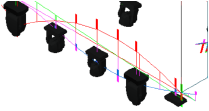
The class names are determined by the settings on the Classes tab of the Braceworks Preferences.
The Object Info palette of a selected influence line displays its specific deflection, force, torsion, and bending moment values. Forces applied to the tubing and braces of the structural element are also displayed.
In a complex drawing, you may wish to deselect Show Calculation Points, to make the drawing easier to interpret. Text with the relevant maximum value is placed at the top of the influence line; adjust this text with the Text Size parameter.
The heat map display for trusses can be adjusted in the Braceworks Preferences to show the influence line values for a selected force (normal, shear, torsional moment, or bending moment).
Command |
Path |
|---|---|
Scale Influence Lines |
Braceworks |
The influence lines in the drawing can be scaled to better view the maximum response of the reactions and forces exerted upon the structural elements.
Deselect Automatic Scaling in the Braceworks preferences for optimal results when scaling influence lines manually.
To scale the influence lines:
1 Select the command.
The Scaling Influence Lines dialog box opens. Each type of influence line is listed, with controls to change its scale by zooming or logarithmically.
2 The current scale factor of each influence line is displayed. Click + to enlarge the influence line display, or - to reduce it. Alternatively, drag the logarithmic slider to the right to enlarge, or left to decrease the influence line scale factor.
~~~~~~~~~~~~~~~~~~~~~~~~~
 Generating and Exporting Calculation
Reports
Generating and Exporting Calculation
ReportsCompleted calculations can be shared with colleagues, clients, and structural engineers by sending the results to a customized report in a PDF file, or exporting them to DSTV format.
Command |
Path |
|---|---|
Create Calculation Report |
Braceworks |
A comprehensive report of the calculations can be generated as a PDF file.
To create a calculation report:
1 Select the command.
The Create PDF report dialog box opens. Cycle through each pane in order with the <Back and Forward> buttons to create and customize a complete report.
The system must be solvable to be able to create a report.
► Clique para exibir/ocultar parâmetros.
2 When all items in each pane have been addressed, click Create PDF to create the report. Provide a name and location to save the file.
~~~~~~~~~~~~~~~~~~~~~~~~~
 Exporting
Calculation Results
Exporting
Calculation ResultsCommand |
Path |
|---|---|
Export DSTV |
Braceworks |
To export the results of the last calculation to an .stp file in DSTV format:
1 Select the command.
The Settings dialog box opens.
2 From the Load Combination list, select <No Load Combination> or choose a load combination. The icon next to the combination indicates whether it is class- or layer-based.
3 Select whether the exported results should include all rigging objects in the drawing, or only a subset of selected or visible objects.
4 Click OK.
Specify a file name and location for saving the file, and click Save.
~~~~~~~~~~~~~~~~~~~~~~~~~


