Cable
ToolsCable
Tools
Cable
ToolsCable
ToolsThe cable tools in the Vectorworks Spotlight program allow entertainment industry professionals to plan cable runs, estimate required parts, and prepare the number and types of cables required for a site. A suite of tools and commands assist you with creating the diagrams and paperwork needed for electrical cabling work.
|
Clique aqui para uma dica em vídeo sobre este topico (rquer acesso à internet). |
~~~~~~~~~~~~~~~~~~~~~~~~~
 Setting Preferences
Set up cable preference settings prior to creating cables.
Command |
Path |
|---|---|
Cable Preferences |
Spotlight > Cables |
The Cable Preferences command sets default cable lengths and offset distances.
To set up cable preferences:
Select the command. The Cable Preferences dialog box opens.
► Clique para exibir/ocultar parâmetros.
Command |
Path |
|---|---|
Circuit Assign Preferences |
Spotlight > Cables |
By default, the Assign Multicable Circuits command assumes that the multicable circuit information is to be assigned to lighting devices. However, there are other situations where multicable information needs to be assigned to speakers or other types of stage objects. The Circuit Assign Preference command determines how to assign values to objects that are not lighting devices.
To set up multicable circuit preferences:
Select the command. The Circuit Assign Preferences dialog box opens.
► Clique para exibir/ocultar parâmetros.
Command |
Path |
|---|---|
Multicable Jumper Preferences |
Spotlight > Cables |
The Multicable Jumper Preferences command determines default placement options when placing multicables with jumper cables.
To set up multicable jumper preferences:
Select the command. The Multicable Jumper Preferences dialog box opens.
► Clique para exibir/ocultar parâmetros.
~~~~~~~~~~~~~~~~~~~~~~~~~
 Inserting Feeder Cables
Mode |
Tool |
Tool set |
|---|---|---|
Modes for the Polyline Tool |
Feeder Cable
|
Lighting |
On a show site, feeder cables are usually set up first. These carry power from the building service or generator to the distribution systems that power the lights, motors, amplifier racks (power distribution racks and dimmer racks), video projectors, and more.
To insert a feeder cable:
1 Click the tool and mode.
2 Click to place the start of the cable, and draw the cable polyline, clicking at each vertex. Double-click to finish drawing the cable.
The first time you use the tool in a file, a properties dialog box opens. Set the default properties.

After placement, the cable path can be adjusted with the Reshape tool. The properties can be edited from the Object Info palette.
► Clique para exibir/ocultar parâmetros.
~~~~~~~~~~~~~~~~~~~~~~~~~
 Inserting Multicables
Mode |
Tool |
Tool set |
|---|---|---|
Modes for the Polyline Tool |
Multicable
|
Lighting |
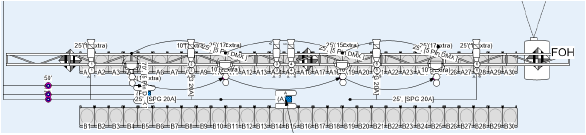
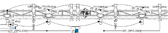
Multi-circuit cables, also known as multicables, carry power from power distribution racks and dimmer racks to the lighting instruments, projectors, and other devices. Multicables include break in and break out parts, which attach to the cable and allow power to enter the multicable and to be distributed from the cable.
Some of the multicable parameters that are tedious to manually assign can be automatically assigned, as described in Assigning Circuit Information and Placing Break Out Labels.
Multicable break outs have special labels; entering some of the multicable and break out information can be accomplished from the Object Info palette of the associated label. See Placing Break Out Labels.
To insert a multicable:
1 Click the tool and mode.
2 Click to place the start of the cable, and draw the cable polyline, clicking at each vertex. Double-click to finish drawing the cable.
The first time you use the tool in a file, a properties dialog box opens. Set the default properties.

After placement, the cable path can be adjusted with the Reshape tool. The properties can be edited from the Object Info palette.
► Clique para exibir/ocultar parâmetros.
~~~~~~~~~~~~~~~~~~~~~~~~~
 Inserting
Jumper Cables
Inserting
Jumper CablesMode |
Tool |
Tool set |
|---|---|---|
Modes for the Polyline Tool |
Jumper Cable
|
Lighting |
These break out cables connect the multicable to the devices, breaking out the power into individual circuits. Single circuit cables also go from the rack or the break out cable to the device.
Jumper cables can be automatically added to the drawing; see Creating a Jumper Cable Chain.
To insert a jumper cable:
1 Click the tool and mode.
2 Click to place the start of the cable, and draw the cable polyline, clicking at each vertex. Double-click to finish drawing the cable.
The first time you use the tool in a file, a properties dialog box opens. Set the default properties.

After placement, the cable path can be adjusted with the Reshape tool. The properties can be edited from the Object Info palette.
► Clique para exibir/ocultar parâmetros.
~~~~~~~~~~~~~~~~~~~~~~~~~
 Inserting
Data Cables
Inserting
Data CablesMode |
Tool |
Tool set |
|---|---|---|
Modes for the Polyline Tool |
Data Cable
|
Lighting |
Data cables carry data signals, such as network, DMX, and audio information, from controllers to the various devices, or from device to device.
Data cables can be automatically added to the drawing; see Creating a Data Cable Chain.
To insert a data cable:
1 Click the tool and mode.
2 Click to place the start of the cable, and draw the cable polyline, clicking at each vertex. Double-click to finish drawing the cable.
The first time you use the tool in a file, a properties dialog box opens. Set the default properties.

After placement, the cable path can be adjusted with the Reshape tool. The properties can be edited from the Object Info palette.
► Clique para exibir/ocultar parâmetros.
~~~~~~~~~~~~~~~~~~~~~~~~~
 Creating Cable Chains
Instead of manually placing data cables or jumper cables on a complex light plot with hundreds or even thousands of lights, the Vectorworks Spotlight software can automatically place the cables in a chain between lighting devices, speakers, projectors, or any symbol.
The Setting Cable Preferences dialog box controls which side to place the cables, and the offset distance between the cables and the lighting devices.
Command |
Path |
|---|---|
Make Jumper Cable Chain |
Spotlight > Cables |
To create a jumper cable chain:
1 Select the command.
The Make Jumper Cable Chain dialog box opens.
► Clique para exibir/ocultar parâmetros.
2 Click on each object to be linked.
3 Click in a blank area of the drawing to finish creating the jumper cable chain.

Command |
Path |
|---|---|
Make Data Cable Chain |
Spotlight > Cables |
To create a data cable chain:
1 Select the command.
2 As you move the cursor over a valid object, such as a lighting device, the object is highlighted; click on the first object in the chain.
3 Click on each object to be linked.
4 Click in a blank area of the drawing to finish creating the data cable chain.

~~~~~~~~~~~~~~~~~~~~~~~~~
 Assigning Multicable Information
Multicable circuiting and labels can be automatically assigned to the connected fixtures on the light plot. If the multicables are feeding power to devices other than lighting devices, first select the Circuit Assign Preference command to determine where to send the circuit information from the break out cables; see Setting Circuit Data Assignment Preferences.
Assign the cables with ID labels with the Spotlight Numbering command; see Numbering Light Plot Objects for more information.
Command |
Path |
|---|---|
Assign Multicable Circuits |
Spotlight > Cables |
To automatically assign multicable circuit information to associated lighting devices (or other equipment):
1 Select the multicable object. The multicable needs to have a Cable Run ID assigned to it.
2 Select the command.
The Assign Multicable Circuits dialog box opens. Enter the starting number of the first break out cable. If desired, select the option to remove the break out circuit number for break out cables that are not assigned to an object. For example, if the break out consists of six cables, but only five devices are assigned, the unused break out cable has its circuit data removed, since it is not in use.
3 Click OK.
4 A VectorScript window opens, providing helpful information as you assign the circuit data to the devices.
• The circuit name and circuit number to be assigned to the next lighting device are displayed. Click lighting devices sequentially to assign the displayed circuit information to the next lighting device.
• Press the Shift key while clicking on the next lighting device to skip a circuit number.
• Press the Ctrl (Windows) or Command (Mac) key while clicking to gang the next device to the previous one. A symbol is placed on the drawing indicating the location of the ganged devices.

• Press Shift+Ctrl (Windows) or Shift+Command (Mac) while clicking on the next device to specify the circuit number. The Enter Value dialog box opens; enter the circuit number.
5 Continue assigning circuit information until the number of break out circuits has been reached. Click in a blank area of the drawing to finish.
The Circuit Name and Circuit Number parameters of the lighting devices have been automatically assigned based on the multicable break out circuits.
Command |
Path |
|---|---|
Place Break Out Labels |
Spotlight > Cables |
Multicables can be automatically labeled with break out information that shows multicable circuiting information. A variety of labels are available by default; custom labels can also be created.
To label multicables with break out information:
1 If adding labels to specific multicables, select the multicable objects. To add labels to all multicables, do not select any multicables.
2 Select the command.
If no multicables are selected, confirm that you want to label all multicables. The Place Break Out Labels dialog box opens.
► Clique para exibir/ocultar parâmetros.
Right-click on the break out label and select Select Multicable from the context menu to select the multicable associated with the label.
The break out label properties can be edited from the Object Info palette. Changes made to the label parameters are reflected in the parameters of the associated multicable object.
► Clique para exibir/ocultar parâmetros.
~~~~~~~~~~~~~~~~~~~~~~~~~
 Creating
Custom Break Out Labels
Creating
Custom Break Out LabelsIn addition to the provided default break out labels, you can create your own labels.
To create a custom break out label:
1 Create a 2D symbol definition with the desired appearance and text.
2 Attach the Break Out Marker Record format to the symbol definition.
3 Link the text fields to the record fields as described in Linking Text to Record Formats.
4 When selecting a break out label from the Use Break Out Label Type or Use Symbol list, the list includes any symbol definitions present in the drawing with the Break Out Marker Record attached.
~~~~~~~~~~~~~~~~~~~~~~~~~
 Marking Cable Measurements
To assist with creating cable layouts on site, distance measurements can be added to the drawing.
Command |
Path |
|---|---|
Mark Specific Distance |
Spotlight > Cables |
A specific distance can be marked from the start of any cable by entering a distance value.
To mark a specific distance on a cable:
1 Select the cable.
2 Select the command.
The Enter Value dialog box opens.
3 Enter the distance value from the start of the cable to where the marker should be placed, and click OK.
4 If the cable travels vertically, confirm that you wish to include the vertical distance in the measurement. Then enter the vertical distance in the Enter Value dialog box.
The distance marker is placed on the drawing.

Command |
Path |
|---|---|
Get Distance Start to Click |
Spotlight > Cables |
A label can be placed to mark the specific distance from the start of the cable to a point clicked on the cable.
To mark a clicked distance on a cable:
1 Select the command.
2 Click on the cable at the point where the measurement marker should be placed.
The Enter Value dialog box opens.
3 If the cable travels vertically, enter the vertical distance; otherwise enter 0 (zero).
The distance marker is placed on the drawing.

~~~~~~~~~~~~~~~~~~~~~~~~~
 Selecting, Refreshing, and Converting
Cables
Selecting, Refreshing, and Converting
CablesSeveral cable commands help with quickly selecting cables, refreshing cable data, and converting cables from one type of cable to another or creating a cable from a polyline.
Command |
Path |
|---|---|
Select Cables |
Spotlight > Cables |
To easily select cables in the drawing:
Select the command. The Select Cables dialog box opens; set the selection criteria.
► Clique para exibir/ocultar parâmetros.
Command |
Path |
|---|---|
Refresh All Cables |
Spotlight > Cables |
To update all the cables in the drawing with the values from the Object Info palette, resetting the cable data, select the command. If cable lengths changed, so that a shorter or longer standard cable length is now required, an informational alert opens.
Command |
Path |
|---|---|
Convert to Cable |
Spotlight > Cables |
A polyline or polygon can be converted into a cable, or one kind of cable can be converted into a different kind of cable.
To convert to a cable:
1 Select the polyline or polygon, or the cable to be converted.
2 Select the command.
The Convert to Cable dialog box opens; specify the new cable settings.
► Clique para exibir/ocultar parâmetros.
~~~~~~~~~~~~~~~~~~~~~~~~~
 Creating Cable Worksheets
Command |
Path |
|---|---|
Create Cable Worksheet |
Spotlight > Reports |
The Create Cable Worksheet command creates editable worksheets with database rows according to the cable type. For more information about worksheets, see Planilhas.
To create cable worksheets:
1 Select the command.
The Create Cable Worksheets dialog box opens. Select the cable worksheets to create.
2 For each worksheet to be created, click Worksheet Setup.
The Select [Cable type] Fields dialog box opens.
► Clique para exibir/ocultar parâmetros.
3 Cable worksheets can be filtered by layer; only the cables in the selected layer or layers are included in the generated worksheets. Select Filter Cable Display by Layer, and then click Select Layers.
The Select Layers dialog box opens. The layers in the file are listed.
4 Click on the layers with cables to include in worksheets (Shift-click to select multiple layers, up to five).
The worksheet rows are sorted by the unique cable Run ID number. In addition to the selected fields, the cable’s layer information is included. At the bottom of the worksheet, an inventory of cable wire type, length, number of cables required, connectors, adapters, and for multicables, break ins and break outs, is provided.
Because the cable worksheets consist of database rows, edits to the worksheet are applied to the objects in the drawing.
Once the worksheets have been generated, reflect any drawing changes by selecting the Create Cable Worksheet command again and regenerating the worksheets.
~~~~~~~~~~~~~~~~~~~~~~~~~