Os produtos Vectorworks Fundamentals, Landmark e Spotlight oferecem uma ferramenta de Escada Simples que pode ser usada em desenhos que não exijam uma escada complexa. Já os produtos Vectorworks Architect, Landmark e Designer incluem uma ferramenta de Escada, e as configurações podem ser alteradas para que você possa adicionar a ferramenta Escada Simples.
Estas ferramentas permitem construir escadas com geometrias variadas. A escada é um objeto híbrido que oferece controle sobre a aparência 2D, bem como o componente 3D, para apresentações de planta e de desenho. A ferramenta Escada traz diversas opões, detalhes e configurações, e realiza várias tarefas de escadaria automaticamente.
A ferramenta Escada oferece um conjunto de configurações comuns (reta, em L, em U, em O e circular). Isto permite a criação de estilos a partir dos conjuntos de grupos controladores de parâmetros da geometria e dos atributos de exibição, que podem ser salvos e reutilizados em outras escadas. A escada pode ser configurada para determinar a sua própria altura de piso a piso com base nas camadas conectadas pela escada, e pode tirar proveito de um projeto definido com andares. A escada pode ter representações gráficas separadas para o andar superior e o andar inferior. Com isto você não precisa desenhar escadas em duas camadas diferentes para representar a mesma escada, e nem editá-las separadamente. As opções de quebra de escada podem ser configuradas de forma diferente em cada camada, permitindo que você obtenha a aparência desejada na vista Topo/Plano. Toda a configuração da escada pode ser salva em um símbolo para ser reutilizada ou compartilhada com outros usuários, criando uma biblioteca de padrões de escadas. Os parâmetros também podem ser copiados de uma escada para outra.Apesar da variação geométrica da escada ser restrita, o nível de controle sobre os atributos 2D e 3D é grande. As escadas podem ser criadas como objetos somente 2D ou objetos híbridos.
~~~~~~~~~~~~~~~~~~~~~~~~~
Um objeto de escada simples é disponibilizado para adicionar uma representação básica de uma escada em um desenho. Produtos Design Series contém duas ferramentas adicionais de escadas quando o projeto requer escadas complexas, detalhadas. Veja “Inserindo Escadas” on page 631).

Para inserir uma escada simples:
1. Clique na ferramenta Escada Simples a partir do conjunto de ferramentas apropriado:
• Fundamentals: conjunto de ferramentas de Paredes
• Landmark e Spotlight: conjunto de ferramentas Building Shell
2. Clique para posicionar a Escada Simples no desenho, e clique novamente para definir a rotação da escada. Se esta for a primeira vez que estiver inserindo uma escada no desenho, a janela de diálogo de propriedades da escada abrirá. Estes parâmetros serão então aplicados em todas as próximas escadas aplicadas no desenho.
Os parâmetros de escada podem ser editados na Paleta info de Objetos.
Clique para mostrar / ocultar os parâmetros.
 Creating a Stair
The Stair tool is available in the Vectorworks Architect, Landmark, and Designer workspaces. If the stair will have a lower layer and upper layer representation, or if its total rise will be defined by layer or story elements, it should be inserted on the layer representing the lower of the two floors it connects.

To insert a stair:
1. Click the Stair tool from the Building Shell tool set.
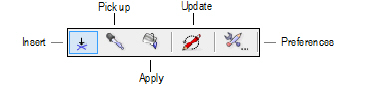
Five modes are available.
Mode |
Description |
|---|---|
Insert |
Inserts a stair with the parameters specified in Preferences |
Pick up |
Picks up selected attributes from a stair to be transferred to another stair; attributes are selected in the stair preferences |
Apply |
Transfers selected attributes from one stair to another; attributes are selected in the stair preferences and picked up in Pick up mode. |
Update |
Updates all stairs in the drawing, which is necessary when layer scale has changed and a change to the stair’s schematic representation is also required |
Preferences |
Opens the Stair Settings dialog box, to set default stair parameters |
2. Select Insert mode and then click Preferences from the Tool bar before placing the stair to set the default stair parameters. Click OK to set the stair parameters and close the Stair Settings dialog box.
Alternatively, insert the default stair and then click Settings from the Object Info palette, or simply double-click on an existing stair, to set the stair parameters.
3. When the stair configuration parameters on each tab are set, consider whether to save the stair as a symbol.
If the same customized stair is to be used numerous times in a drawing, or will be used in another drawing or by another designer, this eliminates the need to repeatedly apply parameters, maximizes memory efficiency, and allows global editing of symbols. See “Creating New Symbols” on page 235.
If you don’t wish to create a symbol, the stair attributes can easily be transferred.
4. Click in the drawing to insert the stair. Click again to set the stair’s rotation.
To edit stair parameters for a placed stair, click Settings from the Object Info palette, double-click the stair to open the Stair Settings dialog box, or right-click (Windows) or Ctrl-click (Mac) on a stair and select Edit from the context menu. Depending on the stair settings, certain parameters are available directly from the Object Info palette.
Each tab of the stair parameters is described in the following sections. As the parameters are defined, the preview dynamically displays the stair appearance.
• “Stair Settings: General Tab” on page 634
• “Stair Settings: Geometry Tab” on page 636
• “Stair Settings: 2D Graphics Tab” on page 642
• “Stair Settings: Construction Tab” on page 645
• “Stair Settings: Railings Tab” on page 648
• “Stair Settings: Graphic Attributes Tab” on page 652
• “Transferring Stair Properties” on page 657
~~~~~~~~~~~~~~~~~~~~~~~~~
 Stair
Settings: General Tab
Stair
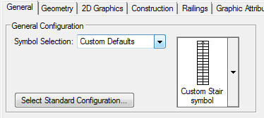
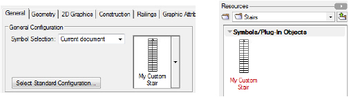
Settings: General Tab1. Click the General tab to set the stair configuration.
Select a predefined configuration as the basis for the new stair. The general configuration can be based on either pre-defined default content symbols, custom default files in the user folder, a saved symbol in the current file, or by selecting a typical stair configuration.
• From the Symbol Selection list, select an initial stair configuration from the current file, custom defaults, or from the standard configurations. Once a selection has been made, a symbol selection list allows the symbol or predefined symbol to be selected from the file, custom, or default content (see “Resource Libraries” on page 215).
• Click Select Standard Configuration to select an initial stair configuration that most closely matches the type of stair to create. The Select a Stair Configuration dialog box opens; select one of the configurations. If there are any current stair parameters that should be saved and transferred to the new stair, select the category or categories from Transfer settings from current stair.
When the stair configuration has been selected, the available parameters on the tabs change to reflect the selection.
2. Once the initial configuration has been selected, change parameters as necessary to define the stair.
Minimum and maximum value ranges can be set for the stair angle, tread depth, riser height, and step length.
Click to show/hide the parameters.
3. If you switch to another stair configuration after making parameter changes on any tab, the New Stair dialog box opens.
Switching to a new configuration loses any parameter settings that have already been made. The settings from the current stair configuration can be transferred to the new stair if needed. Select the settings to transfer, or click All to select all settings and None to deselect all the settings.
~~~~~~~~~~~~~~~~~~~~~~~~~
 Stair
Settings: Geometry Tab
Stair
Settings: Geometry Tab1. Click the Geometry tab to set both basic and detailed stair geometry based on the configuration selected on the General tab. The geometry parameters automatically influence each other; entering a few desired parameters causes the remaining parameters to adjust accordingly.
The diagrams next to each parameter indicate the relevant area of the stair.
Click to show/hide the parameters.
2. If setting the stair Total Rise by layer elevation instead of by a specific value, the height of the stair can be constrained by layer or story elements at its top and bottom boundaries; the lower floor and upper floor indicate the two stories the stair connects. Adjusting a bounding element causes the height of the stair to automatically change accordingly.
Select By Layer Elevation; the Total Rise by Layer Elevations dialog box opens.
Click to show/hide the parameters.
Click OK to set the stair total rise.
3. The Preview contains two preview graphics.
• The lower preview graphic displays a detailed section/elevation view of the treads and risers, and indicates the current rise angle.
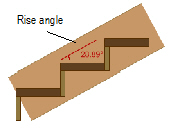
• The upper preview graphic displays the Top/Plan view and is interactive.
• Click on an upper or lower tread to set the oblique tread parameters for the highlighted treads.
• L- and U-Stairs have clickable red areas at the corner of the landing. Click each area to set corner parameters for the inside and outside corners of the landing. The Stair Landing Corners dialog box opens. For configurations that allow angles other than 90 degrees, enter the desired Angle between flights; the corner style parameters update automatically. For each corner, set the Corner Style to the desired angle, or round the corner by specifying a chamfer or fillet value.
• For Double-U and Triple-L configurations, some parts of the stair may overlap in the Top/Plan preview, making it difficult to select and edit the intended corner parameters. Before clicking the red areas to set corner parameters for these configurations, select whether the preview displays the Upper part of stair or Lower part of stair.
• For fixed angle winder stair configurations, click on the stair winder to set the winder parameters. The Winder Parameters dialog box opens. Specify the number of treads for the winder section of the stair, and select whether the winder tread depths should match the tread depths for the straight parts of the stair. If maintaining a constant tread depth is desired, the minimum winder tread depth may need to be adjusted to prevent errors.
The Geometry tab allows values to be locked, which forces other parameters to recalculate while maintaining appropriate calculated values for the stair. Occasionally, a invalid entry is attempted, which generates an error due to other locked values. An alert dialog box notifies you of the error and offers several possible options to avoid it.
Situations which can generate an alert include:
• The total rise calculation is based on multiplying the number of risers by the riser height, and therefore cannot be edited without changing one of the values. Similarly, the number of risers or riser height cannot be edited when the total rise is locked.
Parameter to be edited |
Locked |
Unlocked |
Resolution |
|---|---|---|---|
Total rise |
Riser Height |
Num. of Risers |
Change the riser height or the total rise and number of risers as suggested, or return to previous values |
Total rise |
Num. of Risers |
Riser Height |
Modify the riser height, or the riser height and the number of risers as suggested, or return to previous values |
Total rise |
Riser Height and Num. of Risers |
N/A |
Change the riser height and/or the number of risers as suggested, or return to previous values |
Riser height |
Total rise |
N/A |
Modify the total rise, or the riser height and number of risers as suggested, or return to previous values |
Number of risers |
Total rise |
N/A |
Change the total rise, or the riser height/step length, or the riser height and number of risers as suggested, or return to previous values |
• The total rise of the stair and the stair length (or sweep angle, for circular stairs) impact other values such as tread depth, riser height, and the number of risers. When the length/sweep angle is locked, it may become impossible to obtain valid entries for the other parameters. Since the stair length or sweep angle is a multiple of the tread depth, one cannot be edited when the other is locked.
Parameter to be edited |
Locked |
Resolution |
|---|---|---|
Total rise |
Length or Sweep Angle |
Change the number of risers and step length, or unlock the length/sweep angle as suggested, or return to previous values |
Tread depth |
Length or Sweep Angle |
Modify the length/sweep angle, and/or change the number of risers and the tread depth as suggested, or return to previous values |
Length or Sweep Angle |
Tread Depth |
Change the tread depth, and/or the number of risers, or change the risers and length/sweep angle as suggested, or return to previous values |
~~~~~~~~~~~~~~~~~~~~~~~~~
 Stair
Settings: 2D Graphics Tab
Stair
Settings: 2D Graphics TabThe remaining four stair configuration tabs have a method of saving and recalling each tab’s settings or style. The settings on the tab can be saved as a set and then loaded, replacing the current tab parameters.
1. Click the 2D Graphics tab to set the stair’s 2D appearance on lower and, if desired, upper floors. The lower floor is always the floor where the stair has been placed. Selecting display options for the upper floor is optional; the upper floor representation is usually on another layer, and can be specifically selected here. These parameters apply only to the Top/Plan view, and do not affect the 3D appearance of the stair.
Click to show/hide the parameters.
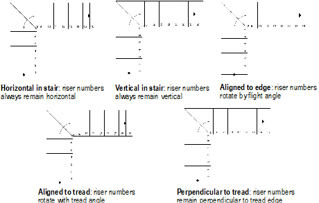
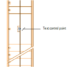
2. Click Stair Data for the lower, and optionally, the upper floor, to set the display of the 2D stair information text.
The Stair Data Settings dialog box opens. The stair configuration determines the number of available run or flight parameters. Stair data text appearance is set on the Graphic Attributes tab.
Click to show/hide the parameters.
The position of the stair run and note text can be adjusted by moving its control point.
3. Click OK to return to the Stair Settings dialog box.
~~~~~~~~~~~~~~~~~~~~~~~~~
 Stair
Settings: Construction Tab
Stair
Settings: Construction TabThe settings on the tab can be saved as a set and then loaded, replacing the current tab parameters.
Click the Construction tab to specify stair construction parameters. The parameters displayed depend on the selected construction configuration.
Click to show/hide the parameters.
~~~~~~~~~~~~~~~~~~~~~~~~~
 Stair
Settings: Railings Tab
Stair
Settings: Railings TabThe settings on the tab can be saved as a set and then loaded, replacing the current tab parameters.
Click the Railings tab to set the stair’s handrail and guardrail parameters. The Railings tab is divided into three panes. On the left, the handrail and guardrail categories display, along with each current setting for the left, right, or both sides of the stair. Handrail and guardrail parameters are set separately. Click a disclosure arrow to reveal handrail or guardrail parameter categories. Select a category to edit its parameter settings in the middle pane. On the right, three previews display the railing cross-section, top/plan stair view, and isometric stair view.
Click to show/hide the parameters.
~~~~~~~~~~~~~~~~~~~~~~~~~
 Stair
Settings: Graphic Attributes Tab
Stair
Settings: Graphic Attributes TabThe settings on the tab can be saved as a set and then loaded, replacing the current tab parameters.
1. Click the Graphic Attributes to specify the appearance of stair components.
Click to show/hide the parameters.
2. The graphic attributes of each item is displayed, and can be set by double-clicking on the item’s line.
An attributes dialog box with the name of the item is displayed. See “A Paleta de Atributos” on page 1091 for information on setting attributes.
3. Set the attributes and click OK to return to the Graphic Attributes tab.
~~~~~~~~~~~~~~~~~~~~~~~~~
 Managing
Stair Styles
Managing
Stair StylesIn the Stair Settings dialog box, the 2D Graphics, Construction, Railings, and Graphic Attributes tabs have the option of saving the current tab’s settings as a style that can be recalled later. The stair minimum/maximum settings can also be saved as a style set.
To save tab settings as a style:
1. When the tab parameters have been set, click Save (located in the Styles area at the top left of the tab).
The Save Style dialog box opens.
Click to show/hide the parameters.
2. Click OK to save the style set.
The new style name appears in the Styles list.
To recall a saved style:
Select the style from the Styles list. Any currently set parameters are replaced by those of the saved style set. The Styles list contains saved styles as well as a limited number of default styles.
Styles can be renamed and deleted.
Default styles (located in the application folder) cannot be renamed or deleted.
To manage styles:
1. Click Manage Styles (located in the Styles area at the top left of the tab).
The Styles dialog box opens, listing all currently saved style sets and their saved location.
Click to show/hide the parameters.
2. Click OK to return to the Stair Settings dialog box.
~~~~~~~~~~~~~~~~~~~~~~~~~
 Saving
a Stair as a Symbol
Saving
a Stair as a SymbolThe stair configuration, along with all its parameters, can be saved as a symbol for use again in the current file or in another “library” file. The stair is saved as a red symbol and becomes a plug-in object with pre-set parameters when inserted. See “Symbols” on page 233.
To save the stair as a symbol:
1. From the Stair Settings dialog box, click Save as symbol.
The Save Stair dialog box opens.
Click to show/hide the parameters.
2. Select whether to save the stair symbol in the current file or in a library file.
• To save the symbol in a library file, select Save as template in library file and enter a name for the symbol
• To save the symbol in the current file, select Save as symbol in current document, enter a name for the symbol, and select a symbol folder destination for the symbol by double-clicking on the selected symbol folder name
3. Click OK.
• If the symbol was saved in the user default library, it is available from the General tab’s Symbol Selection list under the Custom Defaults category. Library files can be shared among users.
• If the symbol was saved in the current file, it is available from the General tab’s Symbol Selection list under the Current Document category, and also from the Resource Browser. Symbols can be shared by exporting them from the Resource Browser (see “Exporting Custom Resources” on page 230).
~~~~~~~~~~~~~~~~~~~~~~~~~
 Setting
Minimum and Maximum Values for Stair Geometry Parameters
Setting
Minimum and Maximum Values for Stair Geometry ParametersWhen setting stair parameters, a geometry “envelope” can be set to specify the allowable value ranges for tread depth, riser height, step length, and stair angle. Setting these values can assist with creating proportional stair geometry that complies with standards.
During the initial phases of design, it may be convenient to temporarily disable the minimum/maximum restrictions by deselecting Use Minimum/Maximum Values from the Stair Settings dialog box.
The stair minimum/maximum settings can be saved as a style set and then loaded, replacing the current dialog box parameters.
To set minimum and maximum stair parameter ranges:
1. From the Geometry pane of the Stair Settings dialog box, click Edit.
The Min/Max Settings dialog box opens.
Click to show/hide the parameters.
2. Set the geometry minimum and maximum values and click OK.
~~~~~~~~~~~~~~~~~~~~~~~~~
 Stair
Properties
Stair
PropertiesCertain stair parameters can be edited directly from the Object Info palette, depending on the settings of the selected stair. These parameters display when the Total Rise of the stair is set by Layer Elevation, or the stair has an upper floor representation. All of the stair parameters can be edited by clicking Settings from the Object Info palette.
Click to show/hide the parameters.
~~~~~~~~~~~~~~~~~~~~~~~~~
 Transferring
Stair Properties
Transferring
Stair PropertiesSpecific stair parameters can be transferred from one stair to another.

To transfer stair attributes:
1. Click the Stair tool from the Building Shell tool set and select Pick up mode from the Tool bar.
2. Click Preferences from the Tool bar to set the transfer parameters.
The transfer attributes cannot be accessed when clicking Settings from the Object Info palette.
3. Click the Transfer tab.
Click to show/hide the parameters.
4. Select the attributes to transfer, and select whether the attributes should become Stair tool defaults and/or should also apply to all stairs in the file.
5. Click OK.
6. In Pick up mode, click on the stair with the desired attributes.
The cursor changes to an eyedropper, and the source stair is highlighted in red.
7. Move the cursor to the target stair, and click Apply mode from the Tool bar.
Press the Option (Mac) or Ctrl (Windows) key to switch between the Pick up and Apply modes.
8. Click on the target stair to transfer the selected attributes.
~~~~~~~~~~~~~~~~~~~~~~~~~
 Inserting Escalators
A basic escalator can be inserted, with its height defined automatically from its top and bottom layer boundaries.

To insert an escalator:
1. Select the Escalator tool from the Building Shell tool set.
2. The escalator is a point object; click once to insert the escalator, and then again to set the rotation.
If this is the first time the tool is used in this session, the Escalator Properties dialog box opens. Specify the preferences to use for this tool during this session, and then click OK.
The parameters can be changed in the Object Info palette after insertion.
Click to show/hide the parameters.
 Inserting Ramps
To insert a ramp:
1. Select the Ramp tool from the Building Shell tool set.
2. The ramp is a point object; click once to place the lower end of the ramp, and then again to set the rotation.
If this is the first time the tool is used in this session, the Object Properties dialog box opens. Specify the preferences to use for this tool during this session, or accept the defaults.
When the ramp configuration has been selected, the available parameters in the dialog box change to reflect the selection.
3. Click OK.
The parameters can be changed in the Object Info palette after insertion.
Click to show/hide the parameters.
 Inserting Handrails
Handrails can be inserted independently of those available as part of the Stair tool.

To insert a straight handrail:

To insert a curved handrail:
1. Select either the Straight Handrail tool or Curved Handrail tool from the Furn/Fixtures tool set.
2. The handrails are point objects; click once to place the handrail and then again to set the rotation.
If this is the first time the tool is used in this session, the Object Properties dialog box opens. Specify the preferences to use for this tool during this session, or accept the defaults.
3. Click OK.
The parameters can be changed in the Object Info palette after insertion.
Click to show/hide the parameters.
~~~~~~~~~~~~~~~~~~~~~~~~~