 Scripts
Visuais com MarioneteScripts
Visuais com Marionete
Scripts
Visuais com MarioneteScripts
Visuais com MarionetePara os produtos da Série Design, a ferramenta Marionette fornece uma interface de script visual, permitindo que os usuários inexperientes entendam rapidamente e criem scripts complexos no programa Vectorworks sem precisar entender a linguagem de programação subjacente, o Python. Isso é conseguido colocando nós, que representam várias ações que ocorrem no programa Vectorworks. Os nós são organizados em redes de ações executadas sequencialmente. Tipos mais avançados de nós permitem a reutilização, consolidação e compartilhamento de redes Marionette; usuários experientes podem editar o script subjacente, se necessário. Embora seja benéfico para os usuários entenderem os scripts antes de usar a ferramenta Marionete, isso não é necessário.
Portions of Marionette remain in English for the purpose of globally sharing scripts.
Para mais informações sobre scripts, os seguintes recursos estão disponíveis:
• Marionette on the Vectorworks web site: vectorworks.net/marionette
• Marionette Tutorials on YouTube: youtube.com/playlist?list=PLiLCoe7DU1HakhrK2vCWFJGUIltBQgpvG
• Developer wiki for Marionette: developer.vectorworks.net/index.php/Marionette
• Developer wiki main page: developer.vectorworks.net
~~~~~~~~~~~~~~~~~~~~~~~~~
 Marionette
Node Types
Marionette
Node TypesNodes are the basic building blocks of the Marionette tool; each node contains script that contributes to the overall script or network. There are three types of nodes: basic nodes, wrapper nodes, and object nodes. Basic nodes and wrapper nodes are combined in the creation of networks.

Basic nodes perform a command or execute an operation, or provide relevant parameter values.
Wrapper nodes consolidate a node network into a single node for organization and sharing. Inputs can be directly accessed from the Object Info palette; input and output ports are used when placing the wrapper node into larger networks.
Object nodes are wrapper nodes that take the form of the result of their executed script, meaning that changes to the script can immediately be observed and noted without having to run the script. Whereas a wrapper node is a consolidated form of a network that can be executed to produce an object, an object node is an immediate representation of what a script produces.
For example, a wrapper node containing a script to create a sphere can be turned into an object node; every time a change is made to the underlying script, the sphere adjusts accordingly, rather than the script being executed multiple times.
By default, the Marionette tool provides a wide variety of nodes that are ready for use. Creating custom nodes is possible through editing a pre-existing node and changing the script; however, this requires a familiarity with Python and VectorScript, and is not recommended for users unfamiliar with scripting.
~~~~~~~~~~~~~~~~~~~~~~~~~
 Inserting a Node with
the Marionette Tool
Inserting a Node with
the Marionette ToolMode |
Tool |
Tool set |
|---|---|---|
Insert
|
Marionette
|
Basic |
The Marionette tool places nodes, and also enables a special Debug mode for troubleshooting.

Mode |
Description |
|---|---|
Current Node list |
Opens the Resource Selector to select a node for placement; double-click a node resource to activate it |
Insert |
Enables the selection and placement of nodes from the Current Node list |
Debug |
Allows for troubleshooting and debugging networks; see Debugging a Marionette Script for more information |
Preferences |
Provides the option to cache data from the latest run of the network. Select Cache Last Run in Debug Mode to display the values that flowed through each wire without re-executing the script; see Debugging a Marionette Script. Links to helpful resources are conveniently displayed in the Preferences dialog box. |
Marionette nodes are page-based objects, displaying on the screen plane and scaling to the page dimensions. They should be worked with in Top/Plan view.
Nodes are color coded and categorized by function. A node reference is available online at developer.vectorworks.net/index.php/Marionette.
The nodes’ input and output ports have prefixes denoting the type of data that can pass through them.
Prefix |
Data type |
|---|---|
b |
Boolean |
h |
Handle |
i |
Integer |
item |
Item (any object type) |
list |
List (any object type) |
m |
Matrix |
n |
Number/Dimension |
p |
Point |
s |
String |
v |
Vector |
To insert a node:
1 Click the tool and mode.
2 Click Current Node on the Tool bar. From the Resource Selector, double-click a resource to activate it.
In the Resource Selector, a description of each node displays as the cursor hovers over the node.
3 Click in the drawing to place the node.
The node properties can be accessed from the Object Info palette.
► Click to show/hide the parameters.
~~~~~~~~~~~~~~~~~~~~~~~~~
 Marionette Networks
A network is a series of nodes connected to create a functional script, executing commands as defined by the nodes. A completed network is considered a Marionette script. All scripts read from left to right, and the data flows in one direction. Networks can only be created and edited when in Top/Plan view.
To create a network:
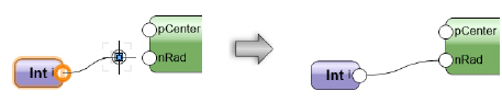
1 Using the Selection tool, click the control point on a node output port; then, move the cursor and click on a node input port.
Ensure that the Disabled Interactive Scaling mode of the Selection tool is disabled (turned off).
2 The two ports are connected by a wire. The outputs from any given node can be connected to multiple inputs on other nodes; likewise, multiple outputs can be connected to a single input node.
To neaten up a complex network, use the Align/Distribute commands to arrange the nodes; the wiring is not affected. (See Aligning and Distributing Objects.)
Naming nodes is an important part of creating and organizing a network, and impacts wrapper nodes significantly; for more information, see Marionette Wrapper Nodes. Name input nodes and the nodes they are attached to in order to easily remember individual stages of more complicated networks. To name a node, select the node and enter a Name in the Object Info palette.
Named input nodes appear as fields on the Object Info palette of wrapper nodes; name them to quickly recognize and adjust values without having to edit the actual wrapper node.
The named inputs display in alphabetical order on the wrapper node.
The unused ports of named nodes display on wrapper nodes for easy connection to other networks. This is another good reason to name nodes.

To edit a network:
1 Select a node or wire to change.
In the network pictured above, select the wire connecting the Oval node to the Column node.
2 To disconnect the wire, select the control point located on the input port.
In the network pictured above, select the control point located on the “profile” input of the Column node.
3 Connect the wire to a different input port, or remove the wire by clicking in a blank area of the drawing.
If a node is deleted, all associated wires are also deleted.
Command |
Path |
|---|---|
Run Marionette Script |
Context menu |
To run the Marionette script, right-click on any node in the network and select the command. Alternatively, select Run from the Object Info palette.
If an error occurs when running the script, an Execution Error dialog box opens, providing information about the type of error and its location in the script.
Objects created by running the script are grouped when the script completes execution. Running a script consecutive times replaces grouped objects created from the previous execution of the script; to retain the objects, rename the group or ungroup the objects.
The Debug mode of the Marionette tool enables the troubleshooting of networks when they are not functioning as desired. In debug mode, a number appears next to each output port, representing the number of values traveling from that output port to any attached input ports. Clicking on a wire opens the Marionette Wire Value dialog box, displaying the values that travel through the wire. The script executes upon closing the dialog box.
To cache the wire values, click Preferences, and select Cache Last Run in Debug Mode. With this mode enabled, you can view the wire values without re-executing the script.

~~~~~~~~~~~~~~~~~~~~~~~~~
 Marionette Wrapper
Nodes
Marionette Wrapper
NodesCommand |
Path |
|---|---|
Wrap Marionette Network |
Context menu |
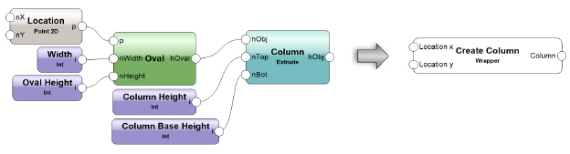
Wrapper nodes consolidate an entire network into a single executable node, with a customized name and description.
To create a wrapper node:
1 Right-click on any node in the network and select the command.
The Wrap Marionette Network dialog box opens.
2 Enter a Name and description for the wrapper node.
To edit a wrapper description:
1 Select a wrapper node.
2 Click Edit Description from the Object Info palette.
Alternatively, right-click on a wrapper node and select Edit Description from the context menu.
The Wrap Marionette Network dialog box opens.
3 Edit the Name and description.
The inputs of the network within a wrapper node can be edited from the Object Info palette if they are named in the network; for more information, see Naming Nodes.
Unused inputs and outputs display on the wrapper node if the nodes to which they belong are named; this is useful for quickly incorporating wrapper nodes into larger Marionette scripts or complex networks.
The display of unused ports on the wrapper node can be controlled. Unwrap or edit the wrapper node, and then use the 2D Locus tool to place a locus on each unused port intended to be hidden.
Command |
Path |
|---|---|
Unwrap Marionette Network |
Context menu |
To unwrap a wrapper node back into the unconsolidated network, select the command.
To edit a network within a wrapper node:
1 Select the wrapper or object node.
2 Click Edit from the Object Info palette.
Alternatively, right-click on the object or wrapper node and select Edit Script from the context menu.
A colored border around the drawing window indicates that you are in an editing mode. The Exit Marionette Script button is visible in the top right corner of the drawing window.
3 Make the desired changes to the network; see Editing a Network for more information.
4 Click Exit Marionette Script to return to the drawing.
~~~~~~~~~~~~~~~~~~~~~~~~~
 Creating Menu
Commands from Wrapper Nodes
Creating Menu
Commands from Wrapper NodesCommand |
Path |
|---|---|
Convert to Menu Command |
Context menu |
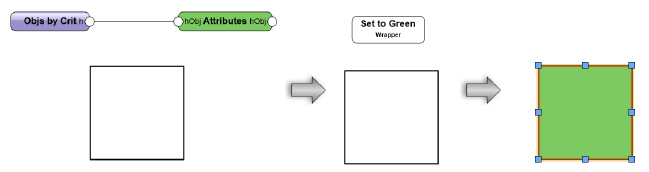
Wrapper nodes can be converted to menu commands, including commands that require object selection. Menu commands created by Marionette are available in any of the Vectorworks Designer workspaces.
To create a menu command from a wrapper node:
1 Select the command.
The Convert Marionette to Menu Command dialog box opens.
2 Enter a name for the menu command.
The Marionette commands are saved in the Marionette Command Library file, located in the User/Libraries/Defaults/Marionette folder. They are loaded dynamically every time Vectorworks launches or a new command is created.
3 To execute the command, select Tools > Marionette Commands, and select the command from the list.
Marionette commands cannot be edited through the Workspace Editor.
To edit an existing Marionette command:
1 Access the wrapper node on which the command is based. If the wrapper node is not in the drawing, the wrapper node resource can be imported from the Marionette Command Library file in the Resource Manager.
Marionette commands cannot be edited directly from the Marionette Command Library file.
2 Edit the network in the wrapper node, as described in Editing Networks in Wrapper or Object Nodes.
3 Convert the edited wrapper node to a menu command, as described in Creating Menu Commands from Wrapper Nodes.
4 Choose whether to replace the existing Marionette command or create a new one.
• To create a new command, enter a new command name in the Convert Marionette to Menu Command dialog box.
• To replace the existing Marionette command, enter the same command name in the Convert Marionette to Menu Command dialog box. When the Resource Name Conflict dialog box opens, select Replace the Symbol Definition in the target document.
~~~~~~~~~~~~~~~~~~~~~~~~~
 Using Object Nodes
Command |
Path |
|---|---|
Context menu |
Object nodes are wrapper nodes that take the form of the product of their executed script. The benefits of an object node include being able to immediately see the effects of modifying a network without having to execute the script.
To convert a wrapper node to an object node:
Select the command.
Select Reset On Move from the Object Info palette to reset the object node each time it is moved.
If Reset On Move is disabled, the object node resets only when its parameters are changed. This can save time when moving complex objects.
Command |
Path |
|---|---|
Rename Marionette Object |
Context menu |
After it is created, an object node is named as a “Marionette Object” at the top of the Shape Pane on the Object Info palette. Rename the object node if needed.
To rename the object node.
1 Select the command.
The Rename Marionette Object dialog box opens.
2 Enter the new name for the object. The name displays as the object type at the top of the Shape pane of the Object Info palette.
The wrapper node from which the object is named displays in the Wrapper parameter.
Command |
Path |
|---|---|
Edit Control Geometry |
Context menu |
When converting a wrapper node to an object node, you can select a single additional object to convert with the wrapper node to be used as a control geometry. The control geometry enables the creation of custom path objects with Marionette. For example, if the object node requires a Duplicate Along Path object, you can include a polyline as the path object.
To edit the object node’s control geometry, select the command.
An object node can be turned back into a wrapper node by right-clicking on the object and selecting Convert to Wrapper Node from the context menu.
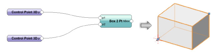
After creation, a Marionette object node can always be resized from the Object Info palette parameters, but it is much easier to resize the object with resize handles, similar to Vectorworks objects. To be able to resize objects, include special nodes in the script.
To add the ability to resize an object node in Top/Plan and 3D views:
1 When creating the original script or wrapper node (before conversion to an object node), add one or more Control Point 2D nodes and/or Control Point 3D nodes (located in the Input category) to the p input port of the nodes that should receive a handle. These Control Point nodes include information about the X and Y, or X, Y, and Z, coordinates relative to the object’s origin location.
2 Convert the script to a wrapper node, and then to an object node.
3 Use the handles to resize the object.
[This graphic shows a bad example currently because the object disappears when resized. Marissa will send another. AD 7/18]
~~~~~~~~~~~~~~~~~~~~~~~~~
 Saving
and Exporting Marionette Networks
Saving
and Exporting Marionette NetworksCommand |
Path |
|---|---|
Save Marionette Script as Python Script |
Context menu |
Saving a Marionette network as a Python script is recommended for advanced users as a method for debugging scripts that are not working correctly.
To save any Marionette network or node as a Python script:
1 Select the command.
The Save as Python Script dialog box opens.
2 Specify the file name and destination, and then click Save.
Any Marionette network, node, or object can be converted into a red symbol for ease of sharing and reuse. This allows you to reuse or share potentially complex scripts with less experienced users, opening up the possibility of creating and sharing custom plug-in objects.
To create a customized library of Marionette nodes:
1 Create a symbol for each node, with the node in the symbol, as described in Creating Symbol Definitions. Name the symbol with the name of the node it contains. Select Convert to Plug-in Object to create a red symbol.
2 Save the file of symbols in your user folder, in the Libraries/Defaults/Marionette folder.
Place the network symbol in a wrapper node to use the network contained within the symbol. Multiple object node red symbols with complex networks can affect computer performance.
An object node can also be converted to a black symbol for reuse. This allows you to share a Marionette-created object with other users without easily allowing access to the original script.
See Concept: Vectorworks Symbols for more information.
~~~~~~~~~~~~~~~~~~~~~~~~~
 Marionette
Tutorial: Creating a Simple Extrude
Marionette
Tutorial: Creating a Simple ExtrudeThis simple tutorial explains how to get started with placing Marionette nodes, entering input values, and connecting nodes. The Marionette script is executed to create an extruded column.
To decide which nodes need to be placed to create an extruded column, think about how you would create a column in a Vectorworks drawing. You might draw a circle with a certain radius, and then extrude it. Therefore, at a minimum, you need a node to create a circle, a node to set the radius of the circle, and a node to perform an extrude operation.

To place the required Marionette nodes:
1 In Top/Plan view, click the Marionette tool from the Basic palette, and click Insert mode.
2 Click Current Node on the Tool bar. From the Resource Selector, locate the Objects category of node objects, and double-click on the Circle node resource to select that node.
3 Click in the drawing to place the node.
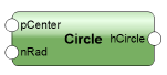
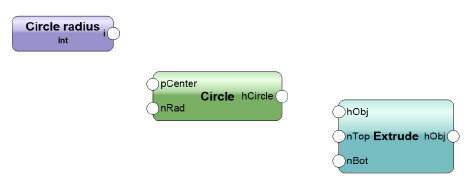
4 Looking at the placed node, you can see that it has two possible inputs: a radius value and a center point. We will add a radius value. With the Marionette tool still selected, locate the Input category from the Current Node Resource Selector and double-click to select the Integer node resource.
5 Click in the drawing to place the Integer node.
6 We will create a circle with a radius of 4. With the node selected, enter a value of 4 for Integer in the Object Info palette. For Name, type Circle radius. This helps you identify the purpose of this integer node. It is a good idea to name such nodes for easy identification, especially later on with complex scripts.
7 With the Marionette tool still selected, locate the Objects category from the Resource Selector and double-click to select the Extrude node resource.
8 Click in the drawing to place the Extrude node.
To connect the nodes and create the extrude with the script:
1 With the Selection tool, connect the output from the Integer node to the radius input of the Circle node, and then connect the output from the Circle node to the profile input of the Extrude node.
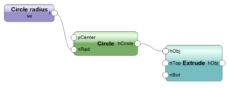
2 To run the Marionette script, right-click on any node in the network and select Run Marionette Script from the context menu. Alternatively, select Run from the Object Info palette.
3 The extruded object is created. It is selected and saved as a group, but it can be ungrouped to access the extrude.
You have created your first Marionette script!
 Marionette
Tutorial: Creating a Simple Cabinet
Marionette
Tutorial: Creating a Simple CabinetThis more advanced tutorial demonstrates how to create a simple open-faced cabinet composed of three rectangular prisms, one each for the top, body, and cavity.
Create a rectangular prism (an extruded rectangle) to serve as the body of the cabinet. For now, the body is a solid object; later steps in the process will create a top for the cabinet and a cavity in the body.
To create a network that defines the rectangular prism:
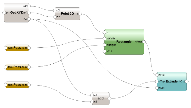
1 Insert the following nodes to create a network as illustrated.
Use the Search functionality in the Resource Selector to help you find the nodes you need.
• Rectangle node: this serves as the shape on which the cabinet is based; its dimensions are defined by other nodes. The rectangle is wired to the Extrude node to define the profile to be extruded.
• Extrude node: with inputs from all the other nodes, this serves as the 3D base shape for the cabinet.
• Get XYZ node: this node reads the values provided by a 3D Point or 3D Vector node, and separates the values into the X, Y, and Z components.
• Point 2D node: the X and Y values are used to create a 2D point that defines the location of one corner of the rectangle.
• Three Pass nodes: these are wired to the width and height ports of the Rectangle node and to the Add node. Pass nodes simply send what goes into the node back out of the node. In this example, Pass nodes are only for organizational purposes.
• Add node: this adds the Pass node output to the Z value from the Get XYZ node to determine the top of the extrude.
2 Connect the wires as illustrated.
~~~~~~~~~~~~~~~~~~~~~~~~~
 Step
2: Create and Copy a Wrapper Node
Step
2: Create and Copy a Wrapper NodeWrap the network of nodes to make the script more readable on the monitor, and to make it easy to duplicate the code.
To create a wrapper node:
1 Right-click on any node in the network, and select Wrap Marionette Network from the context menu.

The network becomes a wrapper node.
To allow inputs and outputs to the wrapper, the wrapped nodes must be named. In this example, you need to provide access to the origin of the rectangular prism, its dimensions (width, depth, and height), and the resulting extruded object.
2 Double-click on the wrapper to enter object editing mode and access the Marionette script inside the wrapper.
3 Select each node listed, and enter its Name in the Object Info palette.
Node |
Name |
|---|---|
Get XYZ |
Origin |
Pass (attached to Width input on Rectangle node) |
Width |
Pass (attached to Height input on Rectangle node) |
Depth |
Pass (attached to Add node) |
Height |
Extrude |
obj |
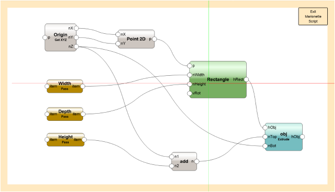
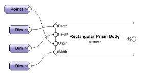
4 Click Exit Marionette Script to return to your drawing. The wrapped network displays with the named nodes that can be accessed.
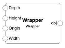
5 Select the wrapper node, and enter the Name Rectangular Prism Body in the Object Info palette.
6 Make two copies of the Rectangular Prism Body wrapper. These will serve as the basis for the cabinet top and cavity in future steps; the parameters will be redefined for each piece of the cabinet.

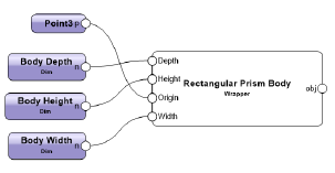
7 On the original wrapper node (the body), attach a 3D Point node to the Origin port and a Dimension node to each of the other ports. Connect the wires.
8 Select each Dim node, and assign the following names and dimension values in the Object Info palette.
Body Prism Port |
Dim Node Name |
Value |
|---|---|---|
Width |
Body Width |
3 feet |
Depth |
Body Depth |
2 feet |
Height |
Body Height |
3.5 feet |
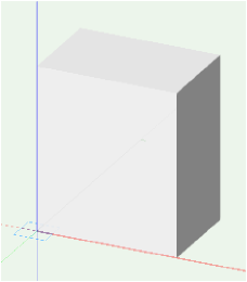
9 Select a node and click Run from the Object Info palette.
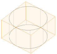
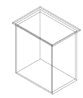
The rectangular prism displays with its bottom front left corner at the assigned origin (0,0,0). This is the cabinet body. The prisms that compose the cabinet top and cavity are defined relative to the origin and dimensions of this base object.
You can download the tutorial at this stage here (internet access required).
~~~~~~~~~~~~~~~~~~~~~~~~~
 Step
3: Add a Top
Step
3: Add a TopThe location and size of the cabinet’s top surface will be calculated based on the body’s rectangular prism.
To add the cabinet top:
1 Select one of the Rectangular Prism Body wrapper node copies, and enter the Name Rectangular Prism Top in the Object Info palette.
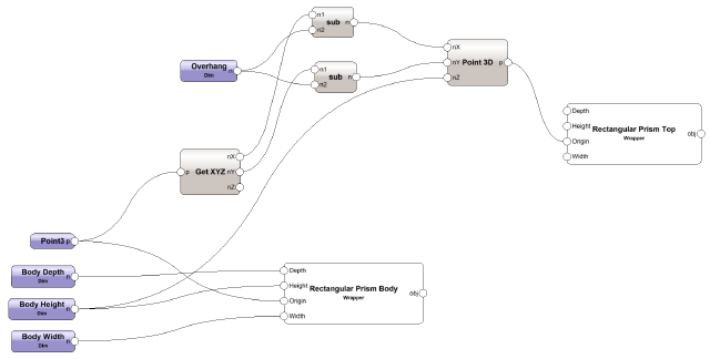
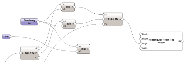
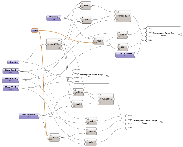
2 Insert the following nodes to create a network as illustrated.
• Get XYZ node: the X and Y locations of the top of the cabinet are based on those of the body, and are altered by the two Subtract nodes to provide a defined overhang offset. The bottom surface of the cabinet top is located at the same Z value as the top of the body, so the Body Height node can bypass the Get XYZ node and be wired directly into the Z port of the new Point 3D node.
• Dim node: this will specify an overhang offset. Name this node Overhang. Because the offset will be the same on all sides, the same overhang node connects to both Sub nodes; the value of this node is defined later.
• Two Sub nodes: these nodes subtract the dimension provided by the Overhang node from the X and Y locations to help define the top’s offset.
• Point 3D node: the X, Y, and Z locations for the top are calculated based on those of the cabinet body; if the dimensions of the body change, the top automatically updates as well.
3 Connect the wires to the Rectangular Prism Top wrapper as illustrated.
4 To make the top of the cabinet wider and deeper than the body, multiply the overhang dimension by two.
• Add an Int node and assign it a Value of 2.
• Add a Multiply node to serve as the multiplier.
5 Connect the wires.
6 Add the multiplier to the Width and Depth of the top of the cabinet by inserting two Add nodes. To control the height of the top, add a Dim node named Top Thickness to the top Height. Connect the wires.
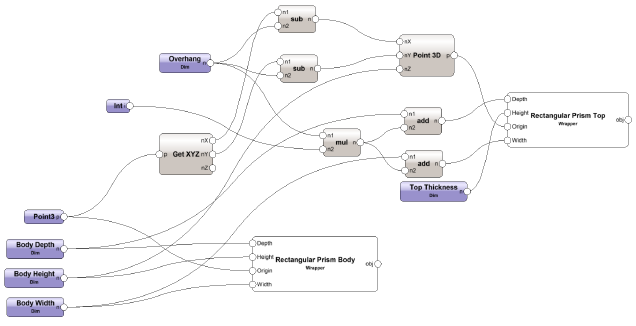
7 Enter a value of 1.5” for the Overhang and 1” for the Top Thickness.
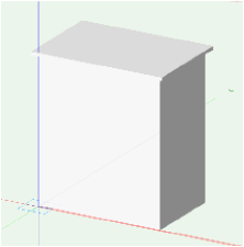
8 Select a node and click Run from the Object Info palette.
A rectangular prism displays at the assigned origin with the prescribed dimensions to add a top to the cabinet body.
You can download the tutorial at this stage here (internet access required).
~~~~~~~~~~~~~~~~~~~~~~~~~
 Step
4: Cut Out the Cavity
Step
4: Cut Out the CavityThe third rectangular prism copy defines the prism to be removed from the solid body of the cabinet. It is also calculated based on the body’s rectangular prism.
To create the cavity and subtract it from the body:
1 Select the remaining Rectangular Prism Body copy and enter the Name Rectangular Prism Cavity in the Object Info palette.
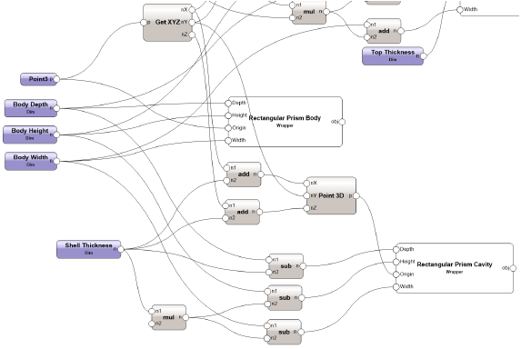
2 Only one more dimension is needed to define the new prism. Add a Dim node and name it Shell Thickness.
3 The X and Z coordinate values will consider the Shell Thickness with two Add nodes. Because this cabinet has an open face, the Y value for the cavity will come directly from the body. Connect the wires.
• Add the Shell Thickness to the X value and the Z value on a Point 3D.
• Connect the Y from the Get XYZ node directly to the Y port on the Point 3D node.
4 Three Sub nodes provide the cavity dimensions. Connect the wires.
• The Width is equal to the body width minus two times the shell thickness.
• The Depth is equal to the body depth minus the shell thickness.
• The Height is equal to the body height minus two times the shell thickness.
• Add a Multiply node to serve as the multiplier.
5 Set the Shell Thickness node value to 1”.
6 Connect the Int node to the Multiply node to set a factor of 2.
7 To cut the cavity from the body, use a Solid Boolean node. In the Object Info palette, select Subtract from the operation list. Connect the wires.

8 Select a node and click Run from the Object Info palette. Render the cabinet to see the cavity.
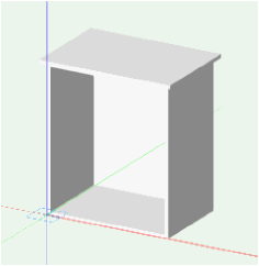
You can download the tutorial at this stage here (internet access required).
~~~~~~~~~~~~~~~~~~~~~~~~~
 Step
5: Create a Marionette Object
Step
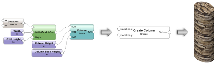
5: Create a Marionette ObjectThe final step is to turn the entire script into a Marionette object.
1 Right-click on any node in the network, and select Wrap Marionette Network from the context menu.
2 Right-click on the Wrapper node and select Convert to Object Node from the context menu.
The Marionette object is created. The Object Info palette displays the available parameters; change the parameters to update the object.
You can download the final tutorial file here (internet access required).
