
As restrições paramétricas garantem que um desenho mantenha sua precisão original mantendo as relações entre um objeto e o espaço mundial, entre dois objetos ou dentro do próprio objeto. Existem dois tipos de restrições paramétricas: dimensional e geométrica. As restrições dimensionais mantêm um relacionamento mensurável ao limitar a geometria do objeto a um valor específico. As restrições geométricas mantêm um relacionamento físico limitando a orientação permitida dos objetos.
Restrições paramétricas podem ser colocadas em todos os objetos 2D. Eles não podem ser colocados em objetos 3D, exceto paredes, símbolos e objetos de plug-in que tenham componentes 2D. Várias restrições podem ser aplicadas a um objeto. As restrições paramétricas podem ser colocadas em camadas, desde que as duas camadas tenham a mesma escala e as Opções de Camada estejam definidas como Show/Snap/Modify Others.
As restrições devem sempre ser colocadas no plano definido pelo objeto ou objetos que estão sendo constrangidos; quando vários objetos são restritos, eles devem ser co-planares para criar a restrição. A restrição em um objeto ou objetos altera os planos com o objeto, se o objeto alterar seu plano.
As restrições associadas a um único objeto permanecem anexadas, mesmo se o objeto for copiado ou recortado e colado. Se você excluir um objeto de um grupo de objetos restritos, todas as restrições anexadas ao objeto excluído serão removidas.
Quando uma restrição paramétrica é colocada, os indicadores de restrição verde são desenhados para o (s) objeto (s) envolvido (s). Para ocultar indicadores, desmarque Mostrar restrições paramétricas na guia Exibição das preferências do Vectorworks. Como alternativa, selecione Exibir> Mostrar> Mostrar ou ocultar restrições; o comando alterna entre exibir ou ocultar restrições.
~~~~~~~~~~~~~~~~~~~~~~~~~
As restrições dimensionais mantêm um relacionamento mensurável ao vincular a geometria de um objeto a um valor específico. Eles se assemelham as dimensões padrão quando colocados.
~~~~~~~~~~~~~~~~~~~~~~~~~
Tool |
Tool set |
|---|---|
Constrain Angle
|
Dims/Notes |
Multiple dimensional constraint tools share the same position on the tool set. Click and hold the mouse on the visible tool to open the Pop-out Tools list and select the desired tool.
Constrain the angular relationship between separate objects or line segments of a single object. If one object or segment is rotated, the object or segment it is constrained to adjusts to maintain the angle.
To constrain the angle between objects or line segments of a single object:
1 Click the tool.
2 Click one of the two objects or line segments to be constrained.
3 Click the second object or line segment to be constrained.
A green angle constraint is drawn between the two objects or line segments.

Tool |
Tool set |
|---|---|
Constrain Radius
|
Dims/Notes |
Multiple dimensional constraint tools share the same position on the tool set. Click and hold the mouse on the visible tool to open the Pop-out Tools list and select the desired tool.
Constrain the radius of a single arc or circle. This prevents an arc or circle from being accidentally resized.
To constrain the radius of an arc or circle:
1 Click the tool.
2 Click the arc or circle to be constrained.
A green radius constraint is drawn on the object.

The Constrain Radius tool does not work on quarter arcs.
Tool |
Tool set |
|---|---|
Constrain Horiz Distance
|
Dims/Notes |
Multiple dimensional constraint tools share the same position on the tool set. Click and hold the mouse on the visible tool to open the Pop-out Tools list and select the desired tool.
Constrain the horizontal distance of an edge of an object, a line segment, or between two points. If an object resize is attempted, the constraint prevents the operation, preserving the original horizontal distance. When the constraint is on two different objects, if one object is modified, the other constrained object moves to remain at the same constrained horizontal distance.
To constrain the horizontal distance of an edge of an object or a line segment:
1 Click the tool.
2 Click the object to be constrained.
A green horizontal distance constraint is drawn on the object.

To constrain the horizontal distance between two points:
1 Click the tool.
2 Click the first point to be constrained.
3 Click the second point to be constrained.
A green horizontal distance constraint is drawn between the two points.

Tool |
Tool set |
|---|---|
Constrain Vertical Distance
|
Dims/Notes |
Multiple dimensional constraint tools share the same position on the tool set. Click and hold the mouse on the visible tool to open the Pop-out Tools list and select the desired tool.
Constrain the vertical distance of an edge of an object, line segment, or between two points. If an object resize is attempted, the constraint prevents the operation, preserving the original vertical distance. When the constraint is on two different objects, if one object is modified, the other constrained object moves to remain at the same constrained vertical distance.
To constrain the vertical distance of an edge of an object or line segment:
1 Click the tool.
2 Click the object to be constrained.
A green vertical distance constraint is drawn on the object.

To constrain the vertical distance between two points:
1 Click the tool.
2 Click the first point to be constrained.
3 Click the second point to be constrained.
A green vertical distance constraint is drawn between the two points.

Tool |
Tool set |
|---|---|
Constrain Distance
|
Dims/Notes |
Multiple dimensional constraint tools share the same position on the tool set. Click and hold the mouse on the visible tool to open the Pop-out Tools list and select the desired tool.
Constrain the distance of an edge of an object, line segment, or between two points regardless of the angle. The constraint prevents an accidental resize operation, preserving the original distance. When the constraint is on two different objects, if one object is modified, the other constrained object moves to remain at the same constrained distance.
To constrain the distance of an edge of an object or line segment:
1 Click the tool.
2 Click the object to be constrained.
A green horizontal distance constraint is drawn on the object.

To constrain the distance between two points:
1 Click the tool.
2 Click the first point to be constrained.
3 Click the second point to be constrained.
A green distance constraint is drawn between the two points.

Geometric constraints limit the allowed orientation of objects.
~~~~~~~~~~~~~~~~~~~~~~~~~
Tool |
Tool set |
|---|---|
Constrain Horiz-Vertical
|
Dims/Notes |
Multiple dimensional constraint tools share the same position on the tool set. Click and hold the mouse on the visible tool to open the Pop-out Tools list and select the desired tool.
Constrain a linear object to remain horizontal or vertical. Once constrained, the object cannot be rotated to any other position. The object can be resized in length, but it always remains horizontal or vertical.
To constrain an object to remain horizontal-vertical:
1 Click the tool.
2 Click the linear object to be constrained.
A green horizontal-vertical constraint is drawn on the object.

If the object is diagonal when the constraint is placed, it rotates to become vertical or horizontal (whichever is closest).
Tool |
Tool set |
|---|---|
Constrain Parallel
|
Dims/Notes |
Multiple dimensional constraint tools share the same position on the tool set. Click and hold the mouse on the visible tool to open the Pop-out Tools list and select the desired tool.
Constrain linear objects to be parallel to one another. If one object is rotated, the other constrained object rotates to remain parallel to the first object. The lines do not need to be parallel when you place the constraint; the first line rotates to match the angle of the second line.
To constrain linear objects or line segments to be parallel:
1 Click the tool.
2 Click the line to constrain.
3 Click the line to be constrained.
Green parallel constraint indicators are drawn around the two lines.

Tool |
Tool set |
|---|---|
Constrain Perpendicular
|
Dims/Notes |
Multiple dimensional constraint tools share the same position on the tool set. Click and hold the mouse on the visible tool to open the Pop-out Tools list and select the desired tool.
Constrain linear objects to be perpendicular to one another. If one line is rotated, the other constrained line adjusts to remain perpendicular to the first line. The lines do not need to be perpendicular when you place the constraint; the first line rotates to become perpendicular to the second line.
To constrain lines to be perpendicular:
1 Click the tool.
2 Click the line to constrain.
3 Click the line to be constrained.
A green perpendicular constraint is drawn, connecting the two lines.

Tool |
Tool set |
|---|---|
Constrain Collinear
|
Dims/Notes |
Multiple dimensional constraint tools share the same position on the tool set. Click and hold the mouse on the visible tool to open the Pop-out Tools list and select the desired tool.
Constrain the collinearity between two linear objects. If one line is moved, the other constrained line adjusts to remain aligned. The lines do not need to be aligned when you place the constraint; the first line moves to become collinear to the second line.
To constrain the collinearity between two lines:
1 Click the tool.
2 Click the line to constrain.
3 Click the line to be constrained.
Green collinear constraint indicators are drawn on the two lines.

Tool |
Tool set |
|---|---|
Constrain Coincident
|
Dims/Notes |
Multiple dimensional constraint tools share the same position on the tool set. Click and hold the mouse on the visible tool to open the Pop-out Tools list and select the desired tool.
Constrain two selected points to remain attached. If one object is moved, the other constrained object adjusts to maintain the connection. The first point stretches to connect to the second point, if necessary.
To constrain the connection between two points:
1 Click the tool.
2 Click the point to constrain.
3 Click the point to be constrained.
A green coincident constraint is drawn where the two points touch.

Tool |
Tool set |
|---|---|
Constrain Concentric
|
Dims/Notes |
Multiple dimensional constraint tools share the same position on the tool set. Click and hold the mouse on the visible tool to open the Pop-out Tools list and select the desired tool.
Constrain circles and arcs concentrically. If a circle or arc is moved, the other constrained circle or arc moves so that their centers remain aligned. The circles or arcs do not need to be concentric when you place the constraint; the first object moves so that its center aligns to the second object’s center.
To constrain two circles or arcs concentrically:
1 Click the tool.
2 Click the object to constrain.
3 Click the object to be constrained.
A green concentric constraint is drawn at the center of the two objects.

Tool |
Tool set |
|---|---|
Constrain Tangent
|
Dims/Notes |
Multiple dimensional constraint tools share the same position on the tool set. Click and hold the mouse on the visible tool to open the Pop-out Tools list and select the desired tool.
Constrain a circle, arc, or line to be tangent to another circle or arc. If one object is moved, the other constrained object adjusts to maintain the tangency. The objects do not need to be tangent to one another when you place the constraint; the first object moves to become tangent to the second.
To constrain a circle, arc or line to be tangent to a circle or arc:
1 Click the tool.
2 Click the circle or arc to constrain.
3 Click the circle, arc, or line to be constrained.
A green tangent constraint is drawn at the tangent point of the two objects.

When a constrained object is deleted, the parametric constraint attached to it is also removed. To remove the constraint without removing the attached object, use the Edit Constraints command.
A situation may arise where the value of a dimensional constraint needs to be changed. A wall with a horizontal distance constraint value of 2’ 6” may at a later point in the project need to be changed to 5’ 6”. This type of edit is also accomplished using the Edit Constraints command.
Individual constraints can be selected from a list of all constraints currently applied to a selected object. The selected constraint changes color to indicate which one is about to be edited. Geometric constraints, where appropriate, along with changing the constraint color, also show the connection between the two constrained objects for clarity.
Constraint errors related to editing operations that conflict with current constraints are solved by either removing the constraint, or canceling the editing operation.
~~~~~~~~~~~~~~~~~~~~~~~~~
Command |
Path |
|---|---|
Edit Constraints |
Modify |
You can select which constraints to delete or delete all constraints at once. Constraints can be removed or edited for multiple selected objects.
To select which parametric constraint to delete:
1 Select the object with the constraint.
2 Select the command.
The Edit Constraints dialog box opens.
3 Select the constraint to be removed from the Constraints list.
The selected constraint changes color.
4 Click Delete to remove the constraint.
To delete all parametric constraints:
1 Select the object(s) with the constraints.
2 From the context menu, select Remove Constraints. Alternatively, select Delete All from the Edit Constraints dialog box.
Using the Remove Constraints context menu command will also disassociate any associated dimensions.
~~~~~~~~~~~~~~~~~~~~~~~~~
Command |
Path |
|---|---|
Edit Constraints |
Modify |
To change a dimensional constraint value:
1 Select the object with the constraint.
2 Select the command.
The Edit Constraints dialog box opens.
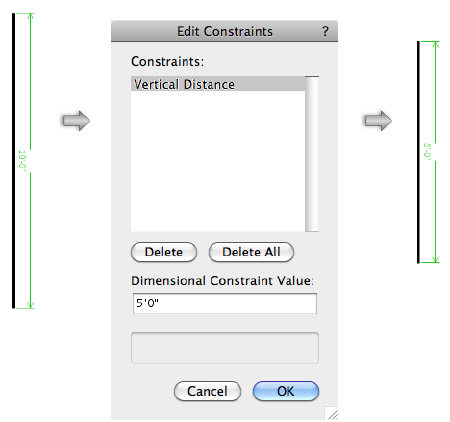
3 In the Dimensional Constraint Value field, enter the new dimension.
The dimensional value is updated and the object or objects are adjusted.
~~~~~~~~~~~~~~~~~~~~~~~~~
Occasionally, an editing operation cannot be performed due to conflicting or unsolvable constraints placed on the objects involved. When this occurs, an alert dialog box opens to preview the unsolvable constraints and remove them if needed.
To solve conflicting constraint errors:
1 When an unsolvable constraint occurs, an alert dialog box opens. Decide how to resolve the conflicting situation.
► Click to show/hide the Parâmetros.
2 Select Preview constraints that will be selected, and then click Yes to preview the unsolvable constraints.
The Unsolvable Constraints dialog box opens.
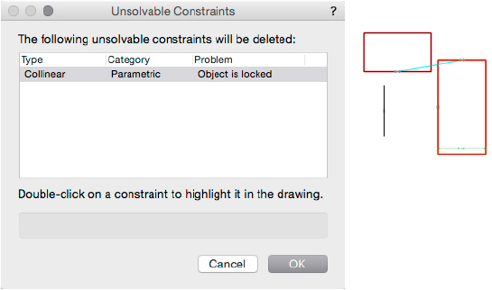
3 Double-click an unsolvable constraint to preview it in the drawing. The unsolvable constraint displays with a different color.
4 Click OK to remove the constraints and perform the editing operation. Click Cancel to retain the constraints and cancel the editing operation.
~~~~~~~~~~~~~~~~~~~~~~~~~


