Janelas
Nos produtos
Vectorworks Design Series, o objeto de janela é inserido com a ferramenta
Janela. No Vectorworks Fundamentals, o objeto de janela é inserido a partir
de uma biblioteca de objetos acessível pelo Administrador de Recursos.
Todos os produtos Vectorworks incluem um objeto de janela com parâmetros
semelhantes aos descritos aqui. O Vectorworks Architect e Landmark possuem
recursos adicionais.
O Vectorworks
Architect e Landmark incluem símbolos de janelas em tamanhos padrão e
em diversas configurações, prontos para serem instalados em paredes. Estes
produtos também permitem a inserção de janelas em paredes cortina como
"janelas de parede cortina" especiais". Além disso o Vectorworks
Architect traz uma completa biblioteca de símbolos de janela, agrupados
pela configuração e pelo tamanho. No Vectorworks Architect, a informação
relativa à energia especifica para portas são consideradas quando a realização
de uma análise energética.
O comando
Atualizar Objetos Plug-in pode precisar ser executado em arquivoq eu contenham
janelas criadas em uma versão anterior do Vectorworks Architect ou Landmark.
Este comando converte as janelas para o formato mais recente. Veja “Migrando de Versões Anteriores” na página 25.
Uma janela
pode ser personalizada ajustando-se os diversos parâmetros e então salvando-a
como um símbolo de modo que seus parâmetros sejam reutilizados ao inseri-la.
Isto elimina a necessidade de alterar novamente os parâmetros, aumentando
a eficiência da memória e permitindo a edição global de símbolos. Veja
“Criando Novos Símbolo” na página 235.
Se uma
janela personalizada for única em um projeto (ou seja, se existe apenas
uma instância), não é necessário criar um símbolo a partir dela. No entanto,
criar um símbolo a partir de uma janela instalada torna mais fácil reutilizá-la
em outros desenhos caso seja necessário fazê-lo no futuro.
Depois
que o símbolo for criado ele poderá ser selecionado em Ajustes da Janela
(escolhendo Usar Geometria do Símbolo como descrito em “Window
Settings: General Pane” na página 590), onde ele poderá
utilizar recursos como IDs e dados embutidos, envolvimento de cavidades,
chanfrados e deslocamentos de parede. Para ativar a rotulagem automática
a partir da aba Tag com ID da janela de configurações, escolha Incluir
no Cronograma e especifique os parâmetros da ID. Se necessário, escolha
a classe para a qual a ID foi definida como visível. Se preferir, defina
a rotulagem automática através da ferramenta Rótulo do ID. Veja “Using the ID Label Tool” na página 1257.
~~~~~~~~~~~~~~~~~~~~~~~~~
Inserindo janelas no Vectorworks Fundamentals
Inserting Windows in Vectorworks Design
Series
Inserindo
janelas no Vectorworks Fundamentals
Para
inserir uma janela no Vectorworks Fundamentals:
1
Insera um símbolo janela no Administrador de Recursos (veja
“Inserting Symbols” na página 278).
A direção de uma janela inserida em uma parede pode ser alterada mais
tarde clicando em Inverter a partir da paleta Informações do Objeto ou
no menu de contexto.
Uma
biblioteca com um símbolo janela editável está incluso com o produto Vectorworks
Fundamentals. Se o conteúdo não foi baixado durante a instalação, você
pode baixá-lo a qualquer momento selecionando Ajuda> Download de conteúdo
(veja “Resource Libraries” na página 251).
A
ferramenta da janela está disponível para o software Vectorworks Fundamentals,
mas não está presente na área de trabalho Fundamentals. Ele pode ser adicionado
à área de trabalho Fundamentals (veja “Creating
or Editing Workspaces” na página 2065) e, posteriormente, utilizado
para inserir objetos janela.
2.
Clique no botão Configurações na paleta Informações de Objeto para abrir
a janela Ajustes da Janela. Acesse cada painel e especifique os parâmetros
desejados. Clique em OK para definir os parâmetros e fechar a janela.
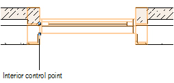
Alguns
recursos da janela são descritos como "interior" ou "exterior".
Estes recursos incluem guranições, venezianas e envolvimento de partes
da parede. Estes elementos são determinados com base nas faces interior
e exterior da parede, e não na direção exterior da janela. O lado esquerdo
da parede (como visto ao longo da direção da parede) será sempre o exterior,
e o lado direito será o interior (veja “Direção
da Parede” na página 502). Inverter a janela não inverte estes
elementos.
Ajustes da Janela: Prévia
Clique para
exibir ou esconder os parâmetros.
Ajustes da Janela: Painel Geral
Clique para
exibir ou esconder os parâmetros.
Ajustes da Janela: Painel de Visualização 2
Clique para
exibir ou esconder os parâmetros.
Ajustes da Janela: Painel de Visualização 3D
As opções
de visualização 3D não estarão ativas na configuração de Caixilho de Abertura.
Clique para
exibir ou esconder os parâmetros.
Window Settings: ID Tag
Pane
Click to
show/hide the parameters.
Window Settings: Jamb and Sash Pane
Click to show/hide the parameters.
Window Settings: Sill
Pane
Click to show/hide the parameters.
Window Settings: Transom
Pane
Click to show/hide the parameters.
Window Settings: Trim
Pane
Click to show/hide the parameters.
Window Settings: Muntins Pane
Click to show/hide the parameters.
Window Settings: Interior Wall Detail Pane
Click to show/hide the parameters.
Window Settings: Exterior Wall Detail Pane
Click to show/hide the parameters.
Window Settings: Classes Pane
The visibility of the overall 3D window is controlled
by the Class setting from the Object
Info palette; part settings are controlled from the Window Settings dialog
box.
Click to show/hide the parameters.
Window Settings: Data
Pane
Certain data fields represent calculated values and
cannot be edited; as a result, the Field Name and
Field Value appear dimmed for those
data fields.
Click to show/hide the parameters.
~~~~~~~~~~~~~~~~~~~~~~~~~
Janelas
Inserting
Windows in Vectorworks Design Series
Window
Properties
Creating
Window Schedules
Creating
a Custom Window Sash Opening
Window
Terminology Specific to the United Kingdom
Editing
Symbols in Walls
 Inserting Windows in Vectorworks Design
Series
Inserting Windows in Vectorworks Design
Series

To insert a window in Vectorworks Design Series:
1 Select the Window tool from the Building Shell tool set.
Alternatively, if placing a curtain wall window
into a curtain wall (Vectorworks Architect or Landmark required), select
a panel with the Edit Curtain Wall tool,
and then right-click (Windows) or Ctrl-click (Mac) on the panel and select
Insert Window from the context menu. The
window is automatically inserted as a curtain wall window.
2 If this is the first time a window
is inserted into the drawing, or if you wish to change the default preferences
that apply to subsequently placed windows, click Preferences from
the Tool bar.
The Window Settings dialog box opens. The settings
are grouped into several panes of related parameters, which are listed
on the left side of the dialog box. Select each pane and specify the window
parameters. Click OK to set the window
parameters and close the dialog box. These parameters can be edited for
placed windows from the Object Info palette, as described in “Window Properties” na página 605.
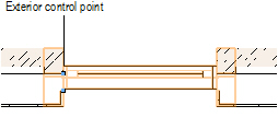
3 Click in the drawing area or in a
wall (standard wall or curtain wall) to set the insertion point of the
window, and click again to set the rotation. When inserting a window into
a wall, place the second click on the exterior side of the wall to establish
the exterior direction of the window. The direction of a window inserted
in a wall can be changed later by clicking Flip
from the Object Info palette.
Several features of the window are described as “interior”
or “exterior.” These include trim, shutters, and wall-wrap parts. These
elements are determined based on the internal and external faces of the
wall, not on the window’s exterior direction. The left side of the wall
(as viewed along the wall direction) is always “exterior,” and the right
side is “interior” (see “Wall Direction”
on page 547). Flipping the window does not flip these elements.
If you are inserting a corner window, place the window
in a wall that is attached to another wall. Once parameters are set, the
window moves to the nearest corner automatically. This represents one
half of the corner window assembly.
Window Settings: Preview
Click to show/hide the parameters.
Window Settings: General
Pane
Click to show/hide the parameters.
Window Settings: 2D
Visualization Pane
Click to show/hide the parameters.
Window Settings: 3D
Visualization Pane
3D Visualization options are not enabled for the Opening
Sash configuration.
Click to show/hide the parameters.
Window Settings: ID
Tag Pane
Click to show/hide the parameters.
Window Settings: Corner
Window Pane
Vectorworks Architect or Landmark product required.
Corner Window options are not enabled for non-rectangular window shapes
or for curtain wall windows.
Click to show/hide the parameters.
Window Settings: Jamb and
Sash Pane
Jamb and Sash options are not enabled for the Opening
Sash configuration.
Click to show/hide the parameters.
Window Settings: Sill
Pane
Sill options are not enabled for the Opening Sash configuration
or for non-rectangular window shapes, or for curtain wall windows.
Click to show/hide the parameters.
Window Settings: Transom
Pane
Transom options are not enabled for the Opening Sash configuration or for non-rectangular
window shapes, or for curtain wall windows.
Click to show/hide the parameters.
Window Settings: Trim
Pane
Trim options are not enabled for the Opening Sash
configuration or for curtain wall windows.
Click to show/hide the parameters.
Window Settings: Lintel
Pane
Vectorworks Architect or Landmark product required.
Lintel options are not enabled for the Opening Sash configuration
or for non-rectangular window shapes, or for curtain wall windows.
Click to show/hide the parameters.
Window Settings: Muntins Pane
Muntin options are not enabled for the Opening Sash configuration or for non-rectangular window
shapes.
Click to show/hide the parameters.
Window Settings: Interior
Shutters Pane
Vectorworks Architect or Landmark product required.
Interior Shutter options are not enabled for the Opening Sash configuration
or for non-rectangular window shapes, or for curtain wall windows.
Click to show/hide the parameters.
Window Settings: Exterior
Shutters Pane
Vectorworks Architect or Landmark product required.
Exterior Shutter options are not enabled for the Opening Sash configuration
or for non-rectangular window shapes, or for curtain wall windows.
Click to show/hide the parameters.
Window Settings: Centerline
Marker Pane
Vectorworks Architect or Landmark product required.
Centerline Marker options are not enabled for curtain wall windows.
Click to show/hide the parameters.
Parameter |
Description |
Centerline Marker |
Select to display a centerline marker
in Top/Plan view. |
Size |
Set the size of the centerline |
Class |
Select a class to control visibility.
The classes present in the drawing are listed; alternatively,
create a new class. Select the default window class to place the
part in the same class as the window object. |
Line Attributes |
Select the line attributes and weight,
or select Set Thickness to open
the Set Thickness dialog box for creating a custom line thickness.
If Use Class Attributes is selected,
the line attributes are set by the part’s class |
Include Marker |
Select whether to include a marker and
choose the desired style from the marker list, or select Custom to create a custom marker.
Select Edit Marker List to open
the Edit Marker List dialog box; see “Editando
a Lista de Marcadores” na página 1100. If Use
Class Attributes is selected, the marker attributes
are set by the part’s class. |
Use Class Attributes |
Select to set the centerline marker’s
attributes (including marker style) by class rather than the parameters
in the Window Settings dialog box |
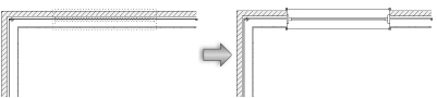
Window Settings: Interior Wall
Detail Pane
Interior Wall Detail options are not enabled for non-rectangular
window shapes or for curtain wall windows.
Click to show/hide the parameters.
Window Settings: Exterior Wall
Detail Pane
Exterior Wall Detail options are not enabled for non-rectangular
window shapes or for curtain wall windows.
Click to show/hide the parameters.
Window Settings: Classes Pane
The visibility of the overall 3D window is controlled
by the Class setting from the Object
Info palette; part settings are controlled from the Window Settings dialog
box.
Click to show/hide the parameters.
 Window Settings:
Energos Pane
Window Settings:
Energos Pane
Windows play a critical role in energy analysis calculations.
Energy is lost through the window glass, but energy is also gained by
solar radiation through the window glass. Accurately determining the R-Value/U-Value
and the shading factor is essential for the overall energy analysis.
Click to show/hide the parameters.
~~~~~~~~~~~~~~~~~~~~~~~~~
Energos
Energy Analysis Module
Window Settings: Data
Pane
Certain data fields represent calculated values and
cannot be edited; as a result, the Field Name and
Field Value appear dimmed for those
data fields.
Click to show/hide the parameters.
~~~~~~~~~~~~~~~~~~~~~~~~~
Janelas
Window
Properties
Creating
Window Schedules
Creating
a Custom Window Sash Opening
Window
Terminology Specific to the United Kingdom
 Creating
a Custom Window Sash Opening
Creating
a Custom Window Sash Opening
In the Vectorworks Architect and Landmark products,
a custom window sash opening can be created for selection in the Window
Settings dialog box. A rectangular sash opening can contain any number
of rectangular sashes.
To create a custom window sash opening:
1 From the General
pane of the Window Settings dialog box, select the Custom Sash
operation and click Custom Sash Options.
The Custom Sash Options dialog box opens for selecting
and specifying the sash opening parameters. As parameters are defined,
the preview dynamically displays the configuration operations of the sashes
filling the opening.
Click to show/hide the parameters.
2 Click OK to
close the Custom Sash Options dialog box and return to the Window Settings
dialog box. The Window Settings dialog box preview is updated with the
customization results.
~~~~~~~~~~~~~~~~~~~~~~~~~
Window
Settings: General Pane
Window
Terminology Specific to the United Kingdom
Window Properties
To edit window parameters, click Settings from
the Object Info palette, double-click the window to open the Window Settings
dialog box, or right-click (Windows) or Ctrl-click (Mac) on a window and
select Edit from the context menu.
When multiple window objects are selected for editing,
and if the parameter settings of the selected objects are different, parameters
display in an “indeterminate state.” Any values changed through the dialog
box are changed for all the selected objects.
Window objects can also be edited from the Object Info
palette. If the window has been inserted as a plug-in object, most settings
from the Window Settings dialog box display. If the window is a black
symbol made from a window object, fields pertaining to window geometry
do not display. See “Symbol Types” on page 259.
For the Vectorworks Architect and Landmark products,
most, but not all, parameters can be edited from both the Window Settings
dialog box and the Object Info palette for ease of access. The fields
in the Object Info palette are named similarly (but not always identically)
to those in the Window Settings dialog box, and roughly reflect the order
in which settings are entered in the dialog box, for ease of editing.
Curtain wall windows have limited parameter options.
For the Vectorworks Fundamentals and Spotlight products,
certain frequently used parameters are available to be edited directly
from the Object Info palette, and do not necessarily reflect the order
in which settings are entered in the dialog box. All other parameters
are edited only from the Window Settings dialog box.
The window parameters are described in “Inserindo
janelas no Vectorworks Fundamentals” na página 583 and “Inserting Windows in Vectorworks Design
Series” na página 589. Only the parameters that are different
are described here.
Click to show/hide the parameters.
~~~~~~~~~~~~~~~~~~~~~~~~~
Inserindo
janelas no Vectorworks Fundamentals
Inserting
Windows in Vectorworks Design Series
Creating
New Symbols
Moving
Objects
Window
Terminology Specific to the United Kingdom
 Creating Window Schedules
The Window Schedule can be added to the drawing from
the VA Create Schedule command (see
“Records and Schedules” on page 1947)
or the Resource Browser. From the Resource Browser, select Vectorworks
Libraries from the Files list, and open the default architectural reports
file that is included with the Vectorworks Architect product (see “Resource Libraries” on page 239).
Drag the Window Schedule worksheet to the drawing. The worksheet is populated
with information from the window objects in the current drawing (note
that corner windows are counted as two separate windows in the worksheet).
To edit the worksheet after it has been created, see “Using
Worksheets” on page 1375.
Users of the Vectorworks Landmark and Spotlight products
can also create the worksheet by creating a report for objects with a
window record. To create the report from Landmark select Tools
> Reports > Create Report; from Spotlight select Spotlight > Reports > Create Report.
~~~~~~~~~~~~~~~~~~~~~~~~~
Inserindo
janelas no Vectorworks Fundamentals
Inserting
Windows in Vectorworks Design Series
Moving
Objects
Window
Terminology Specific to the United Kingdom
Window Terminology Specific
to the United Kingdom
Certain window terminology varies in the United Kingdom.
The window object is automatically localized in the Vectorworks program
for users with a United Kingdom serial number; however, since the documentation
is not localized, the terminology does not match. This table shows how
the terms are mapped.
U.S. Term (in Documentation) |
U.K.
Term (in Vectorworks Program) |
Transom |
Fanlight |
Rough Opening |
Structural Opening |
Muntins (Leaf and Transom) |
Glazing Bars |
Colonial (Muntin Style) |
Georgian |
Prairie w/sunburst (Muntin
Style) |
Prairie w/ Fan Top |
Colonial w/sunburst (Muntin
Style) |
Georgian w/Fan Top |
Mullion (Transom) |
Transom Bar |
Trim |
Architraves |
Interior Trim |
Interior Architraves |
Exterior Trim |
Exterior Architraves |
Masonry Opening (Data) |
Nearest Full-Module of Masonry |
Window Configurations |
Window Configurations |
Fixed Glass |
Fixed Light |
Single Hung |
Sliding Sash (lower) |
Double Hung |
Sliding Sash (upper and lower) |
Casement |
Side-Hung Casement |
Bi-Parting Casement |
Double-Hung Casement |
Awning |
Top-Hung Casement |
Hopper |
Bottom-Hung Casement |
~~~~~~~~~~~~~~~~~~~~~~~~~
Inserindo
janelas no Vectorworks Fundamentals
Inserting
Windows in Vectorworks Design Series
Creating
a Custom Window Sash Opening