O produto Vectorworks Fundamentals provê um objeto linha de indicação básica. Na configuração do Vectorworks Design Series, a linha de indicação inclui parâmetros adicionais.
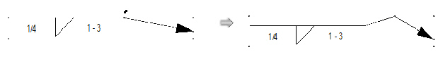
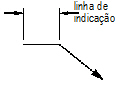
A ferramenta Linha de Indicação Simples insere duas linhas conectadas, formando uma linha de ombro e uma linha de indicação.
Modo |
Descrição |
|---|---|
Restrita |
Restringe a linha de ombro e a linha de indicação a serem verticais, horizontais, 30°, 45°, ou 60° ao clicar ponto |
Livre |
Desenha cada linha em qualquer ângulo. Pressione e segure a tecla Shift para atrair a linha a ângulos predeterminados. |

Para criar uma linha de indicação nas configurações Fundamentals:
1 Clique na ferramenta Linha de Indicação Simples da paleta ferramentas Básicas e selecione o modo Constrained ou Livre Constrained da barra de Ferramentas.
2 Clique para definir o inicio da linha de ombro; clique para definir o fim do ombro e inicio da linha de indicação.
3 Clique novamente para definir o ponto final da linha de indicação.

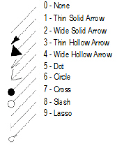
Por definição, um marcador seta preenchida é posicionado ao fim da linha de indicação. Um marcador diferente pode ser selecionado na paleta Atributos (veja “Marker Attributes” on page 1219).
 Inserindo
uma Linha de Indicação Design Series
Inserindo
uma Linha de Indicação Design Series 
Para criar uma linha de indicação em uma configuração Design Series:
1 Clique na ferramenta Linha de Indicação da paleta ferramentas Básicas.
2 Clique para posicionar o objeto no desenho, e clique novamente para configurar a rotação.
A primeira vez que você utilizar a ferramenta em um arquivo, uma janela de diálogo propriedades abrirá. Configure as propriedades padrões, e clique OK. As propriedades podem ser editadas a partir da paleta informações de Objeto.
Clique para exibir/ocultar os parâmetros.
Após o posicionamento, os pontos de controle no marcador e no ombro permitem que a linha de indicação seja reposicionada.
Se existirem muitos objetos linha de indicação, utilize o comando Alinhar/Distribuir Linhas de Indicação para melhorar a legibilidade.
~~~~~~~~~~~~~~~~~~~~~~~~~
Várias ferramentas no produto Vectorworks Fundamentals adiciona informação de conjunto a um desenho com objetos preformatados. O produto Vectorworks Design Series oferece ferramentas para objetos de anotações acicionais.
~~~~~~~~~~~~~~~~~~~~~~~~~
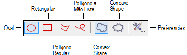
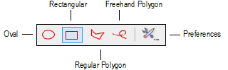
Use a ferramenta de Balões de Revisão para identificar uma seção do desenho que mudou. Insira um balão de revisão em uma área do desenho, ou ao redor de uma porção inteira do desenho, se apropriado.
Para os produtos Vectorworks Design Series, balões de revisão podem também ser criados primeiramente desenhando uma polilinha e então selecionando “Creating Objects from Shapes” na página 273).
Modo |
Descrição |
|---|---|
Oval |
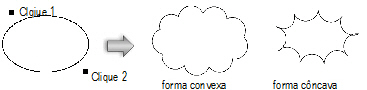
Insere o balão de revisão em volta do perímetro da oval prevista. Clique para ajustar o ponto inicial, mova o cursor na direção desejada, e clique para colocar o ponto final. Limite a oval a 45 graus para desenhar um círculo.
|
Retangular |
Insere o balão de revisão em volta do perímetro do retângulo previsto. Clique para ajustar o ponto inicial, mova o cursor na direção desejada, e clique para colocar o ponto final. Limite a oval a 45 graus para desenhar um quadrado.
|
Polígono Regular |
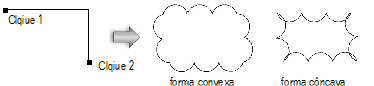
Insere o balão de revisão ao redor do perímetro dos vértices especificados. Clique para posicionar o ponto de partida (primeiro vértice), clique na posição desejada para cada um dos vértices subsequentes, e ou clique no primeiro vértice para fechar o polígono ou faça um duplo clique no último vértice para criar um polígono aberto. Se o polígono for aberto, o balão de revisão será completado com base no contorno.
|
Polígono a Mão Livre |
Insere o balão de revisão ao redor do perímetro dos vértices especificados. Clique para posicionar o ponto inicial e clique-arraste para desenhar o polígono a mão livre. Se o polígono for aberto, o balão é completado com base no contorno.
|

Para criar um balão de revisão:
1. Clique na ferramenta Balão de Revisão do conjunto de ferramentas Cotas/Anotações.
2. Clique o botão de Preferências na barra de Ferramentas para definir as propriedades do balão de revisão. As propriedades podem ser também ajustadas após colocação, a partir da paleta Informações do Objeto. Clique OK.
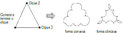
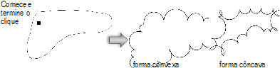
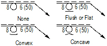
3. Selecione o modo balão de revisão e selecione para desenhar o balão com forma convexa ou côncava. A forma convexa desenha curvas para fora da imagem prevista ou dos vértices especificados. A forma côncava desenha curvas para dentro da imagem prevista ou dos vértices especificados.
4. Clique para desenhar o balão de revisão de acordo com o modo especificado.
Clique para mostrar/ocultar os parâmetros.
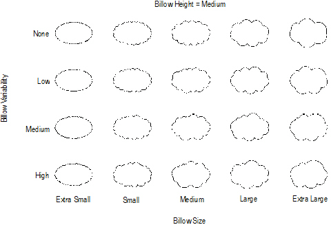
A ilustração seguinte demonstra o efeito de variar os parâmetros de tamanho e variação da curva.
~~~~~~~~~~~~~~~~~~~~~~~~~
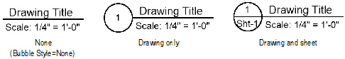
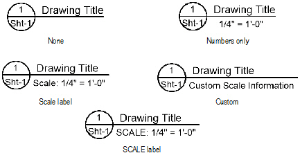
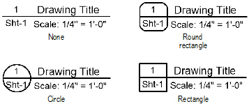
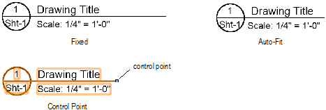
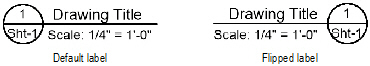
Use a ferramenta Rótulo do Desenho para adicionar informações descritivas a um desenho. Por padrão, um objeto de rótulo inclui um título, a escala do desenho e um número atribuído automaticamente. O número da folha que contém o desenho pode também ser incluído na etiqueta. Os valores padrão para o título, número do desenho, e número da folha depender de onde o rótulo é colocado: em uma camada design, ou em uma anotação de janela de exibição, por exemplo.
Rótulos de desenho mantem um tamanho constante independentemente da escala do desenho.

Para criar um rótulo do desenho:
1 Clique na ferramenta de Rótulo do Desenho a partir do conjunto de ferramentas Cotas/Anotação.
2 Clique para colocar o objeto no desenho, e clique novamente para definir a rotação.
A primeira vez que você usar a ferramenta em um arquivo, uma caixa de diálogo Propriedades é aberta. Defina as propriedades padrão e clique em OK.As propriedades podem ser editadas a partir da paleta Informações do Objeto.
Clique para mostrar/ocultar os parâmetros.
~~~~~~~~~~~~~~~~~~~~~~~~~
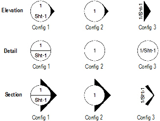
Use the Reference Marker tool to indicate the drawing number and sheet number of a referenced drawing, in a variety of configurations.
Reference markers maintain a constant size regardless of the drawing scale.

To create a reference marker:
1 Click the Reference Marker tool from the Dims/Notes tool set.
2 Click to place the object in the drawing, and click again to set the rotation.
The first time you use the tool in a file, a properties dialog box opens. Set the default properties, and click OK. The properties can be edited from the Object Info palette.
Click to show/hide the parameters.
~~~~~~~~~~~~~~~~~~~~~~~~~
Use the Data Stamp tool to indicate the date, time, and file name of the current drawing, in a variety of configurations.

To create a data stamp:
1 Click the Data Stamp tool from the Dims/Notes tool set.
2 Click to place the object in the drawing, and click again to set the rotation.
The first time you use the tool in a file, a properties dialog box opens. Set the default properties, and click OK. The properties can be edited from the Object Info palette.
Click to show/hide the parameters.
Click here for a video tip about this topic (Internet access required).
~~~~~~~~~~~~~~~~~~~~~~~~~
 Creating North
Arrows
Creating North
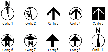
Arrows Use the North Arrow tool to indicate the drawing orientation, in a variety of configurations. The deviation from true magnetic north can be displayed on some of the configurations. If the design layer is georeferenced, the object is rotated to point in the proper direction.
North arrows maintain a constant size regardless of the drawing scale.

To create a north arrow:
1 Click the North Arrow tool from the Dims/Notes tool set.
2 Click to place the object in the drawing, and click again to set the rotation.
The first time you use the tool in a file, a properties dialog box opens. Set the default properties, and click OK. The properties can be edited from the Object Info palette.
Click to show/hide the parameters.
~~~~~~~~~~~~~~~~~~~~~~~~~
 Creating Revision
Markers
Creating Revision
Markers Use the Revision Marker tool indicate the drawing revision number.
Revision markers maintain a constant size regardless of the drawing scale.

To create a revision marker:
1 Click the Revision Marker tool from the Dims/Notes tool set.
2 Click to place the object in the drawing, and click again to set the rotation.
The first time you use the tool in a file, a properties dialog box opens. Set the default properties, and click OK. The properties can be edited from the Object Info palette.
Click to show/hide the parameters.
~~~~~~~~~~~~~~~~~~~~~~~~~
 Creating Elevation
Benchmarks
Creating Elevation
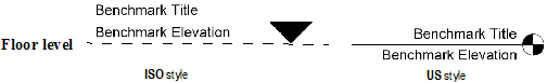
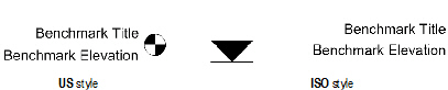
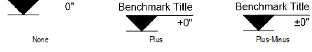
Benchmarks Use the Elevation Benchmark tool to indicate the height of an object in an elevation drawing. Two elevation benchmark styles are available: ISO and US.

To create an elevation benchmark:
1 Click the Elevation Benchmark tool from the Dims/Notes tool set.
2 Click to place the object in the drawing, and click again to set the length and rotation.
The first time you use the tool in a file, a properties dialog box opens. Set the default properties, and click OK. The properties can be edited from the Object Info palette.
Click to show/hide the parameters.
After creation, multiple elevation benchmark objects can be aligned and distributed with the Align/Distribute Leader Lines command; see “Aligning and Distributing Leader Lines” on page 1149.
~~~~~~~~~~~~~~~~~~~~~~~~~
 Indicating the
Slope of Surfaces
Indicating the
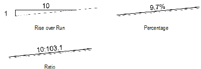
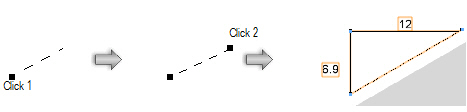
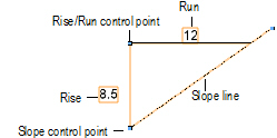
Slope of Surfaces Use the Slope Dimension tool to indicate the slope of any angle that is perpendicular to the screen.

To create a slope indicator:
1 Click the Slope Dimension tool from the Dims/Notes tool set.
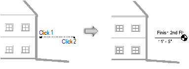
2 Click to mark the beginning of the slope. Click again to mark the end of the slope.
The first time you use the tool in a file, a properties dialog box opens. Set the default properties, and click OK. The properties can be edited from the Object Info palette.
Click to show/hide the parameters.
~~~~~~~~~~~~~~~~~~~~~~~~~
Use the Scale Bar tool to indicate the scale of the drawing objects. To include a scale bar for a viewport, select Modify > Edit Viewport, and place the scale bar as a viewport annotation.
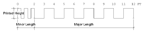

To create a scale bar:
1 Click the Scale Bar tool from the Dims/Notes tool set.
2 Click to place the object in the drawing, and click again to set the rotation.
The first time you use the tool in a file, a properties dialog box opens. Set the default properties, and click OK. The properties can be edited from the Object Info palette.
Click to show/hide the parameters.
~~~~~~~~~~~~~~~~~~~~~~~~~
 Creating Grid
Bubbles
Creating Grid
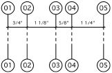
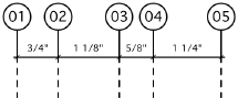
BubblesGrid bubble objects are dimensioned grid lines with bubble markers. This type of drawing notation can help locate columns and other primary building features on construction documents.
Grid marker objects maintain a constant size regardless of the drawing scale.

To create a grid bubble:
1 Click the Grid Bubble tool from the Dims/Notes tool set.
Place a line of grid bubbles by drawing an open polygon with the tool. The first click starts the grid line; the second click determines the angle of the grid line and sets a marker at that location. Each remaining click sets a grid marker.
2 Double-click to end the grid line.
The first time you use the tool in a file, a properties dialog box opens. Set the default properties, and click OK. The properties can be edited from the Object Info palette.
Click to show/hide the parameters.
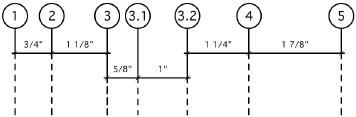
Combine several bubble grids and adjust the labeling properties to create hierarchical (nested) grids.
~~~~~~~~~~~~~~~~~~~~~~~~~
In some drawing standards, when drawing a building or object that is in complete symmetry, the designer may draw only half of the model and insert a symmetry label to indicate the symmetry line.
Symmetry labels maintain a constant size regardless of the drawing scale.

To create a symmetry label:
1 Click the Symmetry Label tool from the Dims/Notes tool set.
2 Click to place the object in the drawing, and click again to set the length and rotation.
~~~~~~~~~~~~~~~~~~~~~~~~~
 Error/Revision Management Using
Redlines
Error/Revision Management Using
RedlinesUse the Redline tool and commands to annotate drawings with redlines and sketches, and to keep track of redline objects and any corrections and revisions that occur in a drawing.
~~~~~~~~~~~~~~~~~~~~~~~~~
 Placing Redlines
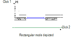
 Use the Redline tool to create redline objects, which are graphical time-stamped change requests on the drawing.
Several modes are available.

To redline an object or area:
1 Click the Redline tool from the Dims/Notes tool set, and select a drawing mode from the Tool bar.
2 Click Preferences from the Tool bar to specify the Redline tool parameters for this session.
The Place Redline dialog box opens.
Click to show/hide the parameters.
3 Click OK.
4 On the design layer where the revision is to be performed, draw the redline around the revision area.
Based on the selected creation method, the appropriate tool creates the redline. This allows the use of SmartCursor cues, object snapping, and boomerang mode when drawing redlines.
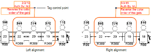
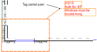
5 The Place Redline dialog box opens. Enter the redline information and authorization.
Click to show/hide the parameters.
6 Click OK.
The redline object indicates the current date and the drawing condition to be corrected. Position redline text by clicking on the tag control point and dragging the tag to the desired location. If there are several redline objects, use the Align/Distribute Leader Lines command to improve readability (see “Aligning and Distributing Leader Lines” on page 1149).
The parameters of one or more selected redline objects can be edited from the Object Info palette.
Click to show/hide the parameters.
~~~~~~~~~~~~~~~~~~~~~~~~~
 Attaching a Sketch to a Redline
In screen plane mode, one or more selected objects can be attached to a redline object to illustrate the redline comments. The object to be attached as a sketch must be selected before drawing the redline; this process converts the selected object to a sketch symbol and places it in a Redline Sketches symbol folder saved with the file.

To attach a selected object as a redline sketch:
1 Switch to the screen plane (see “Planar Modes of 2D Objects: Screen Plane and Layer Plane” on page 168).
2 Select the object to be converted to a sketch.
3 Click the Redline tool from the Dims/Notes tool set, and draw the redline as described in “Placing Redlines” na página 1251.
The Place Redline dialog box opens.
4 Select Attach the current selection as a sketch and click OK.
5 The selection is converted to a symbol that is attached to and moves with the redline object.
The sketch can be hidden by deselecting Show Sketch from the Object Info palette.
~~~~~~~~~~~~~~~~~~~~~~~~~
 Show or
Hide Redlines
Show or
Hide Redlines Over the course of a project, most drawings receive a large number of redlines, which, if left visible, would clutter the drawing. Select Text > Redlines > Show or Hide Redlines to toggle redline visibility.
All Redline objects are drawn in the Notes-Redlines class. If redlines are hidden when a new redline is drawn, the Notes-Redlines class visibility is automatically turned on and all the redlines become visible. Use the Show or Hide Redlines command to hide them again.
~~~~~~~~~~~~~~~~~~~~~~~~~
 Pick up
Redline
Pick up
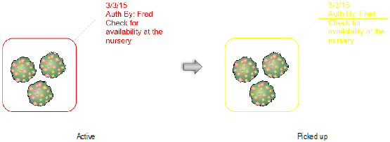
Redline Once the change or correction indicated by the redline has been resolved, one or more redlines can be “picked up” or changed to a closed state.
To pick up a redline:
1 Select the redline.
2 Select Text > Redlines > Pick Up Redline.
Alternatively, right-click (Windows) or Ctrl-click (Mac) the redline and select Pick Up Redline from the context menu.
The status of all selected redline objects changes to closed. The redline color changes from red to yellow, and the pick-up date is set.
Redlines can also be picked up by selecting one or more redline objects and selecting Picked Up from the Object Info palette.
~~~~~~~~~~~~~~~~~~~~~~~~~
 Restore Redline
 Selected closed redline objects can be restored to an open status. A redline object may need to be restored when a revision has not been performed satisfactorily.
To change the state of a closed redline back to open:
1 Select the redline.
2 Select Text > Redlines > Restore Redline.
Alternatively, right-click (Windows) or Ctrl-click (Mac) the redline and select Restore Redline from the context menu.
The selected redlines are returned to an open status and the redline color changes back to red. The original redline creation date is displayed. Redlines can also be restored by selecting one or more redline objects and deselecting Picked Up from the Object Info palette.
~~~~~~~~~~~~~~~~~~~~~~~~~
 Redline Status
Worksheet
Redline Status
Worksheet The redline worksheet lists the status of all redlines in the current file. The Open Redlines section lists all redlines that require resolution; the Closed Redlines section shows all resolved redlines. For each redline item, the design layer location, date, and redline comment displays.
To create or open the redline status worksheet:
1 Select Text > Redlines > Create Redline Status WS.
2 The Redlines Status Report worksheet is created and opens automatically. It is added to the Window > Worksheets menu and it is listed in the Resource Browser.
Redlines, both open and closed, are listed in the report even if they are currently hidden.
~~~~~~~~~~~~~~~~~~~~~~~~~
 Using the
ID Label Tool
Using the
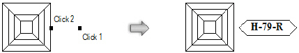
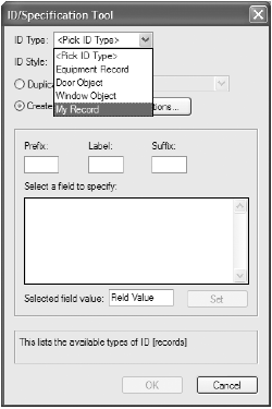
ID Label Tool The ID Label tool labels drawing objects with an identifier so they can be properly referenced on an associated schedule. These labels can be applied to specific objects with attached data records, such as doors, windows, equipment, plumbing fixtures, electrical items, and irrigation objects. This tool also provides a convenient way to specify or edit attached record data. The ID labels can be customized using special symbols (see “Creating Custom ID Label Symbols” na página 1260 for more information).
For doors and windows, the ID label bubble size is independent of text size. The ID bubble is drawn at the size specified in the ID Label Size field of the Object Info palette, unless the text exceeds the ID bubble size; in this case, the bubble automatically expands to fit the text. To restore the ID bubble to a fixed size, reduce the text size to fit within the ID bubble.

To create an ID label:
1 Click the ID Label tool from the Dims/Notes tool set.
2 Click on the drawing to set the location of the ID label.
3 Click a valid object (with attached data records).
The ID/Specification Tool dialog box opens. Set the ID parameters.
Click to show/hide the parameters.
4 Click Options to set specific preferences for this ID.
• If the object being labeled is a window or door, complete the fields in the ID Settings dialog box as described in the ID Tag tab section of “Window Settings: ID Tag Pane” on page 677 or “Door Settings: ID Tag Pane” on page 702. Select Auto-Increment ID Label to automatically increment the numerical ID value each time the label is placed. Click OK.
• If the object being labeled is something other than a window or door, complete the fields in the Set ID Preferences dialog box, and then click OK.
Click to show/hide the parameters.
5 Click OK to close the ID/Specification Tool dialog box and create the label.
To bypass the ID Label dialog boxes and automatically place an existing ID label repeatedly, hold down the Alt (Windows) or Option (Mac) key when placing consecutive labels.
To easily convert an object into a door or window, place an ID label on the object and select the Window Object or Door Object ID Type in the ID/Specification Tool dialog box. A symbol is automatically created for the object and displays in the Resource Browser, and is available to use as symbol geometry for subsequently placed windows or doors. Select the window or door object and then click Settings from the Object Info palette. From the Window Settings or Door Settings dialog box, attach record information to include in the window or door schedule. (See “Inserting Windows in Vectorworks Design Series” on page 674 and “Inserting Doors in Vectorworks Fundamentals” on page 691.)
~~~~~~~~~~~~~~~~~~~~~~~~~
 Editing
Existing ID Labels and Record Information
Editing
Existing ID Labels and Record InformationAfter placement, objects with record information and ID labels can be edited to change the record or ID data. Worksheets, including schedules, and the ID Label tool can change the record information of multiple objects at once.
Global changes to symbol and plug-in object record information can be made using database rows in worksheets created with the Vectorworks program. During a schedule review, it is often necessary to make changes to objects and update them automatically on the drawing.
Only database rows are directly associated with drawing elements, and can update the drawing in this way. Fields which result from a calculation, or from locked objects, workgroup-referenced items, or control points, cannot edit drawing elements. For more information on worksheets, see “Using Worksheets” on page 1446.
To edit record information from a worksheet:
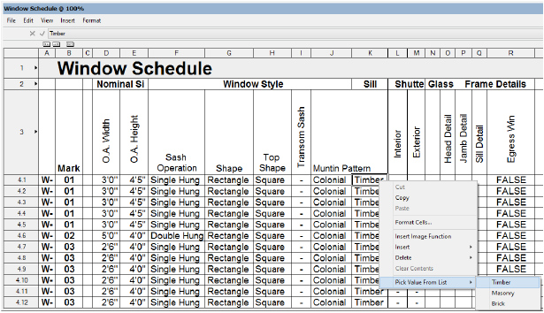
1 Open the worksheet that contains the record information to be edited, by selecting the worksheet in the Resource Browser and selecting Edit from the Resources menu or the context menu. Alternatively, select the worksheet from the Window > Worksheets menu.
For example, a Window Schedule worksheet contains record information for the windows in the drawing.
2 Select the database row cell to be edited.
Text and number fields can be edited directly, while popup fields allow a selection to be made, either from the edit list at the top of the worksheet, or from the Pick Value from List context menu item.
To repeat the same value in several text or number fields of the same record, copy the desired value from one field, select multiple rows, and paste. (Pasting cannot be performed for popup fields.)
3 The drawing records automatically update with the new information, and the drawing objects reflect the changes.
If record field from a summarized database row has been edited, all objects referenced by the row are edited.
The ID Label tool can be used to change ID or record information after an ID is placed. Labels and records for styled walls are edited differently; see “Editing ID Labels and Records for Wall Styles” na página 1259 for details.

To edit an existing ID label or record information:
1 Click the ID Label tool from the Dims/Notes tool set.
2 Double-click the ID label to edit.
• If the labeled object is a window or door, complete the fields as described in the Data tab section of “Window Settings: Data Pane” on page 687 or “Door Settings: Data Pane” on page 712. If you edit the object through the Object Info palette, an additional parameter, ID Label Size, is available for controlling the size of the ID label bubble.
• If the labeled object is something other than a window or door, edit the fields in the ID/Specification Tool dialog box, as described in “Using the ID Label Tool” na página 1256.
3 Click OK.
The edits are applied to the ID label and record attached to the object.
Data fields (including an ID label) are specified for each wall style, which means that each wall with a particular style has the same label and record attached to it. Therefore, ID labels and records cannot be edited for individual styled walls with the ID Label tool. (See “Using Wall Styles” on page 568 for more information about creating, editing, and using wall styles.)
To edit ID label or record information for a wall style:
1 Select the wall style from the Resource Browser and click Edit from the Resources menu.
2 In the Edit Wall Style dialog box, click the Data Fields tab.
3 Enter a label ID in the Mark field, and enter other data fields as necessary.
4 Click OK to close the Edit Wall Style dialog box, and click OK again to close the Wall Replacement dialog box.
From this point forward, walls that are created with this style have the specified data record attached; when an ID label is added to a wall that has this style, the Mark entry displays in the label.
 Vectorworks
Architect and Landmark ID Symbols
Vectorworks
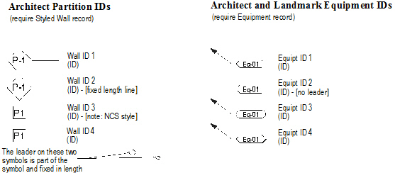
Architect and Landmark ID Symbols The following ID symbols are provided with the Vectorworks Architect and Landmark products, and require the presence of the indicated record format in the drawing file. The ID Label tool creates the record format if it does not already exist.
~~~~~~~~~~~~~~~~~~~~~~~~~
 Creating
Custom ID Label Symbols
Creating
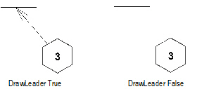
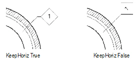
Custom ID Label SymbolsThe Vectorworks Architect and Landmark ID labels are created as plug-in objects that draw an ID symbol and an optional leader line. The symbols can automatically be kept horizontal, or can be rotated to the leader line angle.
It is possible to create ID symbols based on custom markers. ID symbols have certain requirements that must be met.
The ID Label tool (see “Using the ID Label Tool” na página 1256) detects the presence of any existing record information for the object being labeled in the drawing; if the tool cannot detect record information, you are prompted to select the appropriate record from a list. The ID symbols defined to work with that record type display for selection.
The ID Label tool determines whether the ID symbol requested in the dialog box is present in the drawing. If not, it copies it in from the ID_Symbols.vwx file, and scales it to the current drawing layer scale. Once an appropriate scaled symbol is created, it is used without further reference to external documents.
ID symbols must meet the following requirements:
• Stored in the Vectorworks library file [Vectorworks]\Plug-Ins\Common\Data\ID_Symbols.vwx
• Created at a 1:1 scale, using certain graphic primitives
• Use linked text to display ID and attribute information
• Have a TagSchema record attached
The TagSchema record determines the behavior of the ID symbol text. This record is present in the ID_Symbols.vwx file.

The AutoIncrement, FixCurrRecord, WriteMatchIDs, DrawLeader, and KeepHoriz fields are Boolean (true/false) values; ShoulderLength and MkrScaleFactor are numerical values. All other fields are text values.
Four TagSchema record fields determine whether the ID symbol is drawn with a leader, and, if so, determine the leader’s appearance.
Click to show/hide the parameters.
The ID record writing options are controlled by four fields in the TagSchema record:
Click to show/hide the parameters.
The ID symbol can have up to seven fields containing virtually any text, combined with the contents of the data record the ID uses.
For example, the ID Label tool reads the contents of the Fld1Spec field and writes the results to the Fld1Text field. The “Spec” field follows the format FieldName& “string constant” where the field names are fields in the data record named in the TagType field; the & indicates a concatenation, and the string constants are surrounded by double quotes.
For example, a field in the data record is called “Count.” This is a number field representing the total number of something. You want the first field in the ID to read: TOTAL: 12 when “Count” is 12. Enter the following formula in the Tag1Spec field: “TOTAL: ”&Count. There are no spaces between the ampersand and the field name, or between the string constant (in quotes) and the ampersand.
You can concatenate any number of fields and constants. For example, you could add the word “Item” to the tag field definition by using the following formula: “TOTAL: ”&Count& “ Item”.
There are a variety of pre-defined fields in the ID symbols that come with the Vectorworks Architect and Landmark products. Use these as a guideline in understanding this special formula language. This same formula convention is also used to define HVAC object tags.
If the ID Label tool cannot find the data record specified in the TagType field of the TagSchema record, the error message #RECORDNAME?# displays when the ID is placed. If any of the fields in the formula are misnamed, the message #FIELDNAME?# displays in the affected ID field. Verify the spelling of record and field names and ensure the data record is defined as described in “The Data Record” na página 1263.
The data record named in the TagType field of the ID symbol should be part of the standard records created using the VA Records and Schedules command and should be present in the current preference set. This enables the ID Label tool to create the record automatically if it is not defined at the time the ID Label tool is used.
The TagType “Styled Wall” is reserved for use when an ID is placed on a styled wall.
~~~~~~~~~~~~~~~~~~~~~~~~~
 Creating
Custom ID Symbols
Creating
Custom ID SymbolsKeeping in mind the information described in “Understanding ID Labels” na página 1260, it is possible to create a custom ID symbol to be used by the ID Label tool.
An ID symbol can consist of any 2D object supported in the Vectorworks program except circles, arcs, grouped objects, or other symbols. These guidelines are necessary for the scaling algorithm currently used by the ID Label tool, to scale the symbol to the correct scale for the file. To achieve the look of an arc in the symbol, use an arc-smoothed vertex of a polyline; use an oval instead of a circle.
To create a custom ID symbol:
1 Open the ID Symbols.vwx file, located in the Vectorworks application folder [Vectorworks]\Plug-Ins\Common\Data.
The TagSchema record, as well as the ID symbols currently used by the ID Label tool, are present in this file.
2 At a 1:1 scale, draw the object representing the ID symbol.
3 Select Modify > Create Symbol to create a symbol from the object (see “Creating New Symbols” on page 275 for more information on creating symbols).
4 Select the new symbol in the Resource Browser and select Edit from the Resources menu.
The Edit Symbol dialog box opens.
5 Select the 2D Component and click Edit to open the Edit Symbol window.
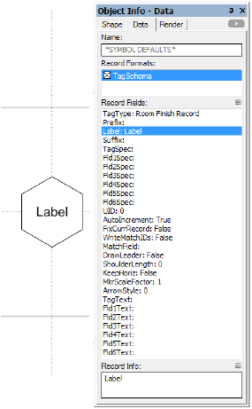
6 Deselect all items by clicking in an empty area.
On the Data tab of the Object Info palette, *SYMBOL DEFAULTS* is displayed.
7 Attach the Tag Schema record by selecting it from the Data tab.
8 An “X “displays in the check box.
9 Select the TagType field and replace the field name with the exact name of your custom record.
10 Create and format text to be used to display the ID symbol text.
For more information, see “Linking Text to Record Formats” on page 306.
11 With the text selected, select Tools > Records > Link Text to Record.
The Choose Field dialog box opens.
12 In the Tag Schema record format, select the Label field and click OK.
13 The symbol text is linked to display the contents of the Label record field.
To check the text link, enter text in the Label field on the Data tab of the Object Info palette. Data entered now would be overwritten later, in any case, by the ID Label tool.
14 Click Exit Symbol at the top right corner of the window to return to the drawing.
15 In the Pally script palette, double-click the Output ID Prefs script to run it.
16 Save the ID_Symbols.vwx file.
17 In the drawing file where the custom ID symbol is to be used by the ID Label tool, ensure that a record format exists which exactly matches the record name entered previously in the TagType field.
18 Click the ID Label tool from the Dims/Notes tool set.
The ID/Specification Tool dialog box opens.
19 The custom record is one of the selections for ID Type. Select it to use the associated custom ID symbol and click OK.
 Creating Section
Notes
Creating Section
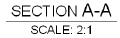
Notes Use the Section Note tool to annotate the drawing or detail with section letters, and, if desired, a scale. Use the Format Text command to edit the text attributes.

To create a section note:
1 Click the Section Note tool from the Dims/Notes tool set.
2 Click to place the object in the drawing, and click again to set the rotation.
The first time you use the tool in a file, a properties dialog box opens. Set the default properties, and click OK. The properties can be edited from the Object Info palette.
Click to show/hide the parameters.
 Creating Material
Notes
Creating Material
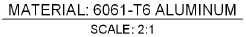
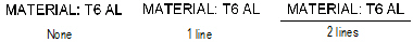
Notes Use the Material Note tool to annotate the drawing or detail with material composition, and, if desired, scale. Use the Format Text command to edit the text attributes.

To create a material note:
1 Click the Material Note tool from the Dims/Notes tool set.
2 Click to place the object in the drawing, and click again to set the rotation.
The first time you use the tool in a file, a properties dialog box opens. Set the default properties, and click OK. The properties can be edited from the Object Info palette.
Click to show/hide the parameters.
 Creating Center
Line Markers
Creating Center
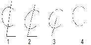
Line Markers Use the Center Line Marker tool to indicate the center line on a drawing.

To create a center line marker:
1 Click the Center Line Marker tool from the Dims/Notes tool set.
2 Click to place the object in the drawing, and click again to set the rotation.
The first time you use the tool in a file, a properties dialog box opens. Set the default properties, and click OK. The properties can be edited from the Object Info palette.
Click to show/hide the parameters.
 Creating
Detail Bubbles
Creating
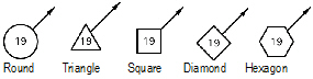
Detail BubblesA detail bubble assigns a detail number to the parts of an assembly drawing.
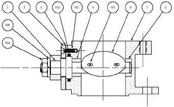
The information associated with the detail bubble can be used to create both parts lists and bill of materials lists.
~~~~~~~~~~~~~~~~~~~~~~~~~
 Adding Detail
Bubbles
Adding Detail
Bubbles 
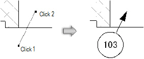
To create a detail bubble:
1 Click the Detail Bubble tool from the Dims/Notes tool set.
2 Click to place the object in the drawing, and click again to set the length and rotation of the leader line.
The first time you use the tool in a file, a properties dialog box opens. Set the default properties, and click OK. The properties can be edited from the Object Info palette.
If no Part Info record exists, one is created automatically the first time a detail bubble is placed in the drawing.
The detail bubble number automatically increments as the bubbles are placed. Change the auto-incrementing number by editing the Item Number field from the Object Info palette. When detail bubble placement resumes, the last number entered becomes the starting number.
~~~~~~~~~~~~~~~~~~~~~~~~~
 Detail Bubble Record Format
The Part Info record format stores the information for the detail bubble. This record format can be edited to add new fields or to delete existing fields. To edit the record format, right-click the record format in the Resource Browser and select Edit. For more information on record formats, see “Record Formats” on page 300.
If new fields are created, the existing Bill of Materials and Parts List worksheets need to be modified to reflect the changes. Alternatively, create new worksheets to accommodate the new fields. For more information on using worksheets, see “Using Worksheets” on page 1446.
~~~~~~~~~~~~~~~~~~~~~~~~~
 Editing Detail Bubbles
Edit the detail bubble properties from the Object Info palette.
Click to show/hide the parameters.
Once the detail bubble has been placed, its marker can be selected from the Attributes palette (see “Marker Attributes” on page 1219).
To edit the record information associated with a detail bubble:
1 Select the bubble, and then click Change Bubble Info from the Object Info palette.
The Edit Detail Bubble dialog box opens.
2 Enter the information associated with the detail bubble. The information can be used to complete the parts list and bill of materials worksheets.
3 Click OK to return to the Object Info palette. If the Item # was changed, the change is automatically made to the Object Info palette and the object.
~~~~~~~~~~~~~~~~~~~~~~~~~
 Creating
a Bill of Materials
Creating
a Bill of Materials The information associated with the detail bubbles can be included in a worksheet which automatically generates a bill of materials list.
To create a bill of materials:
1 Once the detail bubble record information has been completed, select the Create Bill of Materials command from the appropriate menu:
• Architect workspace: AEC > Machine Design > Create Bill of Materials
• Landmark workspace: Landmark > Machine Design > Create Bill of Materials
• Spotlight workspace: Spotlight > Machine Design > Create Bill of Materials
2 With the bull’s-eye cursor, click in the drawing to place the worksheet.
Alternatively, from the Resource Browser, select Vectorworks Libraries from the Files list, and open the Defaults\Sheet Border - Title Blocks folder. Open the appropriate title blocks file, and then drag the Bill of Materials worksheet object from the Resource Browser to place the worksheet graphic object in the drawing.
3 Double-click the worksheet, or select Window > Worksheets > Bill of Materials, to open the worksheet. From the Worksheet menu, select Recalculate. The record information from the detail bubbles automatically fills the worksheet, and all calculations are performed. For more information on worksheets, see “Using Worksheets” on page 1446.
4 Close the worksheet. The worksheet graphic object on the drawing reflects the changes.
5 Reopen the worksheet and select Recalculate from the Worksheet menu to update the worksheet when any changes are made to the record information.
A parts list can be added to an ASME title block; see “Sheet Border Properties” on page 94.
~~~~~~~~~~~~~~~~~~~~~~~~~
 Creating a
Parts List
Creating a
Parts List The information associated with the detail bubbles can be included in a worksheet that automatically generates a parts list.
To create a parts list:
1 Once the detail bubble record information has been completed, select the Create Parts List command from the appropriate menu:
• Architect workspace: AEC > Machine Design > Create Parts List
• Landmark workspace: Landmark > Machine Design > Create Parts List
• Spotlight workspace: Spotlight > Machine Design > Create Parts List
2 With the bull’s-eye cursor, click in the drawing to place a Parts List worksheet.
Alternatively, from the Resource Browser, select Vectorworks Libraries from the Files list, and open the Defaults\Sheet Border - Title Blocks folder. Open the appropriate title blocks file, and then drag the appropriate parts list worksheet object from the Resource Browser to place the worksheet graphic object in the drawing.
The Parts List-1 worksheet object is formatted to fit the ASME title blocks for ASME A, B, and C and ISO A2, A3, A4, and A5 drawing sizes. The Parts List-2 worksheet object is formatted to fit the ASME title blocks for ASME D, E, and F, and ISO A0 and A1 drawing sizes.
3 Double-click the worksheet, or select Window > Worksheets > Parts List to open the worksheet. From the Worksheet menu, select Recalculate. The record information from the detail bubbles automatically fills the worksheet, and all calculations are performed. For more information on worksheets, see “Using Worksheets” on page 1446.
4 Close the worksheet. The worksheet graphic object on the drawing reflects the changes.
5 Reopen the worksheet and select Recalculate from the Worksheet menu to update the worksheet when any changes are made to the record information.
~~~~~~~~~~~~~~~~~~~~~~~~~
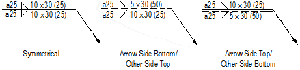
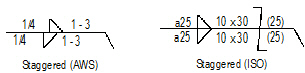
 Welding
and Surface Texture Symbols
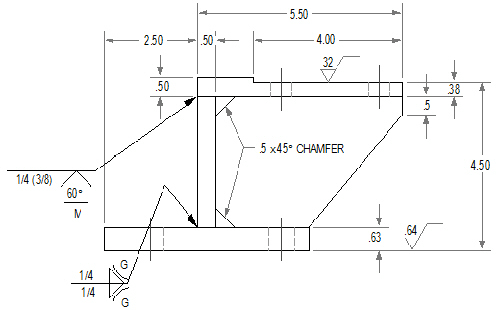
Welding
and Surface Texture SymbolsVectorworks Design Series products contain a comprehensive collection of welding symbols and also include a surface texture symbol. All symbols are placed as point objects.
~~~~~~~~~~~~~~~~~~~~~~~~~
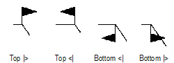
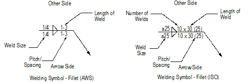
 Fillet Welding
Symbol
Fillet Welding
Symbol
To insert a fillet welding symbol:
1 Click the Welding Sym-Fillet tool from the Dims/Notes tool set.
2 Click to place the object in the drawing, and click again to set the rotation.
The first time you use the tool in a file, a properties dialog box opens. Set the default properties, and click OK. The properties can be edited from the Object Info palette.
3 Once the object has been placed, its marker can be selected from the Attributes palette (see “Marker Attributes” on page 1219).
Click to show/hide the parameters.
~~~~~~~~~~~~~~~~~~~~~~~~~
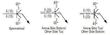
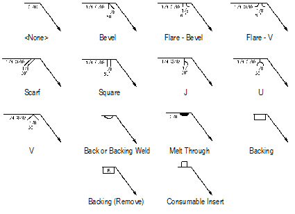
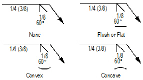
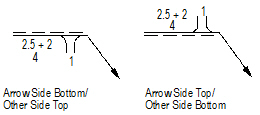
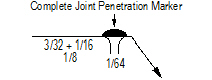
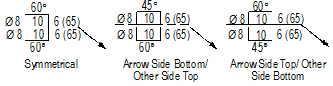
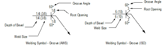
 Groove Welding Symbol
To insert a groove welding symbol:
1 Click the Welding Sym-Groove tool from the Dims/Notes tool set.
2 Click to place the object in the drawing, and click again to set the rotation.
The first time you use the tool in a file, a properties dialog box opens. Set the default properties, and click OK. The properties can be edited from the Object Info palette.
3 Once the object has been placed, its marker can be selected from the Attributes palette (see “Marker Attributes” on page 1219).
Click to show/hide the parameters.
~~~~~~~~~~~~~~~~~~~~~~~~~
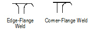
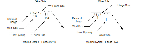
 Flange Welding
Symbol
Flange Welding
Symbol 
To insert a flange welding symbol:
1 Click the Welding Sym-Flange tool from the Dims/Notes tool set.
2 Click to place the object in the drawing, and click again to set the rotation.
The first time you use the tool in a file, a properties dialog box opens. Set the default properties, and click OK. The properties can be edited from the Object Info palette.
3 Once the object has been placed, its marker can be selected from the Attributes palette (see “Marker Attributes” on page 1219).
Click to show/hide the parameters.
~~~~~~~~~~~~~~~~~~~~~~~~~
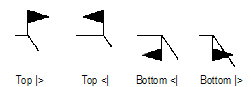
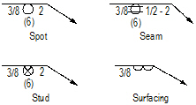
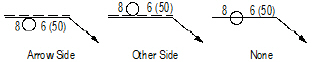
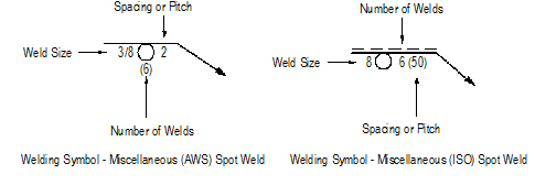
 Miscellaneous Welding
Symbols
Miscellaneous Welding
Symbols 
To insert a miscellaneous welding symbol:
1 Click the Welding Sym-Misc tool from the Dims/Notes tool set to insert a spot, seam, stud, or surfacing welding symbol.
2 Click to place the object in the drawing, and click again to set the rotation.
The first time you use the tool in a file, a properties dialog box opens. Set the default properties, and click OK. The properties can be edited from the Object Info palette.
3 Once the object has been placed, its marker can be selected from the Attributes palette (see “Marker Attributes” on page 1219).
Click to show/hide the parameters.
~~~~~~~~~~~~~~~~~~~~~~~~~
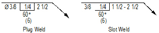
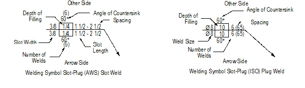
 Slot-Plug Welding
Symbol
Slot-Plug Welding
Symbol 
To insert a slot-plug welding symbol:
1 Click the Welding Sym-Slot-Plug tool from the Dims/Notes tool set.
2 Click to place the object in the drawing, and click again to set the rotation.
The first time you use the tool in a file, a properties dialog box opens. Set the default properties, and click OK. The properties can be edited from the Object Info palette.
3 Once the object has been placed, its marker can be selected from the Attributes palette (see “Marker Attributes” on page 1219).
Click to show/hide the parameters.
~~~~~~~~~~~~~~~~~~~~~~~~~
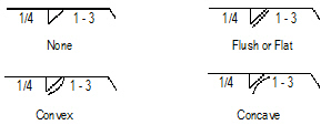
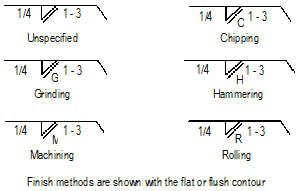
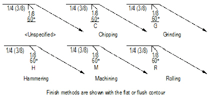
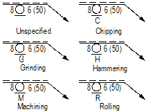
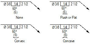
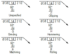
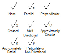
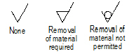
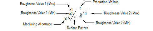
 Surface Texture
Symbol
Surface Texture
Symbol
To insert a surface texture symbol:
1 Click the Surface Texture Symbol tool from the Dims/Notes tool set.
2 Click to place the object in the drawing, and click again to set the rotation.
The first time you use the tool in a file, a properties dialog box opens. Set the default properties, and click OK. The properties can be edited from the Object Info palette.
Click to show/hide the parameters.
~~~~~~~~~~~~~~~~~~~~~~~~~
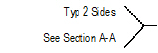
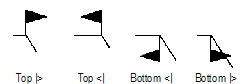
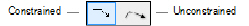
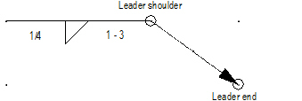
 Editing the Arrow Segment
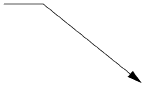
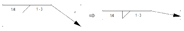
The arrow segment of each welding symbol has two control points for adjusting the segment position.
To move the control points of an arrow segment:
1 Select the welding symbol to edit.
2 Click and hold the leader end control point.
3 Drag the leader end control point to the new location and click to set.
4 Click and hold the leader shoulder control point.
5 Drag the leader shoulder control point to the new location and click to set.