HVACHVAC
The Heating, Ventilating, and Air Conditioning (HVAC) tools and objects available in the Vectorworks Architect product add HVAC ducts and diffusers in a variety of configurations to a drawing. These geometric models can represent a variety of actual items. For example, the diffuser object can have its dimensions and parameters set to develop many differently sized diffusers, including industry standard sizes that can be predefined. The Vertical Elevation parameter can be specified for top and bottom elevations, allowing ducts to be measured from the floor rather than the ceiling.
Access HVAC objects from the Resource Browser; from the Files list, select Vectorworks Libraries. The HVAC objects consist of hybrid 2D/3D representations of common HVAC duct work elements. See “Using the Resource Browser” on page 243.
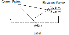
Duct work objects include optionally displayed labels and elevation marker tags. The label contents are determined by a user-defined string of values, such as width and height (obtained automatically) and any text desired. The elevation marker tag indicates the top and bottom distance above the finish floor of an HVAC duct work item; Show 3D Detail must be enabled to display the elevation marker tag. Both the HVAC label and elevation marker tag can be easily moved by dragging its control point to the correct location.
A diffuser report, containing a diffuser, register, and grille schedule, can be included. It can be added to the drawing from the VA Create Schedule command or the Resource Browser. From the Resource Browser, select Vectorworks Libraries from the Files list, and open the default architectural reports file that is included with the Vectorworks Architect product (see “Resource Libraries” on page 239). Drag the Diffuser Report worksheet to the drawing. An HVAC Diffuser, Register and Grille worksheet, populated with information from the objects in the current drawing, is automatically created.
For more information on labels, elevation marker tags, and HVAC reports, refer to the Duct_Object.pdf file included in the Vectorworks application folder [Vectorworks]\Extras.
~~~~~~~~~~~~~~~~~~~~~~~~~
 Electrical and Communication
Circuiting
Electrical and Communication
CircuitingThe communications and electrical circuiting tools and objects available in the Vectorworks Architect product add electrical and communication objects, including panels and disconnects, to a drawing. The circuiting tools link these objects, creating a communication or electrical circuit.
~~~~~~~~~~~~~~~~~~~~~~~~~
 Electrical
and Communication Objects
Electrical
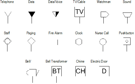
and Communication ObjectsElectrical and communication objects are available from the MEP tool set and in specific object libraries (see “Resource Libraries” on page 239). These objects are accessed through the Resource Browser, and consist of hybrid 2D/3D representations of common electrical devices. These symbols already have the correct records attached for proper circuiting. See “Using the Resource Browser” on page 243.
It is also possible to create custom electrical symbols, panels and disconnects; attaching the correct record to these symbols makes them circuitable. See “Creating Custom Electrical and Communication Symbols” on page 681 for information.
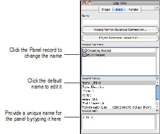
When inserting panels (electrical or communication) from object libraries, give each panel its own name so that it can be uniquely identified by the Circuiting tool.
To identify an inserted panel with a unique name:
1 Insert the panel from the Resource Browser.
2 With the panel still selected, click the Data tab from the Object Info palette. Provide the unique panel name under the Panel record information.
 Circuiting Tool
The Circuiting tool is in the MEP tool set.
Once electrical or communication panels and objects have been inserted, the Circuiting tool links the objects by assigning each item a circuit number and associating it with a panel board.
The symbol or object that is being circuited must be on a visible (not grayed) layer. If the symbol is not on the active layer, the symbol is copied to the active layer, and then the record information is attached. This is designed so that an electrical engineer can use workgroup referencing to access architectural layers with preliminary outlet locations. The engineer can then copy those outlets to the proper layer without re-entering data.
~~~~~~~~~~~~~~~~~~~~~~~~~
 Creating
a Circuit
Creating
a Circuit
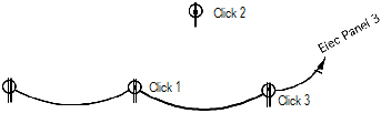
To create a circuit:
1 Click the Circuiting tool from the MEP tool set.
2 Click the first item to be circuited.
If selecting a custom symbol without a Circuiting record attached, the tool attaches the record to the current symbol, as well as to all subsequent symbols in the circuit. In this case, specify whether an electrical or communication circuit is being created.
When creating a circuit, do not include the panel symbol.
Based on the item’s record, the tool determines whether this is an electrical or communication device. The Circuiting Tool dialog box opens.
Click to show/hide the parameters.
3 Enter the desired information for the circuit and the objects in the circuit, and click OK.
The information is transferred to the object’s record.
4 Continue clicking on the items to be circuited in the order the circuit loop should be drawn.
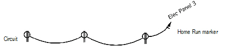
5 To complete the circuit, click in an empty area of the drawing. Confirm that you wish to place the Home Run marker.
The Circuiting tool generates a Home Run marker and phases are denoted as specified.
 Adding
to a Circuit
Adding
to a Circuit
To add an item to an existing circuit:
1 Click the Circuiting tool from the MEP tool set.
2 Click the communication or electrical device from which to begin the new circuit connection.
A notice displays, asking if additional items are to be added to this circuit. Click Yes.
3 Click the item to add to the circuit, and then select the next item in the circuit.
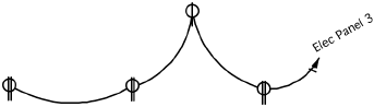
To complete the circuit, click away from any selectable objects. A notice displays asking if you wish to continue. Click No to end this procedure.
If adding an item at the end of a circuit, place the third click anywhere on the drawing. The item is chained to the item that previously had the Home Run marker attached. A notice displays, confirming whether to place the Home Run. Click Yes. The Circuiting tool generates a Home Run marker and phases are denoted.
 Editing Circuits
 The Edit Circuiting tool modifies existing circuit information. Use this tool to reassign circuit numbers and update the information attached to the circuited elements.

To edit existing circuits or a circuited item:
1 Click the Edit Circuiting tool from the MEP tool set.
2 Click the circuited item to be edited.
The Edit Circuit Tool dialog box opens.
Click to show/hide the parameters.
3 Select the operation to perform.
If there are multiple records attached to this item, select the record to edit from the Circuit To Edit list. The record information displays in the Circuit Tool dialog box.
4 Click OK.
 Comm
Device Tool
Comm
Device ToolThe Comm Device tool inserts an indicator and basic specifications to indicate the type and location of a communications device.

To insert a communications device:
1 Select the Comm Device tool from the MEP tool set.
2 Click to place the object into a wall, and click again to set the rotation.
The first time you use the tool in a file, a properties dialog box opens. Set the default properties, and click OK. The properties can be edited from the Object Info palette.
Click to show/hide the parameters.
~~~~~~~~~~~~~~~~~~~~~~~~~
 Sizing
Calculators
Sizing
CalculatorsThe Vectorworks Architect product provides sizing calculators for performing calculations and adding drawing specifications without leaving the program.
The software includes a standard database of wire specifications used for the Conductor Sizing and Conduit Sizing calculators. The database contains the names, dimensions, and physical properties of a selected group of wiring types.
~~~~~~~~~~~~~~~~~~~~~~~~~
 Conductor Sizing
Calculator Command
Conductor Sizing
Calculator CommandThe Conductor Sizing Calculator reports the correct wire size for a given load, based on a single conductor and the length of travel.
To perform conductor sizing calculations:
1 Select AEC > Electrical > Conductor Sizing Calc.
The Conductor Sizing Calculator dialog box opens.
Click to show/hide the parameters.
2 Select the type of calculation to perform, based on the current parameters, from the Calculate list.
Calculation |
Description |
|---|---|
Wire Size |
Provides the sectional area of the wire (cmil) and the approximate AWG for wire sizes below 250 kcmil |
Ohms/ft/cmil-ft |
Calculates the resistance per sectional area of wire |
Voltage Drop |
Calculates the voltage drop across the length of the conductor, either as a percentage or absolute value |
Phase Factor |
Provides the phase factor value of the conductor |
Voltage |
Calculates the voltage value of the conductor |
Ampacity |
Determines the amp rating of the conductor |
Length of Run |
Calculates the allowable length of the conductor specified for the load given |
3 Enter the required values in the fields. Fields where the result will be displayed appear dimmed. Some calculations require the selection of the wire type or manufacturer, as well as the wire size or part number. When all the required parameter values are complete, the Calculate button becomes available; click to perform the calculation.
4 The calculation results are displayed. Select another calculation to perform or click Close to exit.
 Conduit Sizing
Calculator Command
Conduit Sizing
Calculator CommandThe Conduit Sizing Calculator reports the proper size conduit required for a given set of wires.
To perform conduit sizing calculations:
1 Select AEC > Electrical > Conduit Sizing Calc.
The Conduit Sizing Calculator dialog box opens.
Click to show/hide the parameters.
2 When calculations are complete, click Close.
 Creating Piping
Runs
Creating Piping
RunsDetermine the section lengths and amount of material required for piping runs. Piping runs can be drawn by clicking the Piping Run tool from the MEP tool set, by drawing a polygon and selecting the Create Piping Runs command, or by drawing a polyline and selecting the Create Objects from Shapes command (see “Creating Objects from Shapes” on page 301).
To create a piping run:
1 Draw one or more polygons to represent the piping run.
2 With the polygon(s) selected, choose AEC > Electrical > Create Piping Runs.
The piping run results are displayed and can be edited from the Object Info palette. An existing piping run can be reshaped with the Reshape tool, and the path polyline can be edited by selecting Edit from the context menu (see “Object Editing Mode” on page 1056).
Click to show/hide the parameters.
The piping run does not count turns at a junction box (at the location of an electrical object).
 Panel Scheduling
and Diagramming
Panel Scheduling
and DiagrammingThe Create Panel Schedule command generates panel schedules based on the circuiting information assigned to the file. If necessary, modify the dimensions and layout of the panel to conform to existing office standards.
To create a panel schedule:
1 Select Tools > Reports > Create Panel Schedule.
The Create Panel Schedule dialog box opens. Specify the panel schedule criteria and click OK.
Click to show/hide the parameters.
2 If placing the schedule on the drawing, click at the desired location.
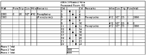
If placing the panel schedule in a worksheet, a worksheet is created with the panel name.
If circuiting changes are made, delete the outdated panel schedule and repeat the create panel schedule procedure.
~~~~~~~~~~~~~~~~~~~~~~~~~
 Changing
the Panel Schedule Format
Changing
the Panel Schedule FormatTo format a panel schedule:
1 Select Tools > Reports > Create Panel Schedule.
The Create Panel Schedule dialog box opens.
2 Select the panel schedule and its location.
3 Click Edit.
4 The Schedule Formatting dialog box opens. Select the schedule to format from the Schedule list. A list of available fields and, if applicable, the schedule’s printed name displays.
Click to show/hide the parameters.
The columns shown in the Column Order list appear in the schedule in order.
Panel schedule formatting is stored as a worksheet named “Panel Schedule Fmt.” This worksheet can be imported, using the Resource Browser, into other files where the same formatting is desired.
5 Click OK to return to the Create Panel Schedule dialog box. Click OK to place the schedule with the specified format.
~~~~~~~~~~~~~~~~~~~~~~~~~
 Creating Panel
Riser Diagrams
Creating Panel
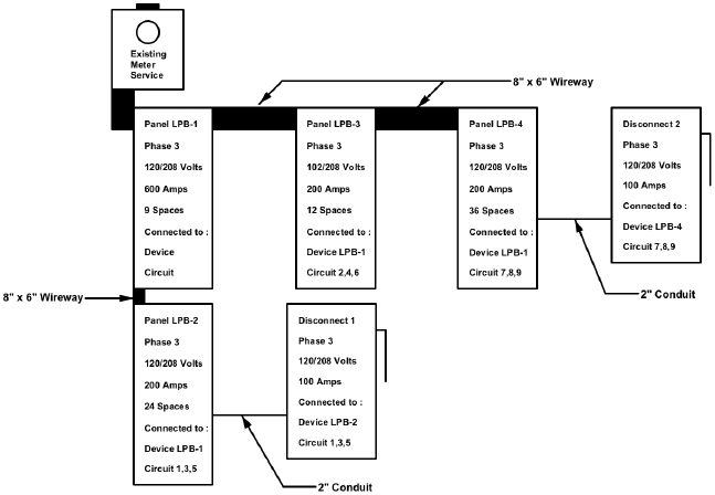
Riser DiagramsPanel riser diagrams summarize the electrical panels and disconnects in a project file.
To create a panel riser diagram:
1 Select Tools > Reports > Create Panel Riser Diag.
2 Click the drawing to place the panel(s) at that location.
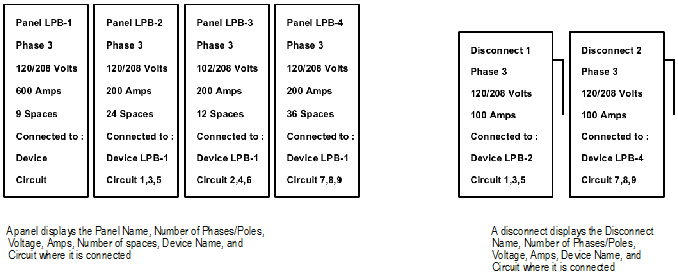
Panels and disconnects can be rearranged, edited and annotated; graphics can be added to complete the panel riser diagram. If the panels are regenerated, any edits are lost. Once the panels have been generated, they can be arranged into a completed panel diagram, as seen in the following illustration:
~~~~~~~~~~~~~~~~~~~~~~~~~
 Creating Custom Electrical and
Communication Symbols
Creating Custom Electrical and
Communication SymbolsThe Vectorworks Architect product includes many pre-defined electrical and communication objects in its object library files. However, there is no need to be restricted to these objects; creating custom panel and circuiting symbols is also possible.
~~~~~~~~~~~~~~~~~~~~~~~~~
 Creating
Custom Panels
Creating
Custom PanelsElectrical, communication, and disconnect panel symbols can be created specifically to fulfill a custom requirement.
To create a panel symbol:
1 Draw the object to represent the panel.
2 Convert the object into a symbol by selecting Modify > Create Symbol. Provide a name for the panel. See “Creating New Resources” on page 249.
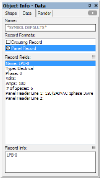
3 The panel symbol requires both a panel and circuiting record. If the file does not contain panel and circuiting records, create the records according to the following formats.
Record names, particularly the Type field names, are case sensitive.
Panel Record
Field |
Type |
Contents |
|---|---|---|
Name |
Text |
Must be unique |
Type |
Text |
Must be Electrical, Communication, or Disconnect |
Phase |
Integer |
1 |
Volts |
Text |
117 |
Amps |
Integer |
100 |
# of Spaces |
Integer |
20 |
Panel Header Line 1 |
Text |
Text placed on Panel Schedule |
Panel Header Line 2 |
Text |
Text placed on Panel Schedule |
Circuiting Record
Field |
Type |
Contents |
|---|---|---|
Name |
Text |
None |
Circuit # |
Integer |
0 |
Wire Size |
Text |
0 |
Trip |
Integer |
0 |
Conduit Size |
Text |
1/2 |
V.A./Watts |
Integer |
0 |
Remarks |
Text |
Panel |
Phase/Pole |
Integer |
2 |
Voltage |
Text |
0 |
Circuit Type |
Integer |
1 for electrical device, 2 for communication device |
UID |
Text |
0 |
ID |
Text |
0 |
4 Select the symbol from the Resource Browser, and then click Edit from the Resources menu.
The Edit Symbol dialog box opens.
5 Click 2D Component, and then click Edit.
6 In the Edit Symbol window, deselect all symbol components.
7 Attach the panel record to the symbol by selecting it from the Data tab from the Object Info palette. Enter the panel information by selecting a record field and entering its record information; the circuiting tools will use this information.
Click to show/hide the parameters.
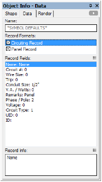
8 Attach the circuiting record to the symbol and enter the circuiting information by selecting a record field and entering its record information; the circuiting tools will use this information.
Click to show/hide the parameters.
9 Click Exit Symbol at the top right of the drawing window.
~~~~~~~~~~~~~~~~~~~~~~~~~
 Creating
Custom Circuit Symbols
Creating
Custom Circuit SymbolsElectrical and communication circuit symbols can be created specifically to fulfill a custom requirement.
To create a circuit symbol:
1 Draw the object to represent the circuitable symbol.
2 Convert the object into a symbol by selecting Modify > Create Symbol. Provide a name for the circuitable item. See “Creating New Resources” on page 249.
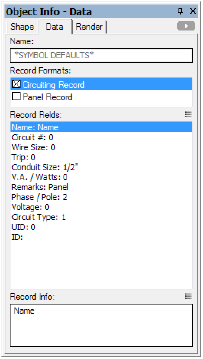
3 If the file does not contain a circuiting record, create the record according to the following format.
Field |
Type |
Contents |
|---|---|---|
Name |
Text |
None |
Circuit # |
Integer |
0 |
Wire Size |
Text |
0 |
Trip |
Integer |
0 |
Conduit Size |
Text |
1/2 |
V.A./Watts |
Integer |
0 |
Remarks |
Text |
Panel |
Phase/Pole |
Integer |
2 |
Voltage |
Text |
0 |
Circuit Type |
Integer |
1 for electrical device, 2 for communication device |
UID |
Text |
0 |
ID |
Text |
0 |
4 Select the symbol from the Resource Browser, and then click Edit from the Resources menu.
The Edit Symbol dialog box opens.
5 Click 2D Component, and then click Edit.
6 In the Edit Symbol window, deselect all symbol components.
7 Attach the circuiting record to the symbol by selecting it from the Data tab in the Object Info palette. Fill out the circuiting information by selecting a record field and entering its record information; this information is displayed and edited by the circuiting tools.
Click to show/hide the parameters.
8 If the symbol requires more than one circuit, create and attach a second identical record named Circuiting Record-1.
9 Click the Exit Symbol button located at the top right of the drawing window.
~~~~~~~~~~~~~~~~~~~~~~~~~