Creating the
Room
Creating the
RoomThe event design suite available in Vectorworks Spotlight contains automated tools to facilitate setting up a complete room layout for an event such as a banquet, presentation, or training session. Automatically create the room for the event, including the floor, walls, stage, steps, lectern, video screens, and seating. View the room setup in a rendered or plan view, and obtain a report on the total number of tables and chairs required for the event.
The event design suite uses objects to quickly and automatically create the room plan with only a few parameter settings required. However, due to the powerful nature of these objects, they can be specifically tailored through the Object Info palette to customize their appearance if needed.
~~~~~~~~~~~~~~~~~~~~~~~~~
Creating the
RoomThe first step of event design is usually creating the event room. Based on a simple 2D shape, the room and floor are created automatically according to specified parameters.
To create the room:
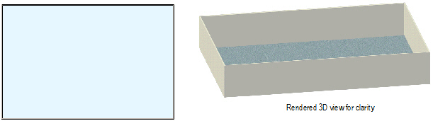
1 Create a closed 2D object (such as a rectangle, polyline, or polygon) to represent the room. The dimensions of the object should match the interior dimensions of the room to be created.
2 With the 2D object selected, select Event Design > Create Room.
The Create Room dialog box opens. Specify the properties and attributes of the walls and floor.
Click to show/hide the parameters.
3 Click OK. The room’s walls and floor are automatically created.
Wall and floor parameters can be edited in the Object Info palette; see “Editing Walls” on page 577 and “Creating Floors” on page 519.
~~~~~~~~~~~~~~~~~~~~~~~~~
 Creating the
Stage
Creating the
StageMany event rooms contain a stage for viewing presentations. Based on the Stage Plug tool, a stage is automatically created according to specified parameters.
The structure type of the stage plug is automatically set to Border.
To create the stage:
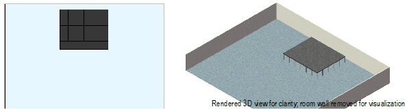
1 Create a closed 2D object (such as a rectangle, polyline, or polygon) to represent the stage. The dimensions of the object should match the dimensions of the stage to be created.
2 With the 2D object selected, select Event Design > Create Stage.
The Create Stage dialog box opens. Specify the stage properties and attributes.
Click to show/hide the parameters.
3 Click OK. The stage is automatically created.
Stage parameters can be edited in the Object Info palette; see “Inserting a Stage Plug” on page 999.
Right-click (Windows) or Ctrl-click (Mac) on the stage object and select Edit from the context menu. Edit the shape of the object path with the Reshape tool.
A stage can also be created by clicking the Stage Plug tool from the Spotlight tool set.
~~~~~~~~~~~~~~~~~~~~~~~~~
 Creating
Stage Stairs
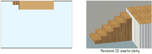
Creating
Stage StairsStairs or steps are usually required to provide access to the stage from the floor. The steps are automatically adjusted to meet the top of the stage. The stage stairs are based on the Stage Steps tool.
To add steps:
1 Select Event Design > Create Stair.
The Create Stair dialog box opens.
Click to show/hide the parameters.
2 Click OK.
3 Click once in the drawing to set the stair position. Click again to set the stair rotation.
Stair parameters can be edited in the Object Info palette; see “Inserting Stage Steps” on page 1002.
~~~~~~~~~~~~~~~~~~~~~~~~~
 Creating a
Lectern
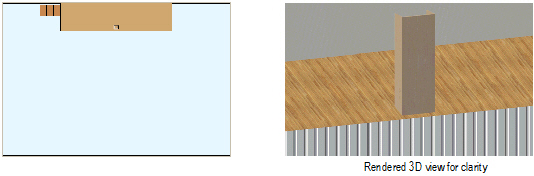
Creating a
LecternAfter the stage and stairs have been added, a lectern can be quickly configured and placed. When placed on the stage, the lectern elevation is automatically adjusted to the top of the stage.
To add a lectern:
1 Select Event Design > Create Lectern.
The Create Lectern dialog box opens.
Click to show/hide the parameters.
2 Click OK.
3 Click once in the drawing to set the lectern position. Click again to set the lectern rotation.
~~~~~~~~~~~~~~~~~~~~~~~~~
 Creating a
Video Screen
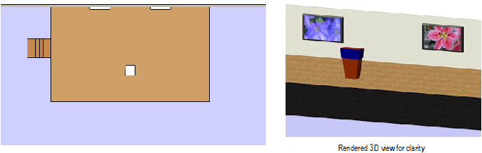
Creating a
Video ScreenAs part of the event design setup, video screens are often necessary at events and can be quickly configured and placed.
To add a video screen object:
1 Select Event Design > Create Screen.
The Create Screen dialog box opens.
2 Select the type of video screen object to insert, and click OK.
3 Click once in the drawing to set the video object position. Click again to set the object’s rotation.
Screen parameters can be edited in the Object Info palette; see “Inserting Video Screen Objects” on page 966.
~~~~~~~~~~~~~~~~~~~~~~~~~
 Creating Event
Seating
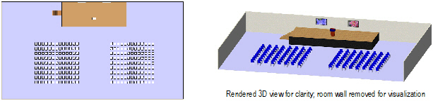
Creating Event
SeatingOnce the event room has been defined, one of the last steps is to add seating for the event. A variety of event seating types can be automatically created. Seating can consist of chairs, tables, or tables and chairs. Seating fills a 2D shape in a user-defined arrangement with a “look-to” location defined by a focal point. Along with the event seating, a Seating Count worksheet is created.
To add seating:
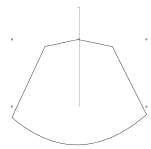
1 Create the closed 2D shape (such as a polygon, rectangle, rounded rectangle, oval, arc/circle, or polyline) defining the boundary of the seating area. Objects with one or more holes can be selected; seating will not be placed where a hole exists.
2 With the object selected, select Event Design > Create Event Seating.
The Create Event Seating dialog box opens.
Click to show/hide the parameters.
3 Click Customize Symbol to change the default appearance of the selected symbol if desired. This creates a new symbol that is added to the file’s resources.
The Customize Symbol dialog box opens.
Click to show/hide the parameters.
4 Click OK to return to the Create Event Seating dialog box.
5 Click OK to create the event seating. The Select the Focus Method dialog box opens.
6 Click Focus at Next Click to manually place the focal point for the seating, or click Automatically Focus to have the focal point created automatically.
If Focus at Next Click is selected, click once to place the focal point.
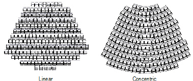
All seats will face this point; table and chair symbols orient toward the point. For concentric seat layouts, the distance of the seat focal point from the 2D boundary object determines the radius of the concentric layout. Click close to the object for a smaller radius.
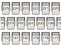
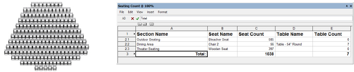
The event seating and a Seating Count worksheet are created, with automatically calculated seat and table counts. The Seating Count worksheet displays the number of seats and/or tables required for each seating section, as well as the total number of seats/tables needed for all sections. Nested symbols are counted in the worksheet, so tables and chairs are counted separately within a table and chair symbol. (If a symbol cannot be identified as a table or chair, it is counted as a chair.)
Seating parameters can be edited in the Object Info palette and have the same parameters as the Create Seating Layout command (see “Editing the Seating Layout” on page 990).
~~~~~~~~~~~~~~~~~~~~~~~~~
 Creating a
Seating Layout
Creating a
Seating LayoutThe Create Seating Layout command creates a seating layout object from one or more selected polygons, rectangles, rounded rectangles, ovals, arcs/circles, or polylines. Seating can consist of chairs, tables, or tables and chairs. Seating fills the objects in a user-defined arrangement with a “look-to” location defined by a control point. Seating layout objects can also be created by drawing a polyline and then selecting the Create Objects from Shapes command (see “Creating Objects from Shapes” on page 301). Along with the seating layout, a Seating Count worksheet is created.
A seating layout can also be created by clicking the Seating Layout tool from the Furn/Fixtures tool set. Draw a polygon with the tool and complete the parameters which are identical to those described in “Editing the Seating Layout” on page 990. Alternatively, Vectorworks Spotlight users can use the Create Event Seating command on the Event Design menu to create a seating layout (see “Creating Event Seating” on page 986).
To create a seating layout object:
1 Create the shape defining the boundary of the seating area. Objects with one or more holes can be selected; seating will not be placed where a hole exists. Multiple shapes can be selected at one time (to create several seating sections, for example).
2 With the object selected, select the Create Seating Layout command from the appropriate menu:
• Architect workspace: AEC > Create Seating Layout
• Spotlight workspace: Spotlight > Architectural > Create Seating Layout
The Create Seating Layout dialog box opens.
Click to show/hide the parameters.
3 A default symbol can be created to represent the seating; select Create a new seat symbol called and provide a symbol name. Alternatively, select an appropriate seating symbol from a library or the current file. In addition to seat symbols, table symbols and table and chair symbols can be used.
See “Accessing Existing Resources” on page 251 for information on importing symbols into the Resource Browser.
4 Click OK to close the Create Seating Layout dialog box.
5 When prompted, click the focal point for the seating. All seats will face this point; table and chair symbols orient towards the point.
For concentric seat layouts, the distance of the seat focal point from the object determines the radius of the concentric layout. Click close to the object for a smaller radius.
The seating layout object and a Seating Count worksheet are created, with automatically calculated seat and table counts.
The Seating Count worksheet displays the number of seats and/or tables required for each seating layout section, as well as the total number of seats/tables needed for all sections. Nested symbols are counted in the worksheet, so tables and chairs are counted separately within a table and chair symbol. (If a symbol cannot be identified as a table or chair, it is counted as a chair.)
~~~~~~~~~~~~~~~~~~~~~~~~~
 Editing
the Seating Layout
Editing
the Seating LayoutSeating layout parameters can be edited in the Object Info palette.
Click to show/hide the parameters.
The seating layout can be reshaped with the Reshape tool to add, subtract, and change vertices. The seats are automatically adjusted to fit the new shape. More sophisticated editing operations, such as adding, clipping, intersecting and combining into surfaces can be performed on the seating layout path object by selecting Modify > Edit Seating Layout.
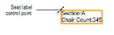
The seating section name and seating count text position can be adjusted by moving the control point. Adjust the text font and size of the label and seat numbers with the commands from the Text menu.
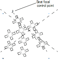
If the seating orientation requires adjustment, the seat control point can be moved to readjust the seating focal point. The control point is referenced relative to the center of the seating layout. If two imaginary axis lines were placed over the seating layout as shown in the diagram, placing the control point in line with the center of the axes would orient the seats directly toward the control point.
~~~~~~~~~~~~~~~~~~~~~~~~~
 Seating
Layout Specifications
Seating
Layout SpecificationsThe Create Seating Layout command in the Vectorworks Architect and Spotlight products, as well as the event design suite in the Vectorworks Spotlight product, make use of table and chair symbols that are available from the default content. It’s also possible to make your own table, chair, and nested table and chair symbols for use with these features.
Symbols should be hybrid (2D/3D) so that they display properly in both 2D and 3D views. At a minimum, the symbol must contain a 2D representation.
Create the 2D view of the symbol using as few polygons and lines as possible. If possible, use a single polyline rather than individual line segments. The line weight of the symbol is also a consideration; the symbols need to stand out when printed. The outer perimeter of the symbol should have a line weight of at least 1/2 point (7 mils). Interior details should use a lighter line weight. The 2D representation should have a solid fill so that it obscures information under the symbol.
Keep the 3D symbol simple. It should be solid. The model should be accurately sized, but without minute details. These items can add significantly to the rendering time required, and are not necessary to distinguish among objects.
To create a table and chair symbol, create the chair and table symbols separately, and then create a symbol from the table and chair symbols, so that the table and chair symbols are nested symbols.
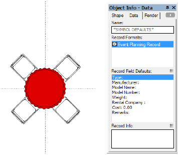
Attach the Event Planning Record to the symbol, with the Type field indicating whether the symbol is a table or chair. This allows the Seating Count worksheet to accurately count tables and chairs.
To attach the event planning record:
1 In the Resource Browser, import the Event Planning Record from the Seating.vwx default event planning library file.
Locate the Event Planning Record and select Import from the Resources menu to bring the record into the current file.
2 Select the new seating symbol, and select Modify > Edit Symbol.
If attaching the record to nested table and chair symbols, select the table or chair, and select Modify > Edit Symbol again to edit the individual table or chair. After attaching the event planning record to one of the nested symbols, repeat the procedure to attach the record to the other symbol.
3 In the Edit Symbol window, click a blank area so that nothing is selected.
4 Click the Data tab in the Object Info palette. Attach the Event Planning Record to the symbol defaults by selecting the check box. Then edit the record by selecting the record field and entering its record information. The Type field for tables should contain “Table“ for tables and “Chair” for chairs, for proper object identification and inclusion in worksheets.
5 Click Exit Symbol at the upper right corner of the window to return to the drawing.
~~~~~~~~~~~~~~~~~~~~~~~~~
 Creating
Event Views
Creating
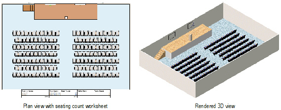
Event ViewsOnce the desired elements of the event have been added to the room, it is often necessary to create views of the room to show to the client. The Create Views command automatically creates two sheet layers of the event layout: a 2D plan view and a rendered isometric view. The Plan View sheet layer displays the layout in a Top/Plan, Wireframe mode viewport, and includes the seating count worksheet. The Rendered View sheet layer displays the layout in an isometric viewport, rendered in OpenGL mode.
To create a 2D and 3D rendered view of the event layout:
1 Select Event Design > Create Views.
2 The views are automatically created. The rendered viewport may require updating; with the viewport selected, click Update from the Object Info palette.
~~~~~~~~~~~~~~~~~~~~~~~~~