Several commonly used structural steel shapes are available as 2D objects. 3D equivalents of these objects are also available in the Vectorworks Design Series products. Since the 2D and 3D parameters are nearly identical, all parameters are documented with the 2D objects for convenience. Two additional 2D/3D structural shapes are also available in the Vectorworks Design Series products: bulb flat and Z-section, as well as four additional series (ANZ, BSI, DIN, and JIS).
The Update Plug-in Objects command may need to be run on files containing structural shapes that were created in an earlier version of Vectorworks software. This command converts the structural shapes to the latest format; see “Migrating from Previous Versions” on page 34.
~~~~~~~~~~~~~~~~~~~~~~~~~

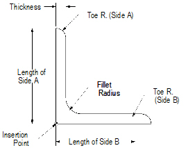
1 Click the Angle tool from the Detailing tool set.
2 Click to place the object in the drawing, and click again to set the rotation.
The first time you use the tool in a file, a properties dialog box opens. Set the default properties, and click OK. The properties can be edited from the Object Info palette.
Click to show/hide the parameters.
~~~~~~~~~~~~~~~~~~~~~~~~~
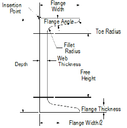

1 Click the Channel tool from the Detailing tool set.
2 Click to place the object in the drawing, and click again to set the rotation.
The first time you use the tool in a file, a properties dialog box opens. Set the default properties, and click OK. The properties can be edited from the Object Info palette.
Click to show/hide the parameters.
~~~~~~~~~~~~~~~~~~~~~~~~~
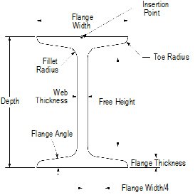

1 Click the I-Beam tool from the Detailing tool set.
2 Click to place the object in the drawing, and click again to set the rotation.
The first time you use the tool in a file, a properties dialog box opens. Set the default properties, and click OK. The properties can be edited from the Object Info palette.
Click to show/hide the parameters.
~~~~~~~~~~~~~~~~~~~~~~~~~
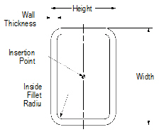

To create rectangular tubing:
1 Click the Rectangular Tubing tool from the Detailing tool set.
2 Click to place the object in the drawing, and click again to set the rotation.
The first time you use the tool in a file, a properties dialog box opens. Set the default properties, and click OK. The properties can be edited from the Object Info palette.
Click to show/hide the parameters.
~~~~~~~~~~~~~~~~~~~~~~~~~
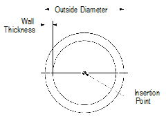

To create round tubing:
1 Click the Round Tubing tool from the Detailing tool set.
2 Click to place the object in the drawing, and click again to set the rotation.
The first time you use the tool in a file, a properties dialog box opens. Set the default properties, and click OK. The properties can be edited from the Object Info palette.
Click to show/hide the parameters.
~~~~~~~~~~~~~~~~~~~~~~~~~
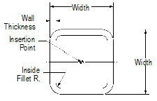

To create square tubing:
1 Click the Square Tubing tool from the Detailing tool set.
2 Click to place the object in the drawing, and click again to set the rotation.
The first time you use the tool in a file, a properties dialog box opens. Set the default properties, and click OK. The properties can be edited from the Object Info palette.
Click to show/hide the parameters.
~~~~~~~~~~~~~~~~~~~~~~~~~
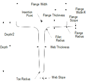

1 Click the Tee tool from the Detailing tool set.
2 Click to place the object in the drawing, and click again to set the rotation.
The first time you use the tool in a file, a properties dialog box opens. Set the default properties, and click OK. The properties can be edited from the Object Info palette.
Click to show/hide the parameters.
~~~~~~~~~~~~~~~~~~~~~~~~~
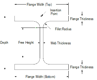

To create a wide flange:
1 Click the Wide Flange tool from the Detailing tool set.
2 Click to place the object in the drawing, and click again to set the rotation.
The first time you use the tool in a file, a properties dialog box opens. Set the default properties, and click OK. The properties can be edited from the Object Info palette.
Click to show/hide the parameters.
~~~~~~~~~~~~~~~~~~~~~~~~~

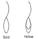
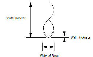
To insert a shaft break:
1 Click the Shaft Break tool from the Detailing tool set.
2 Click to define the start point, click again to define the end point and rotation, and drag the cursor and click to set the width.
The first time you use the tool in a file, a properties dialog box opens. Set the default properties, and click OK. The properties can be edited from the Object Info palette.
Click to show/hide the parameters.
~~~~~~~~~~~~~~~~~~~~~~~~~
 Shaft
Break 2
Shaft
Break 2
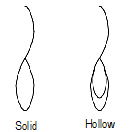
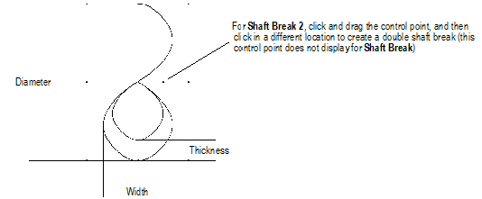
To insert a shaft break 2 object.
1 Click the Shaft Break 2 tool from the Detailing tool set.
2 Click to define the start point, click again to define the end point and rotation, and drag the cursor and click to set the width.
The first time you use the tool in a file, a properties dialog box opens. Set the default properties, and click OK. The properties can be edited from the Object Info palette.
Click to show/hide the parameters.
~~~~~~~~~~~~~~~~~~~~~~~~~

1 Click the Slot tool from the Detailing tool set.
2 Click to define the start point of the slot, click again to define the end point and rotation, and drag the cursor and click to set the slot width.
Click to show/hide the parameters.
~~~~~~~~~~~~~~~~~~~~~~~~~
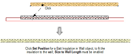
The Batt Insulation tool draws a planar insulation fill along a line. This tool is useful for creating custom details. The insulation can be placed within a wall, where it automatically adjusts to the length of the wall.
A better method of creating insulation fills, especially for walls, is to use a tile fill, which scales and rotates within walls and slab and wall components.

To create batt insulation:
1 Click the Batt Insulation tool from the Detailing tool set.
2 Click to place the object in the drawing, and click again to set the length and rotation.
The first time you use the tool in a file, a properties dialog box opens. Set the default properties, and click OK. The properties can be edited from the Object Info palette.
3 The created batt insulation can be dragged into an existing wall.
Click to show/hide the parameters.
~~~~~~~~~~~~~~~~~~~~~~~~~
 Bulb Flat
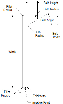

To create a bulb flat object:
1 Click the Bulb Flat tool from the Detailing tool set.
2 Click to place the object in the drawing, and click again to set the rotation.
The first time you use the tool in a file, a properties dialog box opens. Set the default properties, and click OK. The properties can be edited from the Object Info palette.
Click to show/hide the parameters.
~~~~~~~~~~~~~~~~~~~~~~~~~
 Z-Section
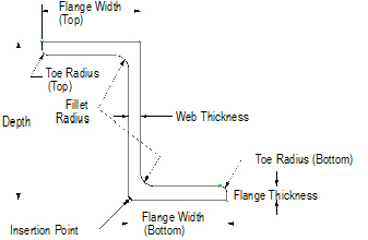

1 Click the Z-Section tool from the Detailing tool set.
2 Click to place the object in the drawing, and click again to set the rotation.
The first time you use the tool in a file, a properties dialog box opens. Set the default properties, and click OK. The properties can be edited from the Object Info palette.
Click to show/hide the parameters.
~~~~~~~~~~~~~~~~~~~~~~~~~
 Framing
The Vectorworks Architect software includes a suite of tools for developing framing plans. There are tools for framing roofs, walls, and floors. Both architects and builders can take advantage of these tools to visualize framing details while still in the design stage of a project, to generate framing detail drawings, and to develop material take-off lists. The Simple Beam Calculator command is also available for analysis of a simply-supported beam with a single load.
A roof face area worksheet can also be added to the drawing from the VA Create Schedule command or the Resource Browser. From the Resource Browser, select Vectorworks Libraries from the Files list, and open the default architectural reports file that is included with the Vectorworks Architect product (see “Resource Libraries” on page 239). Drag the Roof Face Area worksheet to the drawing. The worksheet is populated with information from the objects in the current drawing.
~~~~~~~~~~~~~~~~~~~~~~~~~
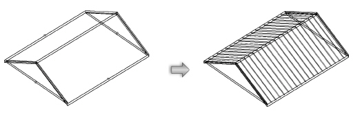
 Framing a
Roof
Framing a
RoofA roof object can be automatically framed with rafters, collars (collar beams), ridges, and other roof elements with the Roof Framer command. The command creates framing member objects. If Enable Auto-classing is selected in the Standard Naming dialog box, all roof framing members will be automatically placed in the Structural-Framing class.
This command does not work on roof face objects.
To automatically frame a roof:
1 Select the roof object.
2 Select AEC > Framing > Roof Framer.
The Roof Framer dialog box opens.
3 Select the tab for the type of roof framing element to create, and select the check box to create the framing element. More than one type can be selected at the same time; other framing elements can be added later.
An individual framing element can be added with the Framing Member tool, available from the Detailing tool set.
4 Enter the framing parameters for each desired framing element as described in the following sections.
5 For each selected roof framing element, click Object Attributes to specify its appearance.
The Attributes dialog box opens. See “Applying Object Attributes” on page 1147 for information on applying graphic attributes, and “Applying and Mapping Textures” on page 1607 for information on texture parameters.
Click to show/hide the parameters.
6 Click OK to return to the Roof Framer dialog box.
7 Click OK to frame the roof.
~~~~~~~~~~~~~~~~~~~~~~~~~
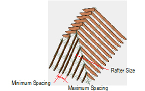
 Creating
Rafters
Creating
RaftersTo create rafters:
1 In the Roof Framer dialog box, click the Rafters tab, and select Create Rafters.
2 Specify the rafter parameters.
Click to show/hide the parameters.
3 Click OK to create the rafters.
~~~~~~~~~~~~~~~~~~~~~~~~~
 Creating
Collars
Creating
CollarsTo create collars (collar beams):
1 In the Roof Framer dialog box, click the Collars tab, and select Create Collars.
2 Specify the collar parameters.
Click to show/hide the parameters.
3 Click OK to create the collars.
~~~~~~~~~~~~~~~~~~~~~~~~~
 Creating
Plates
Creating
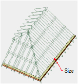
PlatesTo create plates:
1 In the Roof Framer dialog box, click the Plates tab, and select Create Plates.
2 Specify the plate parameters.
Click to show/hide the parameters.
3 Click OK to create the plates.
~~~~~~~~~~~~~~~~~~~~~~~~~
 Creating
Purlins
Creating
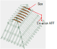
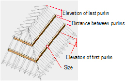
PurlinsTo create purlins:
1 In the Roof Framer dialog box, click the Purlins tab, and select Create Purlins.
2 Specify the purlin parameters.
Click to show/hide the parameters.
3 Click OK to create the purlins.
~~~~~~~~~~~~~~~~~~~~~~~~~
 Creating
Ridges
Creating
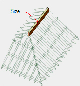
RidgesTo create ridges:
1 In the Roof Framer dialog box, click the Ridges tab, and select Create Ridges.
2 Specify the ridge parameters.
Click to show/hide the parameters.
3 Click OK to create the ridges.
~~~~~~~~~~~~~~~~~~~~~~~~~
 Creating
Trimmers
Creating
TrimmersTo create trimmers:
1 In the Roof Framer dialog box, click the Trimmers tab, and select Create Trimmers.
2 Specify the trimmer parameters.
Click to show/hide the parameters.
3 Click OK to create the trimmers.
~~~~~~~~~~~~~~~~~~~~~~~~~
 Creating
Hip and Valley Rafters
Creating
Hip and Valley RaftersTo create hip and valley rafters:
1 In the Roof Framer dialog box, click the Hips/Valleys tab, and select Create Hips and Valleys.
2 Specify the hip and valley rafter parameters.
Click to show/hide the parameters.
3 Click OK to create the hip and valley rafters.
~~~~~~~~~~~~~~~~~~~~~~~~~
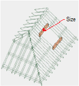
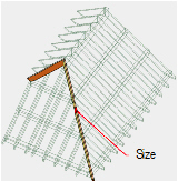
 Custom
Frame Element Sizes
Custom
Frame Element SizesThe size of the framing elements can be selected from a pre-set list, or the list can be edited to contain desired or custom sizes.
To edit the size list of the frame elements:
1 From the Size field in one of the framing element tabs of the Roof Framer dialog box, select Edit List.
The Edit Size List dialog box opens, listing the currently available sizes of the roof element.
Click to show/hide the parameters.
2 Click OK to edit the size list.
The text files that populate the size lists in the framing element dialog boxes can also be edited. The text files are located in the Vectorworks application folder [Vectorworks]\Plug-Ins\VW_Arch\Data.
~~~~~~~~~~~~~~~~~~~~~~~~~
 Creating Framing
Members
Creating Framing
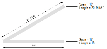
MembersThe Framing Member tool draws framing elements for rafters, beams, joists, and framing members with a horizontal projection.
For a file created in a version of Vectorworks software prior to 2009, board, joist, rafter, and original framing member objects are considered to be “legacy” objects. To convert them to the current functionality of the framing member tool, select Tools > Utilities > Update Plug-in Objects; see “Migrating from Previous Versions” on page 34.

To create a framing member:
1 Select the Framing Member tool from the Detailing tool set.
2 Click to place the object in the drawing, and click again to set the length and rotation.
The first time you use the tool in a file, a properties dialog box opens. Set the default properties, and click OK. The properties can be edited from the Object Info palette.
The starting point and direction in which the framing member is drawn determine which end is which. When a single framing member object is selected in Top/Plan view, a blue arrow is placed at the starting point and indicates the object’s direction.

Click to show/hide the parameters.
~~~~~~~~~~~~~~~~~~~~~~~~~
 Framing a Floor
Use the Create Joists from Poly command to create the joist and perimeter objects necessary to frame a floor. If the floor is a slab object, select the slab component to serve as a boundary for the joist area. The command creates framing member objects.
To frame a floor:
1 Select a slab, polygon, polyline, or floor object.
If a stairwell hole exists in the floor, solid beam framing member objects are used for the headers.
2 Select AEC > Framing > Create Joists from Poly.
The Create Joist from Poly dialog box opens.
Click to show/hide the parameters.
3 Select whether to draw joists and/or perimeter framing members for the floor framing. Then, specify the properties of the joists and the perimeter framing. Click Set Joist Properties or click Set Framing Member Properties.
The Set Joist Properties or Set Framing Member Properties dialog box opens. The available parameters depend on the Type of joist or framing member selected.
Click to show/hide the parameters.
4 Click OK to set the joist or perimeter framing member properties.
5 Specify the attributes of the joists and the perimeter framing. Click Set Joist Attributes or click Set Framing Member Attributes.
The Set Joist Attributes or Set Framing Member Attributes dialog box opens. The dialog boxes are identical whether setting joist or perimeter framing attributes, and contain a Graphic Attributes tab and Texture tab (Renderworks required).
Click to show/hide the parameters.
6 Click OK to set the joist or perimeter framing member attributes.
7 Click OK to close the Create Joist From Poly dialog box.
8 If joists are to be created, an alert dialog box requests the selection of two points to set the joist orientation. Click OK to close the dialog box and click two points to indicate the desired joist orientation.
9 The joists and/or perimeter framing member objects are created. In addition, a Joist Take-Off worksheet is automatically created and added to the Resource Browser.
The framing member parameters can be edited from the Object Info palette. These parameters are identical to those of a single framing member object.
~~~~~~~~~~~~~~~~~~~~~~~~~
 Framing a Wall
The Vectorworks Architect product creates a highly detailed estimate of the placement and number of studs needed to frame walls. In addition to showing stud placement in a framing diagram, the Wall Framer command also automatically generates frame elevation drawings and two different worksheets, Frame TakeOff and Frame Wall Info.
To use the wall framer:
1 Ensure that the walls have the desired height. If necessary, change the wall height.
2 Select AEC > Framing > Wall Framer.
If a framing model has not yet been created, the New Framing Model dialog box opens. Enter a name for the framing model design layer (up to eight characters).
3 Click Create.
The Wall Framing dialog box opens. Select the desired settings for the framing model.
Click to show/hide the parameters.
The framing diagram and the 3D model representations also include symbols and inserted items, such as doors and windows.
The Wall Class dialog box opens. Enter the framing parameters for each wall class.
Click to show/hide the parameters.
5 Click OK to return to the Wall Framing dialog box.
6 Click OK to create the framing model.
The program creates the estimated framing for the walls and any other output information requested.
The 2D results display in Top/Plan view without a top plate. To view the results with a top plate, switch to another view such as Front, Back, Left, or Right.
To view the 3D results, switch to a view such as Left Isometric or Right Isometric.
The Framer TakeOff and Framer Wall Info worksheets, if created, display in the drawing area.
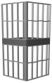
 Inserting
Ceiling Grid Objects
Inserting
Ceiling Grid Objects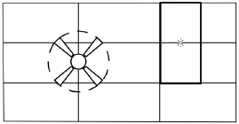
Use the Ceiling Grid tool to insert a ceiling grid object containing tiles with user-specified length, width, and placement angle. A ceiling grid object can also be created by drawing a polyline and then selecting the Create Objects from Shapes command (see “Creating Objects from Shapes” on page 301).

To insert a ceiling grid object:
1 Click the Ceiling Grid tool from the Furn/Fixtures tool set or the MEP tool set.
2 Click in the drawing file to set the start point of the ceiling grid object, and then click to set the position of each additional vertex. Click the last point to complete creation of the ceiling grid object. If the polyline is open, the program automatically completes it.
The first time you use the tool in a file, a properties dialog box opens. Set the default properties, and click OK. The properties can be edited from the Object Info palette.
3 Use the Reshape tool to modify the locations of the vertices after object creation, or use the vertex editing controls from the Object Info palette to move the vertices or change the degree of vertices. The tiles are automatically adjusted to fit the new shape.
Click to show/hide the parameters.
For information on editing object vertices, see “Reshaping Objects” on page 1095.